Lubnar Alkhteeb*![]() | M.B. Dawood
| M.B. Dawood![]()
© 2025 The authors. This article is published by IIETA and is licensed under the CC BY 4.0 license (http://creativecommons.org/licenses/by/4.0/).
OPEN ACCESS
This paper investigates the Structural behavior of recycled aggregate concrete continuous beam with hybrid reinforcement under monotonic and repeated loads. The experimental work includes testing 15 continuous beams, two specimens without recycled aggregate, and other beams cast with recycled aggregate. One specimen with recycled aggregate containing steel fiber was treated as a reference for specimens reinforced with FRP. Three specimens were cast with 20%, 40%, and 70% replacement ratios of recycled aggregate. GFRP, CFRP, and BFRP reinforced the other three specimens, containing 40% recycled aggregate and 1% steel fiber volume fraction. Three specimens were reinforced with hybrid reinforcement (steel and FRP bar), including 40% recycled aggregate and steel fiber. The last three beams were reinforced with hybrid reinforcement and tested under repeated load. The specimens' dimensions are 225mm in depth, 150mm in width, and 3000mm in length, consisting of two equal spans of 1400mm for each span. The test variables are the replacement ratio of recycled aggregate, changing the reinforcement type, loading form, and adding steel fiber. The test results showed that using recycled aggregate led to a slight decrease in ultimate load up to 5.38%. Using steel fiber led to an increase in the ultimate load by up to 10%. All specimens with recycled aggregate and reinforced with FRP bars showed a decrease in ultimate load by up to 47%. Using hybrid reinforcement led to an increase in ultimate load up to 53.8%. The specimens tested under repeated load showed a decrease in ultimate load by up to 15%.
continuous beam, FRP bars, recycled aggregate, repeated load, hybrid reinforcement, steel fiber
The most common material used in construction is concrete. There has been a significant global demand for concrete in recent decades due to the rapid rise of industrialization and urbanization. In a concrete mix, coarse and fine natural aggregates comprise around 70% of the total volume. Current estimates indicate that about 20 billion tons of construction aggregates are needed annually worldwide [1].
Old structures are frequently demolished, and new ones are built due to a change in purpose, structural decay, city rearrangement, traffic direction expansion, and natural disasters. The European Union generates around 850 million tons of construction and demolition garbage annually, accounting for 31% of total waste creation [2]. In China, construction and demolition waste accounts for 30%–40% of the total city solid waste [3].
It is estimated that 123 million tons of construction waste are generated annually in the USA only from demolition [4]. Over 3 million tons of waste rubble—largely concrete—are generated annually in Australia. The remaining material is disposed of in landfills, and approximately half is recycled into an RCA. Today, many countries, including Japan, Germany, and the Netherlands, have established standards and guidelines for using recycled aggregates in structural and non-structural applications, with typical replacement ratios ranging from 30% to 100%, depending on the application and performance requirements [5]. As long as high-quality products are produced, using (RA) recycled aggregates is a good way to address the issue of growing throwaway material [6]. It is essential to consider the usage of recycled aggregate (RA) in concrete as a trend to protect the environment and support the economy. Since the end of World War II, concrete pavement has been demolished, and recycled aggregate has been used in construction to stabilize the base course for new roads. Using recycled aggregate in the building sector has several benefits, including being cost-effective and environmentally friendly [7]. When RCA is used in construction, less NCA is required, which lessens the adverse environmental effects of extracting virgin aggregates. The lack of NCA and rising landfill fees also encourage using RCA in concrete. Additionally, the contractors are forced to consider replacing NCA with RCA due to the greater distance between the construction sites and the sources of high-quality natural aggregates [2].
Fiber Reinforced Polymers (FRP) were used in engineering for structural elements when concrete was made using polymer materials rather than steel bars [8]. In addition to their high strength-to-weight ratio, fiber-reinforced polymer (FRP) bars are non-corrosive, making them a significant substitute for standard steel bars that increase the durability of concrete structures [9]. FRP-reinforced concrete (RC) constructions exhibit brittleness, high deflections, and wide cracks due to their linear elastic behavior up to failure and the low elastic modulus of FRP bars under tensile stress. Furthermore, because the majority of concrete structures are continuous elements, the utilization of FRP reinforcement influenced the ability of these structures to redistribute moments between mid-support and midspan compared to under-reinforced steel structures, leading to unexpected failure without adequate warning. Consequently, several techniques have been suggested to increase the ductility of FRP-RC beams [10]. FRP and steel reinforcement have been proposed as a workable and efficient way to solve issues with concrete constructions. The steel bars are more effective regarding rigidity and ductility, but the steel bars within the cross-section make less contribution to the element's strength. Additionally, the width and spacing of cracks are decreased when steel reinforcement is present. Consequently, compared to FRP-RC beams, a combination of steel and FRP reinforcement offers better serviceability and ductility. To overcome the drawbacks of traditional steel reinforcement, such as its excessive weight and susceptibility to corrosion, the concept of hybrid reinforcement first surfaced in the latter half of the 20th century. Steel's ductility and energy-absorbing ability are preserved in hybrid systems, which take advantage of non-metallic materials' high tensile strength and resistance to corrosion. According to recent research, hybrid reinforcement can improve concrete structures' resilience to cracks, longevity, and seismic performance, especially in harsh, chloride-rich, or maritime conditions. Bridge decks, precast elements, and retrofitted structures are currently used to combine various reinforcing types to enhance long-term performance. However, cost-effectiveness, interfacial bonding, and material compatibility still require investigation [11].
Various studies have investigated the behavior of beams with hybrid reinforcement and those with recycled aggregate from the past to present. In 2000, Lin and Chien [12] stated the influence of the ductility of the section on the redistribution of the moment of the reinforced concrete beam. The results show that growth in compression reinforcement and decreased tensile reinforcement will lead to more moment redistribution and raise ductility. In 2008, Ashour and Habeeb [13] studied the performance of continuous beams reinforced with CFRP bars. The experimental test outcomes showed that raising the ratio of CFRP reinforcement in the bottom layer of continuous and simply supported specimens is the main factor in controlling deflection and improving the strength of the beam. In 2009, Kou and Poon [14] investigated the hardened and fresh characteristics of SCC by utilizing recycled aggregate as both fine and coarse. Three mixtures were used in the experimental work. The findings show that the SCC properties produced from crushed fine recycled aggregates and river sand showed only a slight difference. In 2011, Yoon et al. [15] introduced an experimental study to evaluate the deflection and flexural capacity of HSC beams reinforced with numerous layers of various reinforcement kinds (GFRP, steel, and CFRP). The results showed that the hybrid reinforcement with steel bars enhanced and controlled the stiffness, low post-cracking, deep crack propagation, high deflection, low ductility, and large crack width of beams reinforced with FRP bars. In 2013, Hameed [16] studied the effect of using steel fiber and the RCA made by destroying concrete as a coarse aggregate on the mechanical properties of concrete. The test results show that the tensile strength and compressive strength will decrease by increasing the percentage ratio of recycled aggregate increases. However, the mixture with steel fiber increased tensile and compressive strength. In 2018, Seara-Paz et al. [17] investigated the flexural behavior of beams with recycled aggregate exposed to the load until failure. The test results show that conventional concrete's yielding, service, and ultimate state generally behaved like that of recycled concrete. However, the cracking behavior exhibits differences between the traditional and recycled aggregate. In 2020, Lu et al. [18] investigated the serviceability performance and flexural behavior of hybrid Glass-Basalt bars reinforced concrete beams and steel bars. The outcomes exhibited that the beams' bending moment capacity with hybrid reinforcement was about 91-97% compared with beams with steel reinforcement only, with identical reinforcement ratio. However, their maximum crack width and deflection were 20%-60 % larger than those of beams reinforced with steel bars under similar load levels. In 2020, Almahmood et al. [10] presented a study about the structural response of full-scale reinforced concrete continuous T beams with hybrid reinforcement. The findings exhibited that using steel bars with glass fiber to reinforce concrete T-beams enhances ductility, flexural stiffness, and deflection and crack width control serviceability. In 2020, Hassan and Faroun [19] examined the response of hybrid deep beams. The specimens were subjected to repeated and monotonic loading under two-point loads. The experimental results showed that the carrying capacity of the beam decreased when the beam was exposed to repeated loading of various levels. In 2021, Diab et al. [20] presented numerical and experimental studies to comprehend the failure and behavior of hybrid reinforced concrete T-beams in flexural by steel bars and CFRP bars at hogging and sagging zones. The test outcomes observed that utilizing the hybrid bars at both sagging and hogging regions led to control of the serviceability limits of the beams and the kind of reinforcement bar's effects on the mode of failure and moment redistribution ratio.
From a previous study, it can be observed that there is limited research on the behavior of a continuous beam with recycled aggregate and limited research on the performance of the constant beam with hybrid reinforcement containing recycled aggregate. So, this study examines how continuous beams of recycled aggregate concrete with hybrid reinforcement behave structurally under repeated and monotonic stresses. The goal of this study is to add to the body of knowledge required for creating concrete structures that are more resilient, long-lasting, and environmentally friendly by combining these two cutting-edge techniques: enhanced reinforcement strategies (hybrid reinforcement) and sustainable material use (recycled aggregate). Fifteen continuous beams will be tested as part of the experimental project to methodically assess the effects of loading conditions (monotonic and repeated), reinforcement types (GFRP, CFRP, BFRP, steel, and hybrid), and recycled aggregate replacement ratios on the structural performance.
The experimental test includes the following samples:
1- 18 cylinders with dimensions 100 mm × 200 mm (three for each mixture) to measure tensile strength.
2- 18 cubes with dimensions 150 mm × 150 mm × 150 mm (three for each mixture) to measure compressive strength.
3- 15 continuous beam (two of NCA and 13 specimens with RCA and NCA).
2.1 Test continuous beams
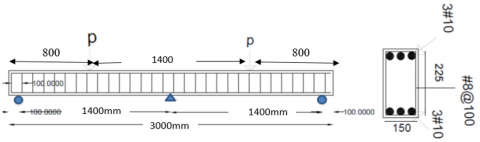
The work includes casting 15 continuous beams. The dimension of the specimens is 3000 mm in length, consisting of two equal spans of 1400mm for each span, 225mm in depth, and 150mm in width. A Ɵ10mm steel bar was used to reinforce the control specimen at the top and bottom. Ɵ8 at 100mmc/c was used to reinforce the shear zone. The details of the control beam are shown in Figure 1. The test variables are the replacement ratio of recycled aggregate, changing the reinforcement type, loading type, and adding steel fiber.
Figure 1. Dimension and reinforcement of the control continuous beam
The details of the specimens are shown in Table 1. The beams BR0F1 and BR0F2 are cast from standard concrete, while other specimens are cast with recycled aggregate. Group 1 includes specimens with different percentage ratios of RCA. The first specimen consists of a 20% replacement ratio of RCA, while the second specimen contains a 40% replacement ratio of RCA. The third specimen casting has a 70% replacement ratio. One specimen casting with a 40% replacement ratio and containing 1% steel fiber was treated as a reference beam for the specimen reinforced with FRP bar only. Group two includes two specimens. The first specimen was reinforced with 3Ɵ10 GFRP at the top and bottom.
Table 1. The details of specimens
|
Sample |
Percent Ratio of RCA |
Top Reinforcement |
Bottom Reinforcement |
Type of Loading |
Note |
|
CBR0F1 |
0% |
3Ɵ10 steel |
3Ɵ10 steel |
Monotonic load |
Control beam |
|
CBR0F2 |
0% |
3Ɵ10 steel |
3Ɵ10 steel |
Repeated load |
|
|
BR20F1 |
20% |
3Ɵ10 steel |
3Ɵ10 steel |
Monotonic load |
Change the percentage ratio of RCA |
|
BR40F1 |
40% |
3Ɵ10 steel |
3Ɵ10 steel |
||
|
BR70F1 |
70% |
3Ɵ10 steel |
3Ɵ10 steel |
||
|
BR40VF1 |
40% |
3Ɵ10 steel |
3Ɵ10 steel |
Monotonic load |
Add steel fiber |
|
BGR40VF1 |
40% |
3Ɵ10 GFRP |
3Ɵ10 GFRP |
Monotonic load |
Change the type of reinforcement and ratio |
|
BCR40VF1 |
40% |
3Ɵ10 CFRP |
3Ɵ10 CFRP |
||
|
BBfR40VF1 |
40% |
3Ɵ10 BFRP |
3Ɵ10 BFRP |
||
|
BHR40VF (G-S) |
40% |
2Ɵ10 steel and 1Ɵ10 GFRPSS |
2Ɵ10 steel and 1Ɵ10 GFRP |
||
|
BHR40VF1 (C-S) |
40% |
2Ɵ10 steel and 1Ɵ10 CFRP |
2Ɵ10 steel and 1Ɵ10 CFRP |
||
|
BHR40VF1(Bf-S) |
40% |
2Ɵ10 steel and 1Ɵ10 BFRP |
2Ɵ10 steel and 1Ɵ10 BFRP |
||
|
BHR40VF2(G-S) |
40% |
2Ɵ10 steel and 1Ɵ10 GFRP |
2Ɵ10 steel and 1Ɵ10 GFRP |
Repeated load (0.7Pu) |
The influence of repeated load with various types of reinforcement |
|
BHR40VF2 (C-S) |
40% |
2Ɵ10 steel and 1Ɵ10 CFRP |
2Ɵ10 steel and 1Ɵ10 CFRP |
||
|
BHR40VF2(Bf-S) |
40% |
2Ɵ10 steel and 1Ɵ10 BFRP |
2Ɵ10 steel and 1Ɵ10 BFRP |
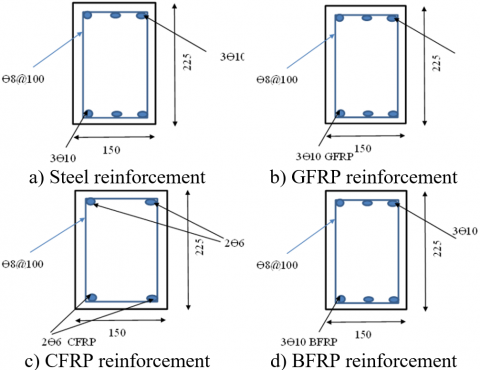
The second specimen was reinforced with hybrid reinforcement in which 2Ɵ10 steel + 1Ɵ10GFRP was used at the top and bottom of the specimens. Group three and group four were similar to group two, with one difference: in group three, the CFRP was used to reinforce the specimens, while in group four, the BFRP was used to reinforce the specimens. In group five, the type of loading was changed from monotonic to repeated load. BROF2, BHR40VF2(C-S), BHR40VF2(bf-S), and BHR40VF2(G-S) were tested under repeated load (10 cycles, gradually loading and unloading up to 70% of carrying capacity for the same specimen under monotonic loading). After 10 cycles, the specimen was loaded until failure. The details of the specimens are shown in Figure 2.
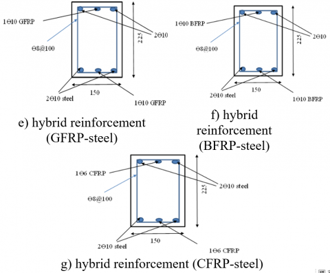
Figure 2. Type of reinforcement of the beam
2.2 Materials properties
1- The cement is ordinary Portland cement (salt resistance cement) named Tasluja cement.
2- Natural sand taken from the sea of Najafi is used as fine aggregate.
3- Tab water was used for all mixtures.
4- Natural gravel, crushed gravel with a maximum size of 19mm, was used as coarse aggregate.
5- Recycled aggregate used in this study was prepared by destroying the cube from old normal concrete, with a maximum size of recycled aggregate of 19mm.
6- Sika Viscocrete-905S was used as a high-water-reducing mixture in all the mixtures.
7- Hooked steel fiber with a length of 35mm and a diameter of 0.5mm was used in this study
8- Deformed steel bars were used with a diameter of Ɵ10 for reinforced mid-span and mid-support regions. Ɵ8 was used for strips to reinforce the shear region. A tensile test for all specimens was done in the quality control laboratory, and the test results confirmed ASTM A615-16 [21]. Properties of steel reinforcement are listed in Table 2. The mix proportion used for NC and RCA is listed in Table 3. The results of tensile strength and compressive strength at 28 days are listed in Table 4.
Table 2. Test results of steel
|
Bar Diameter mm |
Actual Bar Diameter mm |
Ultimate Tensile Strength |
Yield Strength |
Elongation mm |
|
8 |
7.9 |
646 |
500 |
21% |
|
10 |
9.9 |
676 |
589 |
11.5 |
Table 3. Trail mix of NC and RCA
|
Mix |
R% |
Cement kg/m3 |
Fine Aggregate kg/m3 |
Coarse Aggregate kg/m3 |
Water kg/m3 |
Recycled Aggregate kg/m3 |
Steel Fiber kg/m3 |
Admixture (L/m3) |
|
1 |
0 |
400 |
704 |
1056 |
180 |
0 |
0 |
1 |
|
2 |
20 |
400 |
704 |
845 |
180 |
211.2 |
0 |
1 |
|
3 |
40 |
400 |
704 |
634 |
180 |
422.4 |
0 |
1 |
|
4 |
70 |
400 |
704 |
317 |
180 |
739 |
0 |
1 |
|
5 |
40 |
400 |
704 |
634 |
180 |
422.4 |
78 |
1 |
|
6 |
100 |
400 |
704 |
0 |
180 |
1056 |
0 |
1 |
Table 4. Tensile and compressive strengths
|
Specimen Name |
Compressive Strength |
Tensile Strength |
|
R0 |
34.124 |
2.891 |
|
R20 |
29.136 |
1.604 |
|
R40 |
26.168 |
1.427 |
|
R70 |
25.28 |
1.313 |
|
R100 |
24.72 |
1.22 |
|
R40V |
30.024 |
4.15 |
9- In this experimental work, three FRP bars (CFRP, GFRP, and BFRP) were used as the primary reinforcement. The diameters of the CFRP, GFRP, and BFRP were 6,10, and 10, respectively. The properties of FRP are listed in Table 5.
Their unique mechanical qualities, cost considerations, resilience to the environment, and application-specific needs are what influence the selection of Glass Fiber fiber-reinforced polymer (GFRP), Carbon Fiber Reinforced Polymer (CFRP), and Basalt Fiber Reinforced Polymer (BFRP) in structural applications. A comparison of their performance traits and a thorough justification for their selection are provided below:
Table 5. Properties of FRP bar
|
Type |
Bar Diameter |
Nominal Area (mm2) |
Tensile Strength at Ultimate Stage (MPa) |
Elasticity Modulus |
|
CFRP |
6 |
31.67 |
2241 |
124 |
|
GFRP |
10 |
71.26 |
827 |
46 |
|
BFRP |
10 |
71.2 |
900 |
45 |
1. Glass Fiber Reinforced Polymer (GFRP)
Justification for Use:
•Cost-Effectiveness: GFRP is the most cost-effective of the three, which makes it appropriate for projects with limited funds.
•Corrosion Resistance: GFRP is perfect for hostile situations (such as chemical plants and marine constructions) since it doesn't corrode like steel.
•Moderate Strength-to-Weight Ratio: This material offers enough reinforcement for various civil engineering applications, although not as strong as CFRP.
Electrical insulation might be helpful when conductivity is undesirable in electrical and telecommunications structures.
Performance Attributes:
•Elastic modulus: around 40-50 GPa (lower than steel, resulting in higher deformability); tensile strength: approximately 1,000-1,500 MPa
•Density: less than steel, about 1.8-2.1 g/cm³
•Thermal Expansion: Greater than steel, necessitating cautious design in fluctuating temperatures.
•Durability: If concrete isn't adequately covered, it is susceptible to alkaline degradation.
2. CFRP, or carbon fiber reinforced polymer
Justification for Use:
•High Strength & Stiffness: Among FRPs, CFRP has the highest tensile strength and modulus, which qualifies it for high-load applications like high-performance bridges, aerospace, and seismic retrofitting.
•Fatigue Resistance: Outstanding in situations involving dynamic loads.
•Lightweight: Allows for strengthening without requiring much extra mass.
•Precision Applications: Used in long-span structures and high-rise buildings where slight deflection is essential.
Performance Attributes:
•Depending on the fiber grade, the tensile strength ranges from 1,500 to 3,000 MPa.
•Elastic modulus: about 150–400 GPa (more than steel)
•Density: less than GFRP, at about 1.5 to 1.6 g/cm³
•Better at managing heat than GFRP/BFRP, this material has a higher thermal conductivity.
•Expense: Much more costly than GFRP/BFRP.
•Electrical Conductivity: This may cause problems for applications involving electromagnetic fields.
3. BFRP, or basalt fiber reinforced polymer
Justification for Use:
•Balanced Performance: Mechanical characteristics that fall somewhere between GFRP and CFRP.
•Natural & Sustainable Material: Basalt fibers are more environmentally friendly than synthetic alternatives because they are made from volcanic rock.
•Chemical and Temperature Resistance: Suitable for concrete reinforcement, it has superior alkali resistance to GFRP.
•Cost: A little more expensive than GFRP but less expensive than CFRP.
Performance Attributes:
•Elastic modulus: around 70–90 GPa (higher than GFRP, lower than CFRP); tensile strength: approximately 1,000–1,800 MPa
•Density: approximately 2.6 to 2.8 g/cm³ (higher than GFRP/CFRP)
•Thermal Stability: Able to endure higher temperatures than GFRP.
•Durability: More resistant to alkalis and acids than GFRP.Avoid writing long formulas with subscripts in the title; short formulas that identify the elements are fine (e.g., “Nd–Fe–B”).
2.3 Specimen testing
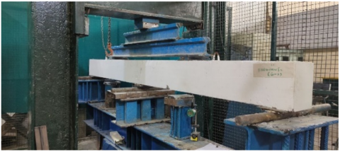
A reaction frame with a hydraulic actuator or a specialized universal testing machine (UTM) was used to test the continuous beams. The setup replicated a two-span continuous beam configuration:
Supports: The constant beam is fixed above three supports, two roller supports (achieved by using steel shift) at a distance 100 from the edge of the beam, and a hinged support at the center of the beam. The span length for each continuous span was 1400 mm (clear span between end support and central support).
Loading Points: At the middle of each continuous span, concentrated loads were applied. This indicates that two-point loads, each equally spaced from the central support, were applied: one at 700 mm from the left end support and another at 700 mm from the proper end support. Steel loading plates were used to distribute the weight to the beam to avoid localized crushing.
Load Application System: To ensure precise measurement of the applied force, the load was applied using a hydraulic jack coupled to a load cell. The calibrated accuracy of the load cell was ±0.5% of the reading.
Instrumentation was positioned carefully to record the beams' structural response: Load cells are positioned between the loading plates and the hydraulic jack to record the applied load. Dial gauge: Used to measure deflections at strategic points. Diameter gauges were usually positioned at the central support and the mid-span of each continuous span (beneath the loading points) to track any settlement or uplift.
2.3.1 Loading procedure
(1) Monotonic loading
The following protocol was used for the eleven specimens that underwent monotonic loading: Loading Mode: Load-controlled means that a steady rise in applied load was made over time. A loading rate of 0.5 kN/min was kept constant for all monotonic experiments. This rate was selected to give enough time to examine the formation of cracks, record data at different load increments, and avoid dynamic impacts. Continuous recordings of the load and deflection readings from the dial gauge and load cells were made for each 5 kN increase in load, whichever occurred more frequently. The test was carried out until the ultimate load was met, the load-carrying capacity significantly decreased, or the specimen showed obvious indications of structural failure (such as severe deflection, concrete crushing, or reinforcement rupturing).
(2) Repeated loading
The four hybrid-reinforced beams and control specimen designated for repeated loading followed a different procedure:
The specimens were subjected to repeated loading and unloading. The load was applied to a load equal to 70% of the ultimate load of the specimen tested under monotonic load, and then the load was removed at the end of the first cycle. After that, this procedure was repeated for nine cycles, and the load was applied to the failure. To track variations in stiffness, permanent deformation, and crack propagation, load and deflection readings were taken at the peak and trough of each load cycle and regular intervals during the cycles. When the reinforcement fractured, the concrete crushed, or there was a noticeable loss of stiffness (such as a permanent deflection that exceeded a critical limit), the repeated loading test was stopped. The maximum load attained in the last cycle before failure was determined to be the ultimate load for these specimens. The test machine is shown in Figure 3.
Figure 3. Testing setup
3.1 Mode of failure and crack patterns
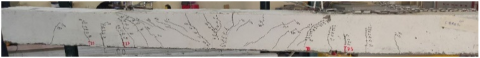
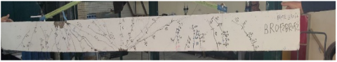
For the control specimen, the first crack appeared at the mid-span of the beam. As the load increased, new cracks formed at the middle support section, and existing cracks were propagated vertically and widened. As the external load increased, new cracks appeared at the positive moment zone. As the load increased, new cracks at the mid-span and middle support region appeared, and the existing cracks propagated quickly to the compression zone. After that, the formation of cracks stopped, and the first crack widened until the flexural failure load occurred at the middle support. The crack pattern and failure mode of specimen BR0F1 are shown in Figure 4.
Figure 4. Crack pattern and failure mode of specimen BR0F1
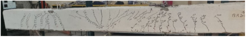
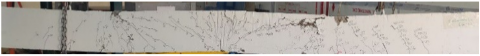
Qualitative insights into the behavior of the structure were obtained by visual inspection and analysis of crack patterns. At a specific stress level, crack initiation and propagation were comparable to control beams for beams containing recycled aggregate. However, following their possibly lower elastic modulus, RAC beams may show significantly wider cracks or a higher density of microcracks at higher loads, especially at the interfacial transition zone. For all beams, the failure mechanisms were mainly flexural, with concrete crushing in the compression zone and, depending on the kind of reinforcement, yielding or rupturing of the tension reinforcement. All specimens showed no signs of premature shear failures, suggesting proper shear design. The crack pattern and failure mode of specimens BR20F1, BR40F1, and BR70F1 are shown in Figures 5-7. The results of these specimens are listed in Table 6.
Figure 5. Crack pattern and failure mode of specimen BR20F1
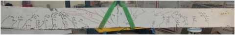
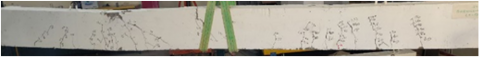
Figure 6. Crack pattern and failure mode of specimen BR40F1
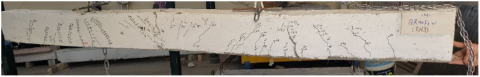
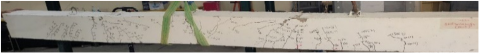
Figure 7. Crack pattern and failure mode of specimen BR70F1
Table 6. Results of the specimen with RCA
|
Specimen |
Pcr (kN) |
Decrease/ Increase in PCR % |
Pu (kN) |
Decrease/ Increase in pu% |
Mode of Failure |
|
BR0F1 |
25 |
--- |
223 |
--- |
flexural |
|
BR20F1 |
30 |
20 |
220 |
-1.3 |
flexural+ compression |
|
BR40F1 |
10 |
-60 |
223 |
0 |
compression |
|
BR70F1 |
15 |
-40 |
211 |
-5.8 |
flexural |
Table 7. Results of the specimen BR40VF1
|
Specimen |
Pcr (kN) |
Decrease/ Increase in PCR% % |
Pu (kN) |
Decrease/ Increase in pu% |
Mode of Failure |
|
BR40VF1 |
40 |
300 |
245 |
9.8 |
flexural |
Figure 8. Crack pattern and failure mode of specimen BR40VF1
For specimen BR40VF1(specimen with steel fiber), the first crack appeared when the load was 40kN at mid-span and an inclined crack at the middle support. Because steel fibers can bridge microcracks and increase the composite material's tensile strength, their usage in concrete raises the initial crack load. When the load gradually increased, a new inclined crack appeared at the right side of the negative moment region. Also, the existing crack propagated, and the first crack widened. As the load increased, the inclined crack at mid-span extended to the compression zone, and the crack at mid-support extended vertically to the compression region until the flexural failure at mid-span and middle support occurred. The crack pattern and failure mode are shown in Figure 8. The result of specimen BR40VF1 is listed in Table 7. It should be noted that after adding steel fiber, the number of cracks decreased due to the ability of steel fiber to arrest the propagation of micro-cracks in the matrix.
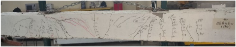
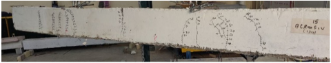
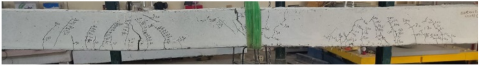
For specimens reinforced with FRP bars that contain recycled aggregate. The first crack in these specimens appeared at the mid-span region. Because FRP has a lower modulus of elasticity than steel, it is less stiff and deforms more under load. Additionally, FRP reinforcement members tend to deflect more than steel-reinforced members under the same load. These factors may be the reason why specimens with FRP exhibit a decrease in the first crack. When loads were applied gradually, new cracks appeared in the middle support region. A new inclined crack appears at the positive moment zone, and the existing crack propagates and widens. At the last stage of load, the formation of cracks was stopped, and the first crack widened until the failure occurred. The crack pattern and failure mode of specimens BGR40VF1, BCR40VF1, and BbfR40VF1 are shown in Figures 9-11. The results of these specimens with FRP are listed in Table 8.
Figure 9. Crack pattern and failure mode of specimen BGR40VF1
Figure 10. Crack pattern and failure mode of specimen BCR40VF1
Figure 11. Crack pattern and failure mode of specimen BbfR40VF1
Table 8. Results of the specimen with FRP bars
|
Specimen |
Pcr (kN) |
Decrease in PCR % |
Pu (kN) |
Decrease pu% |
Mode of Failure |
|
BR40VF1 |
40 |
--- |
245 |
--- |
flexural |
|
BGR40VF1 |
15 |
-62.5 |
170 |
-31 |
compression |
|
BCR40VF1 |
20 |
-50 |
130 |
-47% |
flexural |
|
BbfR40VF1 |
10 |
-75 |
167 |
-32 |
compression |
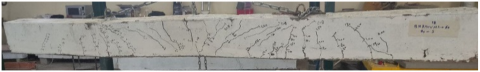
For the specimens with hybrid reinforcement, the first crack in this specimen appeared at the mid-span region. The first crack load was increased in these specimens compared with specimens with FRP bar only. This is attributed to a higher modulus of elasticity of steel than GFRP. When the load was raised, new inclined cracks at the middle support appeared. When the load increased, new cracks at mid-span and middle support appeared, while the existing crack propagated to the compression zone. As the load increased, the new cracks appeared at mid-span, and the existing cracks propagated and widened until failure occurred. The crack pattern and failure mode of specimens with a hybrid reinforcement are shown in Figures 12-14. The results are listed in Table 9.
Figure 12. Crack pattern and failure mode of specimen BHR40VF1(G-S)
Figure 13. Crack pattern and failure mode of specimen BHR40VF1(C-S)
Figure 14. Crack pattern and failure mode of specimen BHR40VF1(bf-S)
Table 9. Test results of the specimens with the hybrid reinforcement
|
Specimen |
Pcr (kN) |
Increase in PCR % |
Pu (kN) |
Increase pu% |
Mode of Failure |
|
BR40VF1 |
40 |
--- |
245 |
--- |
flexural |
|
BGR40VF1 |
15 |
--- |
170 |
--- |
compression |
|
BHR40VF1(G-S) |
20 |
33% |
210 |
23.5% |
compression |
|
BCR40VF1 |
20 |
--- |
130 |
--- |
flexural |
|
BHR40VF1(C-S) |
20 |
0 |
200 |
54% |
flexural |
|
BbfR40VF1 |
10 |
--- |
167 |
--- |
compression |
|
BHR40VF1(bf-S) |
30 |
200% |
210 |
20.5% |
compression |
For specimens under repeated load. In these specimens, the first crack appeared in the first cycle at the middle of the span on the left side of the beam. As the load increased, a new crack at the middle support appeared. After that, the cracks continued to occur during the first cycle, and then the cracks stopped appearing in the other cycles and continued to propagate and widen in the different cycles. After 10 cycles, the specimens were loaded up to failure. The failure mode is shown in the Figures 15-18. The test results are listed in Table 10.
Figure 15. Crack pattern and failure mode of the specimen BR0F2
Figure 16. Crack pattern and failure mode of specimen BHR40VF2(G-S)
Figure 17. Crack pattern and failure mode of specimen BHR40VF2(C-S)
Figure 18. Crack pattern and failure mode of specimen BHR40VF2(bf-S)
Table 10. Results of specimens under repeated load
|
Specimen |
Pmax.Re (kN) |
(P max.Re/PU.mon)*100 |
Pu.Re (kN) |
Decrease % |
Type of Failure |
|
BR0F2 |
155 |
70% |
220 |
-1% |
compression +shear |
|
BHR40VF2 M1.0(G-S) |
147 |
70% |
200 |
4.7% |
crushing |
|
BHR40VF2 M1.0(C-S) |
140 |
70% |
170 |
15% |
compression + flexural |
|
BHR40VF2 M1.0(bf-S) |
147 |
70% |
207 |
1.4% |
flexural |
3.2 Load-midspan deflection
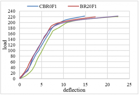
Deflection at two mid-spans (left and right mid-spans) was measured by using a dial gauge. Because of the inherent characteristics of the old mortar that is still connected and its increased porosity, concrete that contains recycled aggregates often has a lower modulus of elasticity. This may result in less rigidity under load and somewhat greater deflections. If the final load decrease were slight, the results in Table 11 would probably indicate a tendency of rising deflection and decreasing stiffness with larger recycled aggregate replacement ratios, but maybe to a small level. This would imply a slight effect on serviceability that may be lessened with thoughtful design. The load-deflection curves for beams with different replacement ratios are shown in Figure 19. Until the first cracking point, which happened at a stress of 25 kN, the control specimen, BR0F1, showed a linear load-deflection response. The deflections of the beams with 20%, 40%, and 70% RCA were approximately 16.5%, 51%, and 52%, respectively, greater than the deflection of the control beam (BR0F1). In the control beam (BR0F1), the crack spread to the compression zone, causing a rapid increase in deflection.
Table 11. Details the load and deflection for specimens under monotonic load
|
Specimen |
Pu (kN) |
Increase and Decrease %in pu |
Max Deflection (mm) |
Service deflection(mm) (0.65pu) |
|
BR0F1 |
223 |
--- |
14.8 |
6.2 |
|
BR20F1 |
220 |
-1.3% |
17.25 |
6 |
|
BR40F1 |
223 |
--- |
22.35 |
6 |
|
BR40VF1 |
245 |
10% |
22.39 |
5.1 |
|
BR70F1 |
211 |
-5.38% |
22.4 |
6.5 |
|
BGR40VF1 |
170 |
-30.6% |
22.36 |
11 |
|
BHR40VF1(G-S) |
210 |
23.5% |
20.3 |
5.9 |
|
BCR40VF1 |
130 |
-47% |
17.59 |
9.4 |
|
BHR40VF1(C-S) |
200 |
54% |
23.11 |
5.8 |
|
BbFR40VF1 |
167 |
-32% |
17.15 |
10 |
|
BHR40VF1(bF-S) |
210 |
25.7% |
26.71 |
6.5 |
Figure 19. Effect of replacement ratio on the load-deflection curve
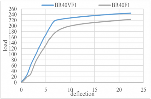
In contrast, RCA-containing beams produced more cracks than the control beam. This increased cracking contributed to the greater deflections noticed in the RCA sample. However, adding steel fiber decreased deflection by about 15%, as shown in Figure 20. As shown in Table 11, The ultimate load capacity of the continuous beams was generally somewhat reduced as the replacement ratio of recycled aggregate was increased, as shown in Table 11. The 70% replacement ratio, roughly 5.38% lower than the control specimens, showed the most significant reduction in ultimate load. Even smaller, insignificant decreases in ultimate load were seen for the 20% and 40% replacement ratios. Because recycled aggregates are often of inferior quality and have a higher porosity than native aggregates, this modest reduction may result in a weaker interfacial transition zone (ITZ) inside the concrete matrix.
However, the extent of this reduction suggests that the influence on ultimate load is negligible and suitable for real-world applications for the structural elements and loading conditions under investigation. Adding steel fiber (with a volume fraction of about 1%) in specimen BR40VF1 led to an increase in ultimate load of about 10% compared with BR40F1.
Figure 20. Effect of steel fiber on load-deflection curve
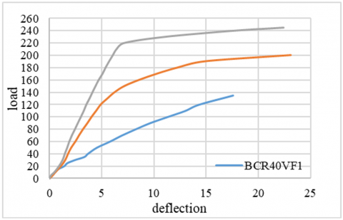
Figure 21. Effect of changing the type of reinforcement on load-deflection
Figure 22. Effect of using hybrid reinforcement (GFRP+steel) on load-deflection response
Figure 23. Effect of using hybrid reinforcement (CFRP+steel) on the load-deflection curve
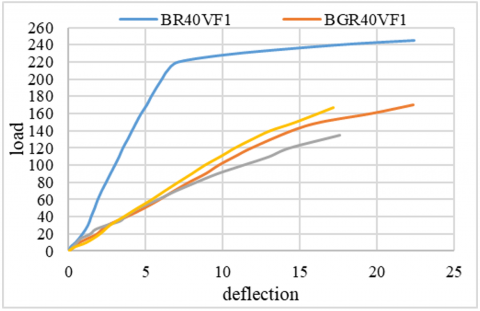
For the specimens reinforced with FRP bars that contain recycled aggregate. From Figure 21, it can be observed that the reinforced beams with CFRP, BFRP, and GFRP led to a higher increase in deflection. The rise in deflection is about 115%, 84%, and 85% for the beams BGR40VF1, BCR40VF1, and BbfR40F1V, respectively, compared with BR40VF1(specimen reinforced by steel). One possible explanation for the increased deflection seen in the FRP-reinforced beams is that there are two main reasons for the noticeably greater deflection seen in the FRP-reinforced beams:
1. Slippage between FRP and Concrete: FRP bars often have different surface properties and a lower modulus of elasticity than steel, resulting in more bond slip between the surrounding concrete and the FRP reinforcement. Greater deformations in the beam under load are a result of this slippage.
2. Debonding Failure: Another essential factor is the propensity for debonding failure, which occurs when the bond between the FRP bar and the concrete is broken. The composite action between the concrete and reinforcement is weakened once debonding starts and spreads, which results in a significant decrease in stiffness and, as a result, a considerable rise in deflection.
When FRP was utilized to reinforce the specimens, the ultimate load decreased. The decrease in ultimate load is about 30.6%,31.89%, and 47% for the beams BGR40VF1, BbfR40VF1, and BCFRP, respectively, compared with BR40VF1. All specimens with RCA reinforced by FRP bars exhibited lower ultimate load and higher deflection compared with beams with RCA reinforced by steel bars.
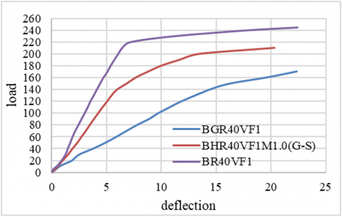
For the beam with a hybrid reinforcement, adding one GFRP for the bottom and top reinforcement with the main reinforcement steel bars led to an improvement in the stiffness and recorded a decrease in deflection of about 46.16% for the beam BHR40VF1(G-S), compared with BGR40VF1.On the other hand, using a hybrid reinforcement led to an increase in the ultimate load of about 23.5% for the beams BHR40VF1(G-S) compared with BGR40VF1. The effect of using hybrid reinforcement is exhibited in Figure 22.
In the other group, the one CFRP at the top and bottom reinforcement with a steel bar. From Figure 23, it can be noticed that using a hybrid reinforcement led to a decrease in the deflection. A reduction in deflection is about 38.29% for the beam BHR40VF1(C-S) compared with BCR40VF1. The increase in ultimate load for the beam with a hybrid reinforcement is about 53.8% compared with the specimens BCHR40VF1.
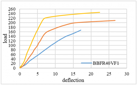
The specimens BHR40VF1(bf-S) give a reduction in deflection of about 35% and 20%, respectively, compared with specimen BbfR40VF1. Introducing hybrid reinforcement, which combined steel bars with BFRP (Basalt Fiber Reinforced Polymer) bars, significantly increased the beams' ultimate load-carrying capacity. Compared to beam BbfR40VF1, beam BHR40VF1(bf-S) demonstrated improvements in ultimate load of 25.7%. The effect of using hybrid reinforcement is exhibited in Figure 24.
Figure 24. Effect of using hybrid reinforcement (BFRP+steel) on load-deflection behavior
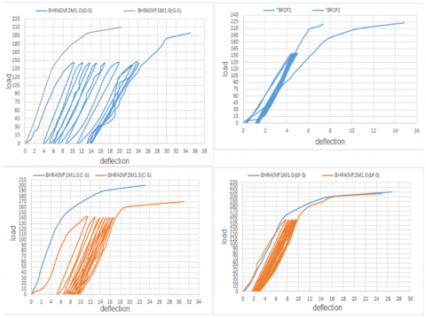
The result showed that the specimen tested under repeated load exhibited a reduction in ultimate load compared with the specimen tested under static load. During the loading and unloading process, cracks mainly appeared in the first cycle, while in another cycle, the existing cracks extended, which led to an increase in deflection. The increase in max deflection was about 72% and 32% for the specimens BHR40VF2(G-S) and BHR40VF2(C-S), respectively, compared with the identical specimens tested under static load. The ultimate load decreased by 1%,4.7%,15%, and 1.4% for specimens BR0F2, BHR40VF2(G-S), BHR40VF2(C-S), and BHR40VF2(bf-S), respectively, compared with the same specimen tested under monotonic load. The load-deflection specimens tested under repeated load are shown in Figure 25.
Figure 25. Load-deflection for the specimen under static and repeated load
For recycled aggregate concrete beams, hybrid reinforcement—a combination of steel bars and fiber-reinforced polymer—offers several benefits. Excellent corrosion resistance from FRP bars increases durability, particularly in harsh settings where recycled materials may increase the permeability of concrete. Steel reinforcement's ductility and consistent yielding behavior enhance energy absorption and crack control.
The hybrid system utilizes the complementary qualities of both materials in repeated loading situations. While FRP bars keep their tensile capacity without deteriorating due to corrosion, steel reinforcement aids in maintaining structural integrity through plastic deformation, potentially increasing service life.
There are, nevertheless, certain restrictions. Under cyclic loads, FRP and steel's differing bond and mechanical properties could result in complicated stress distributions and possible early debonding or slippage. Additionally, stiffness and deflection control may be impacted by certain FRP types' lower modulus of elasticity compared to steel. More research is required to optimize hybrid reinforcement design for fatigue performance, as the current study found a decrease in ultimate load during repeated loading.
Hybrid reinforcement offers a viable method for environmentally friendly concrete constructions; however, it is crucial to assess material interaction and long-term behavior under cyclic stresses carefully.
3.3 Toughness
The ability of a material to withstand energy in the plastic domain until it ruptures is referred to as its toughness. Evaluating this parameter can be challenging. However, one method is to divide the volume of the tested sample by the total area (A) enclosed by the load-deflection or stress-strain curve. The energy per unit volume that a material can sustain before rupture is an indicator of its toughness. This method has been applied to assess the toughness for all beams listed in Table 12 [22].
From Table 12, it can be shown that the toughness decreased with an increase in the replacement ratio of RCA. The decrease in toughness is about 4.8%, 14.4%, and 35.5% for beams BR20F1, BR70F1, andBR70F1respectively compared with specimen BR0F1.However, adding steel fiber led to an improvement in the toughness. The increase in toughness is about 95% for specimen BR40VF1 compared with specimen BR40F1. This performance can be explained by the fact that Steel fibers serve as bridges across concrete microcracks, which can occur even under relatively little load. This bridging action takes more energy to fracture the material, preventing cracks from propagating and widening. This is the main way that steel fibers increase toughness. Using FRP bars to reinforce the specimens’ results in a decrease in toughness. There was a decrease in the toughness of about 51%,69%, and 66% for specimens BGR40VF1, BCR40VF1, and BbfR40VF1, respectively, compared with specimen BR40VF1. This is attributed to the Different bonding behaviors and more abrupt failure modes, such as delamination or rupture, which are possible for FRP bars. These sudden failures limit the energy absorption capability. Compared to steel, FRP bars usually have a lower modulus of elasticity. This indicates that, although they deform more under the same stress, the deformation is mostly elastic rather than plastic. This elastic deformation does not offer the same energy absorption properties as plastic deformation. However, using hybrid reinforcement led to improved toughness. The increase in toughness was about 54%,138%, and 181% for specimen BHR40VF1(G-S), BHR40VF1(C-S), and BHR40VF1(bf-S) respectively compared with specimens BGR40VF1, BCR40VF1, and BbfR40VF1respectively.
Table 12. Toughness for all beams under static load
|
Specimen |
Toughness (kN/mm) |
Increase/Decrease % |
Note |
|
Group one |
|||
|
BR0F1 |
2700 |
--- |
control |
|
BR20F1 |
2568 |
-4.8 |
|
|
BR40F1 |
2311 |
-14.4 |
|
|
BR70F1 |
1742 |
-35.5 |
|
|
BR40VF1 |
4509.4 |
95 |
|
|
Specimen with FRP bar |
|||
|
BR40VF1 |
4509 |
--- |
control |
|
BGR40VF1 |
2180 |
-51 |
|
|
BCR40VF1 |
1395 |
-69 |
|
|
BbfR40VF1 |
1511 |
-66 |
|
|
Group four |
|||
|
BR40VF1 |
2180 |
--- |
control |
|
BGR40VF1 |
4509 |
--- |
control |
|
BHR40VF1(G-S) |
3370 |
54 |
|
|
Group five |
|||
|
BR40VF1 |
4509 |
--- |
control |
|
BCR40VF1 |
1395 |
--- |
control |
|
BHR40VF1(C-S) |
3327.9 |
138 |
|
|
Group six |
|||
|
BR40VF1 |
4509 |
--- |
control |
|
BbfR40VF1 |
1511 |
--- |
control |
|
BHR40VF1(bf-S) |
4249 |
181 |
|
3.4 Crack width
The crack width was measured using a crack meter for a crack width less than 0.5mm; otherwise, Vernia was used. The first crack initiated at mid-span was monitored during all stages of loading up to failure to record the crack width history.
Table 13 shows that in the specimen with the different replacement ratios of RCA, the crack width for the specimen with RCA is close to the crack width of the specimen without RCA. However, at a late loading stage, the crack width for the specimen with RCA increased compared to specimen BR0F1. The increase is about 38%, 61%, and 168% for the specimens BR20F1, BR40F1, and BR70F1, respectively. The inherent disadvantages of RCA, such as a weaker ITZ, higher porosity, and lower stiffness, render RCA concrete more prone to crack widening at later loading stages, which is why the crack width increased. These elements, along with decreased aggregate interlock and greater shrinkage, cause wider cracks in RCA concrete. Despite that, adding steel fiber decreased the crack width by about 57% compared with specimens without steel fiber. This is due to the steel fibers functioning as bridges between emerging cracks. This bridging effect prevents cracks from spreading by transmitting tensile stress. Incorporating steel fibers enhances tensile strength, necessitating a greater stress level to originate and propagate a fracture, resulting in smaller cracks—using FRP bars to reinforce the continuous beam led to increased crack width. The increase in crack width is about 290%, 290%, and 178% for specimens BGR40VF, BCR40VF, and BbfR40VF1respectively compared with specimen BR40VF1. This is due to the decreased rigidity of FRP, which allows for more elongation under load, resulting in wider cracks.
Table 13. Maximum crack width for all specimens
|
Specimen |
Maximum Crack Width |
Decrease-Increase in Max-Crack Width |
|
BR0F1 |
0.72 |
--- |
|
BR20F1 |
1.00 |
38% |
|
BR40F1 |
1.16 |
61% |
|
BR70F1 |
1.93 |
168% |
|
BR40VF1 |
0.5 |
-57% |
|
BGR40VF1 |
1.95 |
290% |
|
BHR40VF1(G-S) |
0.89 |
-54% |
|
BCR40VF1 |
1.96 |
290% |
|
BHR40VF1(C-S) |
1.01 |
-48% |
|
BbfR40VF1 |
1.39 |
178% |
|
BHR40VF1(bf-S) |
0.81 |
-42% |
|
BR0F2 |
1.16 |
61% |
|
BHR40VF2(G-S) |
2.33 |
161% |
|
BHR40VF2(C-S) |
1.02 |
0% |
|
BHR40VF2(bf-S) |
1.56 |
92% |
Additionally, since FRP doesn't give, there is no stress redistribution to control the crack width. Because of its weaker bond, the FRP slips more easily and splits more widely. The effect of hybrid reinforcement decreases crack width by about 55% for specimen BHR40VF1(G-S) compared with specimen BGR40VF1. The specimen BHR40VF1(C-S) decreased the crack width by about 48% compared with specimen BCR40VF1. The specimen BHR40VF1(bf-S) decreases crack width by about 42% compared with specimen BbfR40VF1. Hybrid reinforcing is thought to reduce cracking width because the steel has a higher modulus of elasticity and gives the beam more stiffness, which limits overall deformation. The specimens BROF2, BHR40VF2M1.0(G-S), BHR40VF2M1.0(C-S), and BHR40VF2M1.0(bf-S) were tested under repeated load, giving an increase in crack width compared with the identical specimens tested under static load. This is attributed to the decreased stiffness of the beam during repeated loading and unloading cycles.
This paper includes experimental work on the structural behavior of recycled aggregate concrete continuous beams with hybrid reinforcement under monotonic and repeated loads. The following conclusion can be drawn:
1- When compared to the identical specimen without steel fiber, the addition of steel fiber resulted in a 300% increase in cracking load, a 38% decrease in deflection, and a 10% improvement in ultimate.
2- Although there was no discernible drop in ultimate load capacity, using recycled aggregate in the concrete at different replacement ratios led to a notable increase in beam deflection of up to 51%. This behavior is explained by the fact that the yielding of the steel reinforcement primarily controls the flexural failure mode rather than the concrete's compressive strength, which is usually more sensitive to the recycled aggregate quality.
3- The findings show that the best performance was achieved by beams with a 40% RCA replacement ratio (BR40F1). They exceeded the values found in the 70% replacement beam. Still, they also achieved the same ultimate load as the control specimen (BR0F1), showed less deflection than the 70% replacement beam (BR70F1), and had compressive strength, tensile strength, flexural strength, and modulus of elasticity that were comparable to the 20% replacement beam (BR20F1). Therefore, a 40% RCA replacement ratio is the most effective and cost-efficient option for future specimens.
4- When compared to their steel-reinforced counterparts, reinforced concrete beams using Carbon Fiber Reinforced Polymer (CFRP), Basalt Fiber Reinforced Polymer (BFRP), and Glass Fiber Reinforced Polymer (GFRP) bars showed noticeably greater deflections.
In particular, compared to the steel-reinforced specimen, BR40VF1, deflections increased by roughly 115% for beam BCR40VF1 (CFRP-reinforced), 84% for beam BbfR40F1V (BFRP-reinforced), and 85% for beam BGR40VF1 (GFRP-reinforced). Two main reasons for the noticeably greater deflection in the FRP-reinforced beams are the slope between FRP and Concrete and debonding failure.
5- Compared to steel-reinforced beams (BR40VF1), a significant reduction in ultimate load capacity was noted when FRP (Fiber fiber-reinforced polymer) was utilized as the only reinforcement in the specimens. In particular, the final load dropped by roughly 30.6% for the GFRP-reinforced beam BGR40VF1, 31.89% for the BFRP-reinforced beam BbfR40VF1, and 47% for the CFRP-reinforced beam BCFRP.
6- Using hybrid reinforcement led to a decrease in deflection of about 46.16 and an increase in ultimate load of about 23.5% for specimen BHR40VF1(G-S) compared with specimen BGR40VF1.
7- Using CFRP and steel as a hybrid reinforcement led to a reduction in deflection of about 38% and an increase in ultimate load of about 53% for specimen BHR40VF1(C-S) compared with specimen BCR40VF1.
8- Using BFRP and steel as a hybrid reinforcement led to a reduction in deflection of about 35% and an increase in ultimate load of about 25.7% for specimen BHR40VF1(bf-S) compared with specimen BbfR40VF1.
9- The decrease in ultimate load when the specimens are exposed to repeated load is about 1%, 4.7%, 15%, and 1.4% for the specimens BR0F2, BHR40VF2(G-S), BHR40VF2(C-S), and BHR40VF2(bf-s), respectively, compared with the identical specimens under monotonic load
10- Using recycled aggregate led to an increase in crack width of about 38%, 61%, and 168% for the specimens BR20F1, BR40F1, and BR70F1 compared with specimen BR0F1.
11- Using hybrid reinforcement led to a decrease in the crack width of about 54%, 48%, and 42% for the specimens BHR40VF1(G-S), BHR40VF1(C-S), and BHR40VF1(bf-S), respectively, compared with specimens BGR40VF1, BCR40VF1, and BbfR40VF1.
Engineering benefits: Include promoting sustainable construction through recycled materials, improving load performance with hybrid reinforcement, and enhancing durability under service loads—making this method suitable for long-span, durable concrete structures.
Future research is necessary in several crucial areas to fully realize the promise of hybrid-reinforced concrete structures and further develop their use, especially those incorporating recycled aggregates.
5.1 Optimizing hybrid reinforcement configuration and ratios for enhanced performance
Strategic Positioning in the Cross-Section: Particular hybrid configurations were used in this investigation. Future research should methodically examine the best locations for steel and various FRP types (GFRP, CFRP, and BFRP) inside the beam cross-section. For instance, investigating situations in which GFRP or BFRP are used for other regions and higher modulus CFRP bars are carefully positioned in crucial tension zones for strength and stiffness, or the precise placement of steel to guarantee a controlled ductile failure and improved crack management.
Performance-Based Reinforcement Ratios: Future research should concentrate on creating methods to ascertain the ideal steel ratios to different types of FRP based on desired performance characteristics rather than just reaching a specific strength. The hybrid ratio must be modified to accomplish particular ductility indices, target fracture width limitations at service loads, regulate deflections within stringent bounds, and improve long-term fatigue life under particular loading spectra.
Study of Hybrid Fiber Reinforcement: Although 1% steel fiber was used in this study, additional research could examine the potential benefits of integrating various discrete fiber types (such as synthetic, natural, or hybrid blends of fibers) with hybrid bar reinforcement in the concrete matrix. This may result in additional improvements in durability, impact resistance, and post-cracking behavior.
5.2 Long-term performance and durability of hybrid systems with recycled aggregates
Fatigue Life Prediction Models: The study found that hybrid beams had a 15% reduction in ultimate load during repeated loading. More complex fatigue models for hybrid-reinforced concrete must be developed and validated in future studies, considering the intricate interactions between the different fatigue behaviors of FRP (brittle rupture) and steel (yielding and crack propagation) at different stress ranges and frequencies. This is essential for precise life prediction of structures under dynamic stresses.
Bond Durability in Aggressive Environments: Examine how long-lasting the bond between recycled aggregate concrete and different types of FRP and steel is under a combination of environmental stressors (such as alkali-silica reaction, prolonged moisture, freeze-thaw cycles, chloride infiltration, and high temperatures). The pore structure and chemical environment of concrete may change when recycled aggregate is used, which could impact bond performance.
5.3 Enhanced predictive tools and numerical modeling
Comprehensive Constitutive Models: Create and improve sophisticated numerical models that faithfully depict the intricate constitutive behavior of recycled aggregate concrete reinforced with hybrid materials, for example, by employing finite element analysis. Bond-slip relationships, cracking, post-cracking behavior under monotonic and cyclic loads, and the special features brought about by RCA should all be considered in these models.
Serviceability Prediction Under Fatigue: Improve numerical techniques to precisely forecast long-term deflections and crack widths in recycled aggregate concrete elements reinforced with hybrid reinforcement, considering the effects of fatigue-induced damage buildup, creep, and shrinkage.
5.4 Comprehensive testing and standardization initiatives
Larger Scale Testing: To validate laboratory results and tackle real-world construction issues, go beyond beam specimens and examine the behavior of full-scale structural elements (such as slabs, columns, and beam-column junctions) utilizing recycled aggregates and hybrid reinforcement.
By methodically addressing these research avenues, the engineering community can advance toward a more assured, adequate, and broad use of hybrid reinforcement in recycled aggregate concrete structures. This will guarantee improved performance, durability, and sustainability in the building sector.
|
% |
Percentage |
|
Fcu |
Compressive strength of concrete (cube) MPa |
|
Fc' |
Compressive strength of concrete (cylinder), MPa |
|
Ft |
Tensile strength of concrete, MPa |
|
Fy |
Steel yield stress, MPa |
|
kg/m3 |
Kilogram per meter cube |
|
Kn |
Kilo Newton |
|
L/m3 |
Liter per meter cube |
|
Mm |
Millimeter |
|
MPa |
Mega Pascal |
|
w/c |
Water cement ratio |
|
Greek symbols |
|
|
Ø |
Diameter of reinforcement bar, mm |
|
Subscripts |
|
|
B |
Beam |
|
R |
Percentage ratio of recycled aggregate |
|
0% |
Zero percentage ratio |
|
20% |
Twente percentage ratio |
|
40% |
Forty percent ratio |
|
70% |
Seventy percent ratios |
|
100% |
One hundred percent ratios |
|
F |
Refers to flexural |
|
1 |
Refers to the monotonic load |
|
2 |
Refers to repeated load |
|
V |
Refers to steel fiber |
|
C |
Carbon fiber |
|
bf |
Basalt fiber |
|
G |
Glass fiber |
|
H |
Hybrid reinforcement |
[1] Ozbakkaloglu, T., Gholampour, A., Xie, T. (2018). Mechanical and durability properties of recycled aggregate concrete: effect of recycled aggregate properties and content. Journal of Materials in Civil Engineering, 30(2): 04017275. https://doi.org/10.1061/(ASCE) MT.1943-5533.0002142
[2] Safiuddin, M., Alengaram, U.J., Rahman, M.M., Salam, M.A., Jumaat, M.Z. (2013). Use of recycled concrete aggregate in concrete: a review. Journal of Civil Engineering and Management, 19(6): 796-810. https://doi.org/10.3846/13923730.2013.799093
[3] Zhou, C., Chen, Z. (2017). Mechanical properties of recycled concrete made with different types of coarse aggregate. Construction and Building Materials, 134: 497-506. https://doi.org/10.1016/j.conbuildmat.2016.12.163
[4] Malešev, M., Radonjanin, V., Marinković, S. (2010). Recycled concrete as aggregate for structural concrete production. Sustainability, 2(5): 1204-1225. https://doi.org/10.3390/su2051204
[5] Ftnan, A., Makki, R. (2022). Behavior of recycled aggregate concrete beams strengthened with FRP. Kufa Journal of Engineering, 13(4): 13-24. https://doi.org/10.30572/2018/KJE/130402
[6] Al-Azzawi, A.A. (2016). Mechanical properties of recycled aggregate concrete. ARPN Journal of Engineering and Applied Sciences, 11(19): 11233-11238.
[7] Mohammed, N., Sarsam, K., Hussien, M. (2018). The influence of recycled concrete aggregate on the properties of concrete. MATEC Web of Conferences, 162: 02020. https://doi.org/10.1051/matecconf/201816202020
[8] Kabashi, N., Avdyli, B., Krasniqi, E., Këpuska, A. (2020). Comparative approach to flexural behavior of reinforced beams with GFRP, CFRP, and steel bars. Civil Engineering Journal, 6(1): 50-59. https://doi.org/10.28991/cej-2020-03091452
[9] Fan, C.C., Huang, R., Hwang, H., Chao, S.J. (2015). The effects of different fine recycled concrete aggregates on the properties of mortar. Materials, 8(5): 2658-2672. https://doi.org/10.3390/ma8052658
[10] Almahmood, H., Ashour, A., Sheehan, T. (2020). Flexural behaviour of hybrid steel-GFRP reinforced concrete continuous T-beams. Composite Structures, 254: 112802. https://doi.org/10.1016/j.compstruct.2020.112802
[11] Kara, I.F., Ashour, A.F., Köroğlu, M.A. (2015). Flexural behavior of hybrid FRP/steel reinforced concrete beams. Composite Structures, 129: 111-121. https://doi.org/10.1016/j.compstruct.2015.03.073
[12] Lin, C.H., Chien, Y.M. (2000). Effect of section ductility on moment redistribution of continuous concrete beams. Journal of the Chinese Institute of Engineers, 23(2): 131-141. https://doi.org/10.1080/02533839.2000.9670531
[13] Ashour, A.F., Habeeb, M.N. (2008). Continuous concrete beams reinforced with CFRP bars. Proceedings of the Institution of Civil Engineers-Structures and Buildings, 161(6): 349-357. https://doi.org/10.1680/stbu.2008.161.6.349
[14] Kou, S.C., Poon, C.S. (2009). Properties of self-compacting concrete prepared with coarse and fine recycled concrete aggregates. Cement and Concrete Composites, 31(9): 622-627. https://doi.org/10.1016/j.cemconcomp.2009.06.005
[15] Yoon, Y.S., Yang, J.M., Min, K.H., Shin, H.O. (2011). Flexural strength and deflection characteristics of high-strength concrete beams with hybrid FRP and steel bar reinforcement. Special Publication, 275: 1-22. https://doi.org/10.14359/51682414
[16] Hameed, S.A. (2013). Mechanical properties of fiberous recycled aggregate concrete. Tikrit Journal of Engineering Sciences, 20(4): 42-52. https://doi.org/10.25130/tjes.20.4.05
[17] Seara-Paz, S., González-Fonteboa, B., Martínez-Abella, F., Eiras-López, J. (2018). Flexural performance of reinforced concrete beams made with recycled concrete coarse aggregate. Engineering Structures, 156: 32-45. https://doi.org/10.1016/j.engstruct.2017.11.015
[18] Lu, C.H., Li, H., Xu, K., Xuan, G.Y., Abdullah, W. (2020). Experimental study of flexural behavior and serviceability of hybrid concrete beams reinforced by steel and G/BFRP bars. IOP Conference Series: Materials Science and Engineering, 770(1): 012007. https://doi.org/10.1088/1757-899X/770/1/012007
[19] Hassan, S.A., Faroun, G.A. (2020). Effect of loading level of hybrid reinforced concrete deep beams under repeated loading. Al-Esraa University College Journal for Engineering Sciences, 2(1): 15-38. https://doi.org/10.70080/2790-7732.1010
[20] Diab, H., Khaled, T., Rashwan, M. (2021). Flexural behavior of RC continuous T-beams reinforced with hybrid CFRP/steel bars (experimental and numerical study). JES. Journal of Engineering Sciences, 49(2): 215-247.
[21] ASTM A615/A615M-22. (2024). Standard specifications for deformed and plain carbon structural steel bars for concrete reinforcement. https://store.astm.org/a0615_a0615m-22.html.
[22] AL-Turaihi, A.A., Al-Katib, H.A. (2024). Behavior of hybrid reinforced concrete beams on flexural strength. Kufa Journal of Engineering, 15(2): 27-38. https://doi.org/10.30572/2018/KJE/150203