Fatima Zohra Diar*![]() | Youssef Benbouras
| Youssef Benbouras![]() | Mohammed Ouabdou
| Mohammed Ouabdou![]() | Benaissa El Fahime
| Benaissa El Fahime![]() | Mohammed Radouani
| Mohammed Radouani![]()
© 2025 The authors. This article is published by IIETA and is licensed under the CC BY 4.0 license (http://creativecommons.org/licenses/by/4.0/).
OPEN ACCESS
The use of composite materials has emerged as a critical alternative to traditional metallic structures, particularly in aerospace engineering where high strength-to-weight ratio and structural integrity are essential. This paper presents an analytical and experimental investigation of delamination in T300-3000 epoxy carbon fiber composites subjected to three-point bending tests. The main contribution lies in the development of a predictive model integrating Classical Plate Theory (CPT) with the Tsai-Hill failure criterion to assess delamination initiation and propagation. A specially designed multilayered laminate was tested under standardized conditions, and a strong correlation was observed between experimental results and model predictions, with a deviation of less than 8% in peak load estimations. The mechanical properties of the epoxy interface, along with Fiber Volume Fraction (FVF), were also taken into account for a more accurate representation of interlaminar stress distribution. The study highlights the limitations of the Tsai-Hill criterion, particularly in differentiating tensile and compressive transverse failures, and recommends the inclusion of higher-order shear deformation theories in future work. The proposed approach offers valuable insights into the structural behavior of composites under flexural loading and can guide the design of more damage-tolerant aerospace components through better laminate configuration and non-destructive evaluation strategies.
T300-3000 epoxy composites, delamination modeling, composite structural analysis, three-point bending, Tsai-Hill failure criterion, classical plate theory
A composite material is formed by mixing two or more separate components to gain improved qualities. It is often made up of a matrix (polymer, metal, or ceramic) and reinforcements (carbon, glass, or aramid fibers, or ceramic particles). The matrix serves as a continuous phase that surrounds and binds the reinforcements together, whilst the reinforcements give the material unique qualities like mechanical strength and lightness. Composite materials are widely employed in a range of industries due to their exceptional mechanical qualities, including aerospace, automotive, civil engineering, and sports [1].
Among these sectors, one of the most important uses of composite materials is in aerospace. Composites have supplanted conventional metallic structures in aircraft fuselages, wings, tail sections, and engine components because of their excellent strength-to-weight ratio, fatigue resistance, and corrosion resistance. Carbon fiber-reinforced polymer (CFRP) composites are frequently utilized in contemporary aircraft to lower weight, increase fuel economy, and increase flight range. Composites are also used in satellite and spacecraft structures because of their great mechanical strength and thermal stability, which provide dependability in harsh conditions. Composite materials are widely used in aerospace, which greatly improves overall operational efficiency, performance, and durability. Their vulnerability to failure modes like delamination, however, continues to be a serious worry.
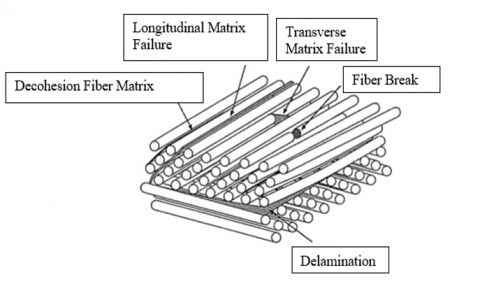
The defects in composite materials can be differentiated into intra-laminar and inter-laminar damage that occur respectively by fiber and matrix damage and primarily by delamination. On microscopic scales, they manifest themselves as micro-cracking and micro-voids, whereas on macroscopic scales such damage appears in the form of delamination, macro-matrix cracking, fiber-matrix decohesion, or fiber failure. These defects involve air bubbles, voids, foreign inclusions, cracks, fiber defects (breakage or delamination), matrix defects (porosity or insufficient polymerization), variations in thickness and density, as well as manufacturing faults, any of which can alter the mechanical properties and durability of composites. This brings to light the emergence of non-destructive testing (NDT) methods that can be used to identify and evaluate structural integrity [2, 3]. These typical defects are illustrated in Figure 1, which summarizes the most common internal flaws observed in composite materials.
Delamination, a common defect in composite materials, includes the discontinuous carbon-epoxy composites in its ranks. This occurs due to the presence of forces that separate the layers of composite material and form a zone of weakness, which can significantly reduce load-bearing capacity and mechanical performance. This becomes extremely crucial in aerospace applications as delamination can threaten the integrity of primary structures, such as aircraft wings, fuselages, and engine nacelles, where safety and durability are of utmost importance.
Delamination may arise due to multiple factors, such as too much mechanical stress, impact damage, poor adhesion between layers, external environmental conditions, or manufacturing defects. Because of the demanding safety and operational requirements in the aerospace industry, it is imperative to detect and mitigate delamination. As they allow for the early detection of delamination and the mitigation of possible structural failures, advanced non-destructive testing methods like ultrasonic C-scan, thermography, and digital image correlation are widely practiced [4, 5].
Fracture criteria for composite materials provides useful input for the assessment of strength and prediction of composite failure. The Tsai-Hill criterion estimates strength as a function of principal stresses to derive ultimate stress at failure in an off-axis stress state [6-9]. Similarly, Tsai-Wu criteria serve to evaluate the strength of CFRP composites subjected to different stress conditions [6, 8-14]. In broad terms, interaction in stress components exploits the different material orientations under the respective loading conditions. Composite material failure is then predicted using these criteria.
Other criteria worthy of consideration for composite material failure assessment are the Tsai-Hill failure criterion, the Tsai-Wu failure criterion, the Barlat failure criterion, maximum stress criterion, maximum strength criterion, damage factor, Tsai-Hill-based failure criterion, and Hoffman failure criterion [13-16]. Each criterion has specific conditions and inequalities for the prediction of fiber-dominated, inter-fiber, or other types of failure modes.
The Hashin criterion [14, 15, 17, 18], for instance, distinguish between fiber-dominated and inter-fiber failure modes by taking into consideration the interaction of the different different type stresses in the particular material. In a similar vein, the Puck criterion predicts failure due to the interaction of stress components to allow a correct assessment of composite strength. Other than that, the Schurmann criterion uses phenomenological models to accurately predict composite laminate failures accounting for different failure modes and interaction between the stress components. These criteria are to be used to evaluate composite failure mechanisms under different loading conditions and are often compared to assess their effectiveness at predicting experimental results. Crucial to the design, manufacture, and use of composite materials, they ensure their strength, durability, and performance under various loadings.
Higher-order quasi-3D kinematic plate theory accounts for shear deformation effects. The peridynamic model based on conjugate bonds provides a fresh view for studying the mechanical behavior of laminated composite materials. It embodies the interactions between the constituent layers of the laminate with anisotropic and heterogeneous properties, confinement effects, delamination, and interfacial deformation phenomena [19, 20]. Classical laminated plate theorem constitutes a solid foundation in structural engineering for the assessment of mechanical behavior of laminated composites. It is based on the thin plate model, Kirchhoff assumptions for deformations, integration of mechanical properties of constituent layers, and a description of interaction by boundary conditions [21].
Similarly, any attempt to deal with shear showing typical response could be related to first shear, quite often in material engineering and solid mechanics. Obviously, it deals with that first phase of shear deformation-that is, that caused by the critical shear stress, whereby most of the deformation is, however, of a shear-like nature. This theoretical phenomenon is important in the prediction of mechanical behavior, particularly ductile material subject to substantial loads, and is a basis on which the design and study of several field problems resolve shear issues thus enhancing materials and structural engineering [21].
Higher-order shear deformation theories (HSDT) are essential tools in materials engineering for improvement in the accuracy of conventional models when studying the behavior of composite structures. They represent the warping of normal fibers during deformation, allowing for better representation of the behavior of composite plates and shells, and better predictions of the structural response. These theories also yield a more realistic distribution of transverse shear stresses throughout the plate thickness, eliminating the need for shear correction. Various formulations of HSDT, such as Sine and third-order theory, offer different approaches to transverse shear deformation and add up to a more complete and accurate modeling of composite structures [21].
Whether single theory or refined or advanced, Single Layer Equivalence Theories represent new advancements in the ability to model composite structures. By combined consideration of transverse shear deformation and normal stresses, the value of this theory lies in improving the model's accuracy. C0z continuity requirements for displacement and stress fields are met by these models providing a more realistic representation of the mechanical behavior of composite plates and shells. This approach provides a better prediction for the structural response of composite materials, thereby improving their use in various engineering fields [21].
Figure 1. Defects in composite materials
2.1 Classical plate theory (CPT)
He application of classical plate theory is proving to be a valid and effective approach for the analysis of specific structures, primarily due to its simplicity and its rapidity in yielding very good values for deformations and stresses, thus catering to the preliminary studies or rapid simulations. This theory, although a simplification of reality, still remains relevant in many engineering practices, especially with thin structures where out-of-plane effects are minimal. It can also be extended to include more complex models, such as transverse shear effects or non-linear behavior. Its wide use in industry, particularly in the analysis of laminated shells and panels, makes it a reasonable choice for many applications, especially when integrated with other methods such as the finite element method for further analysis. However, it should be noted that classical laminate theory has significant limitations, such as its sensitivity to boundary conditions and its neglect of out-of-plane deformations, which may require the use of more advanced models to ensure accurate results, particularly for anisotropic composites and under out-of-plane conditions.
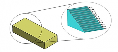
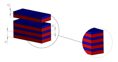
For our experiment, we used a sample consisting of twelve layers (Figure 2) of T300- 3000/Epoxy laminate. Each layer of this laminate consists of 30% epoxy resin and 70% carbon fiber, in line with the usual proportions for this composite material. The fibers in all layers were precisely aligned at 0◦ to the intended orientation, to ensure consistency in the mechanical and structural properties of the sample. We selected this particular configuration for in-depth analysis of the laminate’s performance under real-world conditions, simulating a loading environment where strength and durability play a crucial role.
Figure 2. Constitution of the T300-3000/Epoxy material sample
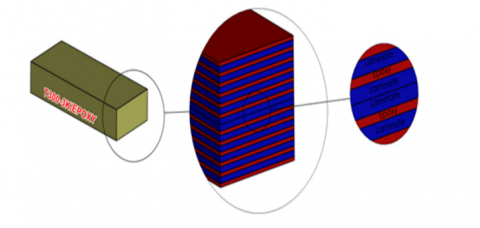
In order to gain a better understanding of the failure mechanisms of composite materials, and to predict more accurately where and when failure may occur, we decided to take a more sophisticated approach to modeling our sample. Initially composed of 12 layers of T300-3000/Epoxy laminate, we chose to replicate it with 24 layers for a more detailed representation (Figure 3).
Figure 3. The new composite sample model
This decision stems from our desire to make significant improvements in our ability to anticipate failures and understand the complex interactions between the different layers making up the laminate.
Although the total thickness of our sample is 2 mm, each individual layer was reduced to a thickness of around 0.167 mm to enable finer resolution in our modeling. However, this more detailed approach presented us with a major challenge: how to accurately and realistically model the interactions between these thin laminate layers. To overcome this challenge, we developed a new modeling approach that incorporates a 0.1 mm thick epoxy interlayer, in addition to the traditional 0.0667 mm thick layer of T300-3000/Epoxy material. This strategy was chosen to allow the epoxy layer to act as a mediator between the actual layers of the laminate, improving our ability to accurately predict fracture behavior and better understand the complex interaction mechanisms within this composite material.
2.2 Influence of advanced theories on delamination studies
Delamination phenomena in laminated composites modeling is emphasized in a variety of mechanical theories. A vital theory of the two is the classical plate theory (CPT) and the higher-order shear deformation theory (HSDT).
The model used in this study is based mainly on classical plate theory (CPT), which assumes that the cross-sections of a plate remain flat and normal to the median surface after deformation. Unfortunately, this assumption does not consider the effect of transverse shear, which causes deviations from predictions of delamination modes, especially for thick laminates.
To understand better the propagation of delamination through multilayer composites, the higher-order shear deformation theory is an alternative that is comparatively more precise. In comparison to classical plate theory, this approach affords:
• Considering non-linear deformations, induced by transverse shear stresses.
• Better modeling interlanar stresses, which directly influence delamination propagation.
• Greater accuracy in assessing critical failure zones, especially in fiber-matrix interfaces.
This work is corroborated by the results, which yield a good correlation between analytical predictions and experimental measurements. However, some discrepancies can be explained utilizig the limitations of the CPT-type model used. Incorporating the HSDT-based approach further in future work will help to make these predictions even better by capturing interlaminar effects and crack propagation more accurately.
Thus, the advanced shear models, together with finite element analysis (FEA), could significantly improve the understanding and modeling of delamination mechanisms in laminated composites.
2.3 The law of behavior of a laminate
The constitutive relationship of laminated composite beams can be formulated as follows [22]:
$
\left\{\begin{array}{c}
\text { Nx } \\
\text { Ny } \\
\text { Nxy } \\
\text { Mx } \\
\text { My } \\
\text { Mxy } \\
\text { Qx } \\
\text { Qy }
\end{array}\right\}=\left[\begin{array}{cccccccc}
\text { A11 } & \text { A12 } & \text { A16 } & \text { B11 } & \text { B12 } & \text { B16 } & 0 & 0 \\
\text { A12 } & \text { A22 } & \text { A26 } & \text { B12 } & \text { B22 } & \text { B26 } & 0 & 0 \\
\text { A16 } & \text { A26 } & \text { A66 } & \text { B16 } & \text { B26 } & \text { B66 } & 0 & 0 \\
\text { B11 } & \text { B12 } & \text { B16 } & \text { D11 } & \text { D12 } & \text { D16 } & 0 & 0 \\
\text { B12 } & \text { B22 } & \text { B26 } & \text { D12 } & \text { D22 } & \text { D26 } & 0 & 0 \\
\text { B16 } & \text { B26 } & \text { B66 } & \text { D16 } & \text { D26 } & \text { D66 } & 0 & 0 \\
0 & 0 & 0 & 0 & 0 & 0 & \text { F44 } & \text { F45 } \\
0 & 0 & 0 & 0 & 0 & 0 & \text { F45 } & \text { F55 }
\end{array}\right\}\left\{\begin{array}{c}
\text { Ex } \\
\text { cy } \\
\text { cxy } \\
\text { kx } \\
\text { ky } \\
\kappa \mathrm{xy} \\
\gamma \mathrm{xz} \\
\gamma \mathrm{yz}
\end{array}\right\} $ (1)
Since the literature mentions that:
$A_{i j}=\sum_{k=1}^n\left(h_k-h_{k-1}\right)\left(\mathrm{Q}^{\prime}{ }_{i j}\right)_k$ (2)
$\mathrm{B}_{i j}=1 / 2 \sum_{k=1}^n\left(h_k^2-h_{k-1}^2\right)\left(\mathrm{Q}^{\prime}{ }_{i j}\right)_k$ (3)
$D_{i j}=\sum_{k=1}^n\left(h_k^3-h_{k-1}^3\right)\left(Q^{\prime}{ }_{i j}\right)_k$ (4)
$F_{i j}=\sum_{k=1}^n\left(h_k-h_{k-1}\right)\left(C^{\prime}{ }_{i j}\right)_k$ (5)
Aij (i, j = 1, 2, 6): The in plane stiffness matrix.
Dij (i, j = 1, 2, 6): The bending stiffness matrix.
Bij (i, j = 1, 2, 6): The bending-extensional coupling stiffness.
Fij (i, j = 4, 5): The transverse shear stiffness.
Mx, My & Mxy: The resulting bending moment.
Nx, Ny & Nxy: The resulting membrane force.
Qx & Qy: The resulting transverse shear force.
If the layers of a composite laminate are symmetrical with respect to a median plane, this enables a significant simplification of the coefficients (Bij) in the material behavior law. This symmetry promotes regularity in the distribution of mechanical properties, reducing the complexity of the calculations and models required to describe the overall behavior of the laminate. Indeed, when layers are symmetrical, shear and bending effects are generally better balanced on either side of the median plane, which simplifies interactions between the different layers. This simplification also makes it easier to interpret experimental results and predict the material’s mechanical performance under a variety of conditions. The symmetry of a composite laminate’s layers thus plays a crucial role in the modeling and analysis of its mechanical behavior.
For our analysis (Figure 4), it is unnecessary to calculate the coefficients of matrix A, which are specific to tensile tests and would be zero in bending tests. Similarly, the coefficients of matrix B, related to shear stresses, are also zero due to the symmetry of the laminate layers with respect to the median plane. We therefore focus solely on the coefficients of matrix D to describe the flexural stiffness properties of the composite material, which is essential for our bending-oriented analysis. This approach allows us to optimize our calculations, avoiding redundancies and obtaining accurate results for our bending study.
Figure 4. A schematic representation of the new model
2.4 Tsai-Hill criterion
The Tsai-Hill criterion, well-supported by scientific research, is valuable for evaluating composite materials due to its consideration of anisotropy, unlike other criteria like Von Mises or Tsai-Wu. It allows assessing of the stress distribution concerning maximum stress in each direction; this is very important for the composite laminated surface with varying fiber orientations. From deformation and damage phenomena associated with composite materials, a proper assessment can be made via this criterion that can take into consideration interaction coefficients and the material's sensitivity towards tension and compression. It is much validated by experiments, bringing extra credibility in predicting the behaviors of composites, help identify zones of stress concentration, and failure, factors regularly in the process of designing safe structures in industries like aerospace. The Tsai-Hill criterion is admired for these highlights: the holistic approach to the anisotropic materials, proper modeling of deformation and fracture behaviors, and predictions backed by verified experimental data.
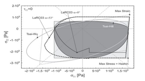
Figure 5. Envelopes of the various shear-free failure criteria in the plane
The graphs in Figure 5 depict the advantages of the different criteria of fracture for composite materials. The Tsai-Hill criterion is exceptional in providing a greater performance compared to the Tsai-Wu criterion, with better prediction and experimental observation agreement. The Tsai-Hill criterion is, however, more serious in compression, which can become problematic for certain applications in engineering. Nevertheless, it remains an important application for the analysis and design of composite materials, chiefly where tensile strength is the focus. Its judicious application has already begun enhancing the performance and safety of composite structures in varying fields. The Tsai-Hill criterion can be used to predict outcomes for unidirectional composite materials using the following Eq. (6) [23].
$\left(\frac{\sigma_L}{X}\right)^2+\left(\frac{\sigma_T}{Y}\right)^2-\left(\frac{\sigma_L \sigma_T}{X^2}\right)+\left(\frac{\sigma_{L T}}{S_{I T}}\right)^2=1$ (6)
σL: is the applied longitudinal stress.
σT: is the applied transverse stress.
X & Y: are the maximum tensile stresses in the longitudinal and transverse directions, respectively.
SLT: is the maximum shear stress.
σLT: represents the maximum shear stress in the material.
In order to apply the Tsai-Hill criterion, it is necessary to compute the response associated with this criterion by every single layer of the composite material. For a particular layer, a below-1 value indicates that the layer can withstand the applied stresses without failing. While a 1.0 value indicates that the layer has reached the strength limit and is likely to dysfunction rather well under the applied levels of load. The analysis allows one to ascertain the overall performance of that particular composite to withstand applied stresses without loss of structural integrity.
The flowchart describes a method of using the Tsai-Hill criterion to check for the failure of individual composite material layers. This begins with defining the materials properties, followed by initializing and loading the required data to compute the bending moment, followed by finding the D matrix and the inverse of this matrix. At this point, coefficients K1, K2 and K3 are also determined. The Tsai-Hill criterion is then calculated for each layer and the result is compared with Tsai-Hill Criterion of 1. If the criterion goes below 1, the process continues without change. If the criterion is equal to or more than 1, that layer is eliminated. The calculation is then repeated for other layers until the Tsai-Hill criterion is satisfied for all layers. Finally, the value that will cause failure for each layer is predicted, thus closing the process.
2.5 Limitations of the Tsai-Hill criterion
Tsai-Hill failure criterion is a model extensively relied upon for measuring the strength of composite materials. Here it has been used to find the beginning of delamination in the laminate layers. It provided good agreement when compared to the experiments, but Tsai-Hill criterion has various limitations, notably in the case of multilayered composites subjected to bending loads.
A major constraint is that the Tsai-Hill criterion is built mainly on an energy approach adapted from isotropic materials which fails to fully capture the anisotropic nature of fiber-reinforced composites. More specifically, normal and shear stress interactions are presumed to follow a quadratic relationship which, in various instances, does not rightly portray real failure mechanisms in laminates subjected to flexural loads.
In addition, due to the fact that the criterion makes no distinction between tensile and compressive failures in the transverse direction, it lacks accuracy for predicting matrix-dominated delamination or interlaminar shear failure. In bending scenarios, where the material experiences opposing tensile and compressive stresses within the laminate thickness, progressive damage models or advanced failure theories such as Tsai-Wu or Hashin's criterion might provide better incorporation of the actual damage evolution.
2.6 Epoxy interface properties
Within the fracture zone, the interface and interaction between the different layers of the composite were represented by a thin layer of epoxy resin, considered to be isotropic. In order to capture the effects of interlaminar interaction, this modeling embodies a simplification of the mechanical behavior of the interface. With this layer, we integrate interlaminar shear stresses and delamination mechanisms, a phenomenon preponderant in the strength, durability and behavior of composite structures. The mechanical properties of this interface are detailed as follows:
Young’s modulus (E): 3.6 GPa
Allowable compressive strength (Xc): 109 MPa
Allowable tensile strength (Xt): 20 MPa
Thickness: e=0.1mm
These attributes have direct impacts on the laminate's response to loading. A stiffer interface enhances stress transfer, while the risk of delamination increases owing to lower elongation at break. An interface that is softer absorbs mechanical loads readily in positively but otherwise may reduce the overall stiffness of the laminate.
The thickness of epoxy interlayer is based on FVF
In this study, the choice of the epoxy interlayer thickness was determined based on the Fiber Volume Fraction (FVF). FVF, defined as the ratio of the fiber volume to the total composite volume (fibers + resin), directly influences the resin distribution between the laminate layers (Figure 6).
The manufacturing process used in this study is an autoclave lay-up, with an assumed FVF of 60%, a typical value found in high-performance composites. Applying the volumetric relation:
$F V F=\frac{V f}{V t}$ (7)
where,
• Vf is the volume occupied by the fibers.
• Vt is the total volume of the composite (fibers + resin).
By applying this ratio, the fiber thickness is calculated to be approximately 0.1 mm, ensuring a realistic distribution within the material. Consequently, the remaining portion of the layer corresponds to the resin, whose thickness is derived by subtracting the fiber thickness from the total layer thickness. This results in a resin thickness of 0.064 mm, which accounts for the interlaminar region essential for stress distribution and delamination resistance.
Figure 6. Epoxy interlayer thickness determined by Fiber Volume Fraction (FVF)
However, to better model interlaminar interactions and ensure a more realistic prediction of delamination, a rounded interlayer thickness of 0.1 mm was selected. This choice ensures a proper balance between stress transfer and delamination resistance, while remaining consistent with experimental practices and literature data.
Similar studies, notably referenced in the study [24] confirm that interlayer thickness values of this order are commonly used to ensure an optimal distribution of interlaminar stresses and to prevent adverse effects associated with excessively thin or thick resin layers. A too-thin interlayer would underestimate interlaminar damage phenomena, while an excessively thick layer could promote the formation of weak resin-rich zones.
Thus, the 0.1 mm thickness selected in our model is justified through a physical, experimental, and bibliographic approach, ensuring a coherent and mechanically accurate representation of laminated composites.
The material T300-3000/Epoxy prepreg is a composite of T300 carbon fibers and type 3000 epoxy resin. T300 carbon fibers are known for their high strength and light weight (Tables 1 and 2), while 3000 epoxy resin offers excellent mechanical properties and high thermal resistance.
Table 1. Mechanical property parameters of T300/epoxy composite [25-28]
|
Property |
Value |
|
Longitudinal modulus, E1 |
115 GPa |
|
Transverse modulos, E2 = E3 |
6.2 Gpa |
|
Shear modulus, G12 = G13 |
4.0 Gpa |
|
Shear modulus, G23 |
3.0 Gpa |
|
Poisson’s ratio, ν12 |
0.31 |
|
Longitudinal tensile strength, Xt |
1800 Mpa |
|
Longitudinal compressive strength, Xc |
855 Mpa |
|
Transverse tensile strength, Yt |
20 Mpa |
|
Transverse compressive strength, Yc |
109 Mpa |
|
Longitudinal shear strength, Sl |
60 Mpa |
|
Transverse shear strength, ST |
40 Mpa |
|
Density, ρ |
1.55 g/cm3 |
|
Thickness of layer, t |
0.1 mm |
|
Longitudinal tensile fracture energy, GCftl |
50.5 N/mm |
|
Longitudinal compressive fracture energy, GCfcl |
30.5 N/mm |
|
Transverse tensile fracture energy, GCftc |
0.368 N/mm |
|
Transverse compressive fracture energy, GCfcc |
1.48 N/mm |
Table 2. 3000 epoxy resin's mechanical property parameters [25-28]
|
Property |
Value |
|
Young’s modulus, E |
3.6 GPa |
|
Shear modulus |
1.33 GPa |
|
Poisson’s ratio, ν |
0.35 GPa |
|
Density, ρ |
1200 kg/m3 |
|
Longitudinal tensile strength, Xt |
80 MPa |
|
Transverse tensile strength, Yt |
110 MPa |
|
Longitudinal shear strength, Sl |
20 MPa |
3.1 Manufacture of T300-3K/Epoxy sample
The method of manufacture of the T300-3000/Epoxy composite material in the autoclave usually comprises several essential steps which should be done in order to obtain the desired quality and properties of the composite material. The first step is to prepare the base materials: T300 carbon fibres and type 3000 epoxy resin are prepared according to the required specifications for the composite. Traditionally, the carbon fibres are pre-impregnated by the resin so as to facilitate their handling and integration into the structure. Then, the layers of carbon fibres and epoxy resin are assembled in accordance with the order and orientation designated in the composite fabrication plan. This process is extremely important for achieving the required mechanical properties: tensile strength and rigidity. Before being transferred to the autoclave, the assembled laminates are frequently vacuum-packed, to create better adhesion between the layers and reduce voids in the final composite. The prepared structure is placed into the autoclave-pressurized chamber capable of providing high temperatures and controlled pressures. The autoclave is required for resin curing and fiber level consolidation. The composite in the autoclave is cured using a controlled curing cycle. Generally, such a cycle would comprise a ramp-up phase for temperature to activate curing the resin and constant temperature-hold phases in order to enable complete polymerization. The cooling down of the completed curing cycle is done in the autoclave without a quick thermal shock that can damage the composite structure. The composite is inspected for quality and performance right after it is taken out of the autoclave after cooling. The recent study reports various enhancements in the fabrication of fiber and epoxy-resin-based composite materials. The use of type T700 carbon fibers can enhance mechanical and thermal properties, showing more suitability for high-performance applications like aerospace and electronic housings. [29, 30].
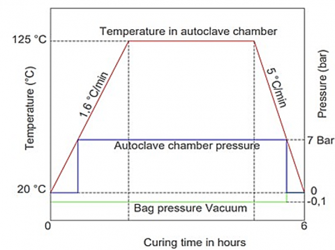
The development of this graph, shown in Figure 6, is for the cure cycle of composite material in an autoclave, with the critical temperature and pressure stages highlighted through six hours. The temperature initially rises at the rate of 1.6℃/min from 20 to 125℃ for 3 hours to ensure complete curing and proper finishing of the epoxy resin. Autoclave pressure is raised to 7 bar, with vacuum bag pressure maintained at -0.1 bar to ease off trapped air and consolidate the lay-up. After the curing phase, the temperature decreases at a rate of 5℃/min back to 20℃, and the pressure is reduced to ambient levels. This curing cycle is intended to assure the best mechanical characteristics for the composite, such that with controlled heating and relatively high-pressure conditions, a void-free, structurally sound material is ensured. This thermal cycle is schematically presented in Figure 7.
Figure 7. The curing cycle of composite materials
3.2 Preparation of the sample
In the course of preparing the samples, the first step was the cutting of the specimens using CNC milling machines. Precision machining assures that the samples comply with good dimensions and specification tolerances. After cutting was done, sample surfaces were polished. Polishing is crucial because it smooths out any irregularities and imperfections of the surface into a high-quality finish. This is of prime importance for future flexural testing because a polished surface allows for better visualization and more accurate reconnaissance of material behavior under stress. Thus, a combination of CNC milling and very fine polishing assured that the test samples were well-prepared for conclusive and sustained testing.
3.3 Point bending test
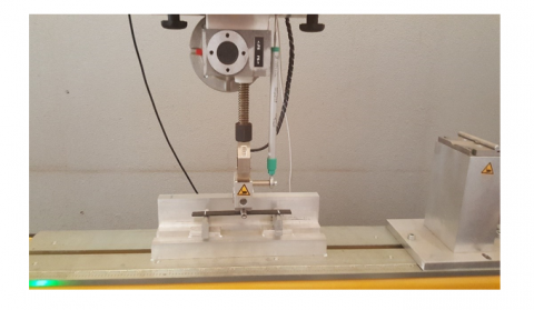
The three-point bending tests per ASTM D790 were conducted to evaluate the structural properties of the composite samples. Tests were conducted using a BED 100 universal testing machine, which was powered with a precision load cell with an accuracy of ±0.5%, thereby ensuring the reliable determination of force [31, 32]. The setup used to perform the test is illustrated in Figure 8. The experimental setup parameters and environmental conditions are as shown in Table 3 and Table 4, respectively.
Figure 8. The 3-point bending test
Table 3. Experimental setup parameters
|
Parameter |
Specification |
|
Testing Machine |
BED 100 Universal Testing Machine |
|
Load Cell Capacity |
10 kN |
|
Span Length (L) |
60 mm |
|
Specimen Dimensions |
100 mm × 20 mm × 2 mm (length × width × thickness) |
|
Support Roller Diameter |
5 mm |
|
Loading Roller Diameter |
5 mm |
|
Crosshead Speed (Load Rate) |
1 mm/min |
|
Data Acquisition Frequency |
50 Hz |
Table 4. Environmental conditions
|
Condition |
Value |
|
Room Temperature |
23℃ ± 2℃ |
|
Relative Humidity |
50% ± 5% |
|
Testing Atmosphere |
Controlled laboratory environment to avoid moisture influence |
The bending test is carried out to determine the mechanical properties of composite materials, including flexural strength, modulus, and strain at final failure. In the bending test, a central load is applied on the support of a beam-shaped specimen at the two points until rupture has occurred or a certain strain is achieved.
Key contributing factors in this regard are sample preparation, loading rate, specimen dimensions, and environmental conditions. Proper sample preparation produces reliable results, as the research [33] emphasized. The loading rate affects flexural behavior, and increasing loading rates will produce an increased apparent strength for a given specimen, as seen in the study [34]. Specimen dimensions, particularly thickness and length, influence outcomes, with thicker specimens exhibiting greater stiffness but complex failure modes [35]. Environmental conditions, such as humidity and temperature, also impact properties, with the study [36] noting decreased flexural strength in humid conditions.
The experimental setup features the BED 100 universal testing machine and a laptop for data acquisition and visualization. The BED 100 applies precise loads and measures deformations with high accuracy. The laptop programs the test conditions and records real-time data, which is later used to plot load-displacement curves.
To verify repeatability and consistency, a minimum of 5 samples were tested for each configuration, and statistical analysis (mean, standard deviation) was performed to assess variability.
4.1 Experimental results
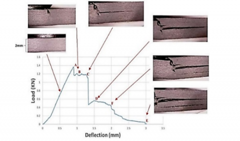
The load-displacement curve showed in the Figure 9 represents the behavior of a composite material sample subjected to a bending test. The key points (A, B, C, D, E, F) marked on the curve correspond to significant events during the test:
Point A (Peak Load): This point represents the maximum load the specimen can withstand before initial failure. The material exhibits its highest strength at this point, with a corresponding maximum load of approximately 1.4 kN and a deflection of around 0.7 mm.
Region B to C (Post-Peak Behavior): After reaching the peak load, the curve shows a slight drop, indicating the initiation of delamination formation within the material. The material still carries a significant load, demonstrating some degree of toughness and resistance to failure.
Point C (Sudden Load Drop): This point denotes a sudden drop in the load, perhaps indicating major failure or crack propagation within the specimen. This sudden drop also indicates brittle failure mode where the material is unable to withstand any load thereafter.
Region D to E (Residual Strength): Following the sharp drop of load, this interval shows a gradual decrease in load-bearing ability with increase in displacement. This reflects the residual strength in materials ex-during deformation. The material still possesses some capacity to sustain load despite having sustained extensive damage.
Point F (Final Failure): The curve continues to decline reflecting some continuous load failure, and finally reaches a stage where it is no longer able to carry significant load. The last point E is regarded as the end of the test where the material has been completely broken down and the load almost reaches a value near zero.
The overall shape of the load-displacement curve provides good insight into the overall mechanical behavior of the composite material under the bending load. The initial linear section is composed of elastic deformation culminating in a peak that indicates the maximum load supportable. The post-peak section speaks about the toughness of the material as well as the capability of sustaining the load despite getting damaged, whereas the descending curve indicates a staged destruction until nothing is left to carry-the load bearing capacity disappears.
Figure 9. The unidirectional sample's macroscopic curve
4.2 Analytical results
Eq. (7) provides the behavior law pertaining to the laminate under study:
$\left\{\begin{array}{c}
0 \\
0 \\
0 \\
0 \\
\mathrm{My} \\
0 \\
0 \\
0
\end{array}\right\}=10^4 *\left[\begin{array}{cccccccc}
0 & 0 & 0 & 0 & 0 & 0 & 0 & 0 \\
0 & 0 & 0 & 0 & 0 & 0 & 0 & 0 \\
0 & 0 & 0 & 0 & 0 & 0 & 0 & 0 \\
0 & 0 & 0 & 4.2490 & 0.1101 & 0 & 0 & 0 \\
0 & 0 & 0 & 0.1101 & 0.3390 & 0 & 0 & 0 \\
0 & 0 & 0 & 0 & 0 & 0.1829 & 0 & 0 \\
0 & 0 & 0 & 0 & 0 & 0 & 0 & 0 \\
0 & 0 & 0 & 0 & 0 & 0 & 0
\end{array}\right\}\left\{\begin{array}{c}
0 \\
0 \\
0 \\
\kappa \mathrm{x} \\
\kappa \mathrm{y} \\
\kappa \mathrm{xy} \\
0 \\
0
\end{array}\right\}$ (8)
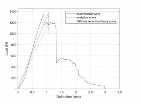
The behavior law together with the Tsai-Hill criterion used in successive approximations allowed us to predict the rupture force value for the first layer of the laminate corresponding to layer N°11: approximately 1383 N (Figure 10). The prediction is made on a basis of a careful analysis of the stress distribution and strength of the composite material. The stress distribution allows modeling of the mechanical response of the laminate under load, while the Tsai-Hill criterion assesses the failure condition by considering all complex interactions between the different layers of the laminate.
Figure 10. Analytical and experimental load-displacement curve
After the determination of layer failure occurred, the model was adjusted, including the damages. The revised behavior law of the laminate accounts for this degradation with the reduction in the number of active layers. Hence, the original model, with 24 layers, was modified into the one having only 22 layers, without the two ruptured layers. This change is important in simulating the post-rupture response of the laminate, whereby the general load-carrying capacity of the material is lowered with the loss of stiffness in the damaged layers.
Thus modified (via Eq. (8)), the model proffers a better representation of the laminate's mechanical behavior under increasing loads, which gives insight into the mechanisms of rupture and delamination. This development also improves prediction capability because these more realistic estimates are able to capture the maximum load the laminate can withstand prior to and after damage initiation. This information is very important for the design and optimization of composite materials within civil applications where either safety or performance is paramount.
$\left\{\begin{array}{c}
0 \\
0 \\
0 \\
0 \\
\mathrm{My} \\
0 \\
0 \\
0
\end{array}\right\}=10^4 *\left[\begin{array}{cccccccc}
0 & 0 & 0 & 0 & 0 & 0 & 0 & 0 \\
0 & 0 & 0 & 0 & 0 & 0 & 0 & 0 \\
0 & 0 & 0 & 0 & 0 & 0 & 0 & 0 \\
0 & 0 & 0 & 4.1988 & 0.0925 & 0 & 0 & 0 \\
0 & 0 & 0 & 0.0925 & 0.2888 & 0 & 0 & 0 \\
0 & 0 & 0 & 0 & 0 & 0.1666 & 0 & 0 \\
0 & 0 & 0 & 0 & 0 & 0 & 0 & 0 \\
0 & 0 & 0 & 0 & 0 & 0 & 0 & 0
\end{array}\right\}\left\{\begin{array}{c}
0 \\
0 \\
0 \\
\kappa \mathrm{x} \\
\kappa \mathrm{y} \\
\kappa \mathrm{y} \\
0 \\
0
\end{array}\right\}$ (9)
4.3 Correlation between experimental and analytical result
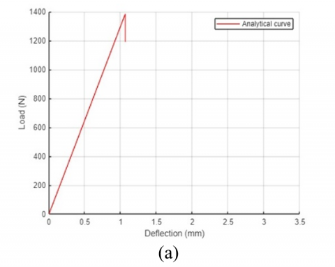
The strong correlation between the corresponding experimental and analytical results affirms our predictive model's effectiveness. It demonstrates less than an 8% difference between either load-displacement curves, emphasizing that the behavior law and Tsai-Hill criterion correctly capture the mechanical responses of the composite material as it was loaded offered by both versions of the framework. The analytical model adequately predicts key events, such as the peak load and the ensuing failure stages, which indicates that its predictions are acceptable. Thus, this close match demonstrates that the model is robust and can surely serve as a valuable tool for predicting composite performance in structural applications where understanding mechanisms of rupture and delamination is critical. The merging of experimental and analytical results provides global confidence about the possible predictive capability of the model in real life. A visual comparison between the experimental and analytical curves is provided in Figure 11.
Figure 11. Comparison between experimental (a) and analytical (b) load-displacement curves
4.4 Comparison between experimental and analytical curves
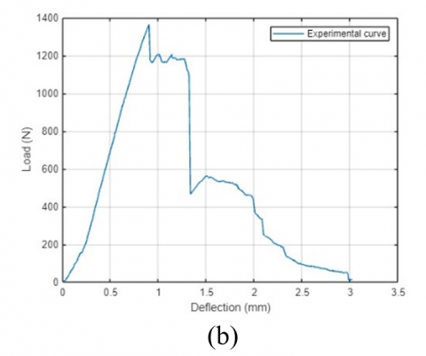
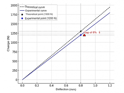
So that the analytical model can be measured against the experimental one, it is compared within the range for which the material exhibits linear-elastic behavior.
Figure 12. Deviation between the experimental and analytical curve
Figure 12 illustrates this comparison for a deflection of 0.8 mm, showing a maximum discrepancy of 8% between the analytically predicted load (1300 N) and the experimentally measured load (1200 N). This deviation might be attributed to other reasons:
In spite of this, the analytical model provides a reasonable approximation of the mechanical response in the elastic regime. However, it appears from Figure 12 that, in higher load, the increasingly diverging response indicates the possibility of obtaining further nonlinear corrections for better accuracy of the model.
4.5 Validation of the analytical model
To validate the analytical model, the predicted values were compared to the data from experimental force-displacement relations obtained from three-point bending experiments. The results indicated a very close agreement between the theoretical model and experimental measurements, thus implying the analytical approach as a reliable predictor for the flexural responses of composite materials.
Nevertheless, after this first point of validation, further concern arises in establishing the robustness of the model. Involvement of cross-validation involving other experimental configurations to assess the generality of the existing model (laminate thickness, fiber orientations, and loading conditions) should be used. Independent experimental datasets or numerical simulations (e.g., finite element analysis-FEA) would also add to the confidence of the model through external validation.
Future studies should focus on validating the analytical model with datasets from different experimental sources like industrial case studies. Also, an FEA simulation with detailed material properties and failure mechanisms is an independent way to cross-verify the predicted performance of the model.
4.6 Practical implications
It is pertinent that the knowledge gained from the study be translated to the confines of the aerospace for performance and durability enhancement of composite materials. T300-3000/Epoxy composites are the most widely used material for aircraft wing construction with some application in fuselage and propulsion parts. The findings of this study enable laminate design to be optimized by incorporating a better understanding of flexural delamination mechanisms. These results can be applied in the following areas:
• Optimization of aeronautical structures: Better choice of lamination sequences to minimize the risk of delamination.
• Improved manufacturing methods: Adjustment of manufacturing parameters and quality controls to limit the occurrence of interlaminar defects.
• Reliability of prediction models: Validation of failure criteria such as Tsai-Hill for the design of new, more resistant composite structures.
• Maintenance and defect detection: Integration of results into delamination detection strategies using ultrasound and other non-destructive methods.
This study paves the way for a more rigorous approach to the design and analysis of composites for aerospace applications. Its integration into industrial processes will significantly improve the reliability and safety of composite structures.
This study investigated the initiation and progression of delamination in carbon/epoxy composite laminates subjected to three-point bending tests. The experimental and analytical results demonstrated a strong correlation, with the analytical model accurately predicting the onset of delamination with a deviation of less than 8% from experimental values.
The analysis revealed that delamination initiation occurs primarily at high interlaminar shear stress zones, particularly near the loading point and the interface between adjacent plies. The progression of delamination was influenced by fiber orientation, epoxy layer thickness, and loading conditions, with specimens exhibiting rapid crack propagation once a critical stress threshold was exceeded.
The validation of the Tsai-Hill failure criterion has justified its reliability in predicting delamination under bending loads although some limitations, with emphasis on the inability to differentiate tensile from compressive failures in the transverse directions were observed. Future work should account for HSDT and progressive damage models for higher-delamination prediction accuracies.
The results of this investigation have direct implications for the design and testing of aerospace composite structures. The understanding of delamination mechanisms under flexure loading can allow engineers to develop composite laminates that are more damage tolerant, optimize fiber lay-up configurations, and improve non-destructive techniques to effectively identify structural defects. Further validation via finite element analysis (FEA) and experimental tests on aerospace-grade composite laminates is recommended to increase the predictive capability of the analytical model.
This research received financial support from the National Center for Scientific and Technical Research (CNRST), Morocco.
[1] Cui, J., Luo, H., Wang, R., Zhang, J., Chen, J., Ba, Z., Ma, C. (2024). Damage identification and fracture behavior of 2.5 D SiCf/SiC composites under coupled stress states. Materials & Design, 241: 112964. https://doi.org/10.1016/j.matdes.2024.112964
[2] Zhao, J., Wang, Y., Wu, H., Ruan, M. (2021). Coupling mechanism of highly nonlinear solitary waves with damaged composite material plates. Composites and Advanced Materials, 30: 1-10. https://doi.org/10.1177/2633366X20928088
[3] Fatima, K., Bachir, E., Fabienne, D. (2019). Review of damages prediction in a composite material at low velocity impact. Global Journal of Engineering and Technology Advances, 1(1): 27-42. https://doi.org/10.30574/gjeta.2019.1.1.0007
[4] Neto, A., Santos, S., Alves, M.L. (2024). Numerical evaluation of damage in laminated composite tubes under low-speed impacts. Procedia Structural Integrity, 53: 338-351. https://doi.org/10.1016/j.prostr.2024.01.041
[5] Ghobadi, A. (2017). Common type of damages in composites and their inspections. World Journal of Mechanics, 7(2): 24-33. https://doi.org/10.4236/wjm.2017.72003
[6] Li, Y., Qin, H., Tan, V.B.C., Jia, L., Liu, Y. (2024). A deep transfer learning approach to construct the allowable load space of notched composite laminates. Composites Science and Technology, 247: 110432. https://doi.org/10.1016/j.compscitech.2024.110432
[7] Cui, J., Luo, H., Wang, R., Zhang, J., Chen, J., Ba, Z., Ma, C. (2024). Damage identification and fracture behavior of 2.5 D SiCf/SiC composites under coupled stress states. Materials & Design, 241: 112964. https://doi.org/10.1016/j.matdes.2024.112964
[8] Wang, Q., Qin, H., Jia, L., Li, Z., Zhang, G., Li, Y., Liu, Y. (2024). Failure prediction and optimization for composite pressure vessel combining FEM simulation and machine learning approach. Composite Structures, 337: 118099. https://doi.org/10.1016/j.compstruct.2024.118099
[9] Hashin, Z. (1980). Failure criteria for unidirectional fiber composites. Journal of Applied Mechanics. 47(2): 329-334. https://doi.org/10.1115/1.3153664
[10] Bai, J.B., You, F.Y., Wang, Z.Z., Fantuzzi, N., Liu, Q., Xi, H.T., Liu, T.W. (2024). An efficient multi-objective optimization framework for thin-walled tubular deployable composite boom. Composite Structures, 327: 117713. https://doi.org/10.1016/j.compstruct.2023.117713
[11] Esmaeili, A., Mohammadi, B., Yousefi, A. (2024). Investigation of T-stress and tensile strength effect on crack tip conditions and crack initiation angle in off-axis laminate composite. Theoretical and Applied Fracture Mechanics, 130: 104283. https://doi.org/10.1016/j.tafmec.2024.104283
[12] Maguire, J.M., Mamalis, D., Ōtomo, S., McCarthy, E.D. (2024). Passively morphing trailing edge design for composite tidal turbine blades. Composite Structures, 337: 118090. https://doi.org/10.1016/j.compstruct.2024.118090
[13] Kovács, L., Bugár-Mészáros, M., Romhány, G. (2024). Holistic estimation and sensitivity-based experiment design method of composite laminate first-ply failure models using statistical approaches. Engineering Failure Analysis, 156: 107834. https://doi.org/10.1016/j.engfailanal.2023.107834
[14] Bai, J.B., You, F.Y., Wang, Z.Z., Fantuzzi, N., Liu, Q., Xi, H.T., Liu, T.W. (2024). An efficient multi-objective optimization framework for thin-walled tubular deployable composite boom. Composite Structures, 327: 117713. https://doi.org/10.1016/j.compstruct.2023.117713
[15] Nali, P., Carrera, E. (2012). A numerical assessment on two-dimensional failure criteria for composite layered structures. Composites Part B: Engineering, 43(2): 280-289. https://doi.org/10.1016/j.compositesb.2011.06.018
[16] Montemurro, M., Roiné, T. (2024). Strength-based topology optimisation of anisotropic continua in a CAD-compatible framework. Advances in Engineering Software, 189: 103591. https://doi.org/10.1016/j.advengsoft.2023.103591
[17] Pisani, W. A., Radue, M.S., Patil, S.U., Odegard, G.M. (2021). Interfacial modeling of flattened CNT composites with cyanate ester and PEEK polymers. Composites Part B: Engineering, 211: 108672. https://doi.org/10.1016/j.compositesb.2021.108672
[18] Catalanotti, G., Camanho, P.P., Marques, A.T. (2013). Three-dimensional failure criteria for fiber-reinforced laminates. Composite Structures, 95: 63-79. https://doi.org/10.1016/j.compstruct.2012.07.016
[19] Karamanli, A., Vo, T.P., Eltaher, M.A. (2024). Comprehensive analysis of bio-inspired laminated composites plates using a quasi-3D theory and higher order FE models. Thin-Walled Structures, 198: 111735. https://doi.org/10.1016/j.tws.2024.111735
[20] Liu, S., Che, L., Fang, G., Liang, J. (2024). A conjugated bond-based peridynamic model for laminated composite materials. International Journal of Mechanical Sciences, 265: 108893. https://doi.org/10.1016/j.ijmecsci.2023.108893
[21] Reddy, J.N. (2003). Mechanics of Laminated Composite Plates and Shells: Theory and analysis. CRC press.
[22] Auricchio, F., Sacco, E. (2003). Refined first-order shear deformation theory models for composite laminates. Journal of Applied Mechanics, 70(3): 381-390. https://doi.org/10.1115/1.1572901
[23] Tsai, S.W.W., Hahn, H.T. (1980). Introduction to Composite Materials. Technomic Publishing, Lancaster. pp. 377-431.
[24] Sun, C.T., Tao, Z. (1990). Delamination of laminated composites due to matrix cracking. Composite Structures, 14(4): 317-337. https://doi.org/10.1016/0263-8223(90)90112-E
[25] Zhu, G., Sun, G., Li, G., Cheng, A., Li, Q. (2018). Modeling for CFRP structures subjected to quasi-static crushing. Composite Structures, 184: 41-55. https://doi.org/10.1016/j.compstruct.2017.09.001
[26] Zhu, X., Xiong, C., Yin, J., Zhou, H., Zou, Y., Fan, Z., Deng, H. (2023). Experimental study and modeling analysis of planar compression of composite corrugated, lattice and honeycomb sandwich plates. Composite Structures, 308: 116690. https://doi.org/10.1016/j.compstruct.2023.116690
[27] Zhu, X., Zheng, J., Xiong, C., Yin, J., Deng, H., Zou, Y., Song, S. (2021). Compression responses of composite corrugated sandwich square tube: Experimental and numerical investigation. Thin-Walled Structures, 169: 108440. https://doi.org/10.1016/j.tws.2021.108440
[28] Liao, B., Jia, L., Zhou, J., Lei, H., Gao, R., Lin, Y., Fang, D. (2020). An explicit–implicit combined model for predicting residual strength of composite cylinders subjected to low velocity impact. Composite Structures, 247: 112450. https://doi.org/10.1016/j.compstruct.2020.112450
[29] Wang, H., Zhang, L. (2019). Pyrolysis and combustion characteristics and reaction kinetics of carbon fiber/epoxy composites. AIP Advances, 9(12): https://doi.org/10.1063/1.5128460
[30] Martins, M., Gomes, R., Pina, L., Pereira, C., Reichmann, O., Teti, D., Rocha, N. (2018). Highly conductive carbon fiber-reinforced polymer composite electronic box: Out-of-autoclave manufacturing for space applications. Fibers, 6(4): 92. https://doi.org/10.3390/fib6040092
[31] Chai, H., Nutt, S. R. (2001). Evaluation of the flexural strength of sandwich composites. Composites Science and Technology, 61(13): 2029-2041. https://doi.org/10.1016/S0266-3538(01)00113-5
[32] Kim, H.S., Kim, J.H., Kim, C.G. (2004). Evaluation of flexural strength of carbon fiber-reinforced epoxy composites with high-modulus fibers. Composites Part B: Engineering, 35(6-8): 559-566. https://doi.org/10.1016/j.compositesb.2004.02.003
[33] Liu, D., Wang, Y., Li, S., Zhang, H. (2020). Multiscale modeling of mechanical behavior of fiber-reinforced polymer composites: A review. Composite Structures, 236: 111920. https://doi.org/10.1016/j.compstruct.2019.111920
[34] Furtado, C., Marques, A., de Moura, M., Morais, J. (2018). Advanced analysis of composite laminates using 3D solid finite elements: A review. Composite Structures, 184: 704-722. https://doi.org/10.1016/j.compstruct.2017.10.022
[35] Goh, G.D., Yap, Y.L., Tan, H.K.J., Sing, S.L., Goh, G.L., Yeong, W.Y. (2020). Process–structure–properties in polymer additive manufacturing via material extrusion: A review. Critical Reviews in Solid State and Materials Sciences, 45(2): 113-133. https://doi.org/10.1080/10408436.2018.1549977
[36] Neto, J., Queiroz, H., Aguiar, R., Lima, R., Cavalcanti, D., Banea, M.D. (2022). A review of recent advances in hybrid natural fiber reinforced polymer composites. Journal of Renewable Materials, 10(3): 561-589. https://doi.org/10.32604/jrm.2022.017434