Thermomechanical Analysis of a Gas Turbine Blade in Composite Materials with a Ceramic (Al2O3) Coated

Abd El Halim Ferrak*![]() | Rabah Manaa | Khalid Faiza
| Rabah Manaa | Khalid Faiza![]()
© 2024 The authors. This article is published by IIETA and is licensed under the CC BY 4.0 license (http://creativecommons.org/licenses/by/4.0/).
OPEN ACCESS
The efficiency of modern turbomachinery is presently limited by the strength of the blade material, as the upper part of the body of the blade is subjected to different types of loads such as traction, bending forces high, centrifugal forces, corrosion, oxidation, breakage, pressure and high temperature. Improving blade durability is the main goal of the making them capable of withstanding harsh conditions. This paper focuses on the modeling and analysis numerical of turbine blades, who is fabricated with different materials Alloy in coated and uncoated or who is fabricated with the ceramic (Al2O3). Three dimensional model real of the blade is modeled and analysis with a numerical method using the components C.A.O and Analysis of software SOLIDWORKS. This study specifies the analysis of an intricate turbine blade geometry and application of boundary conditions to test the steady-state thermal performance of the blades in composite material reinforced with mast which is coated by ceramic matrix composites and uncoated turbine blade to other materials alloys such as Titanium, Stainless Steel, Aluminum2024, composite material, Inconel 718 and Haynes 188. Finally stating the most excellent suited material among them. From our results analysis and simulation for all materials coated and uncoated.
coated blade, uncoated blade, alumina, high modulus carbon, thermos-mechanical behavior, finite element model, mast, Al2O3
Turbomachines occupy an important place because they are used in almost all industrial fields where there is an exchange of power by rotation in the production of electrical energy. The gas turbines are a fundamental importance in modern engineering applications. They are the principal components used for generating electrical energy. They present today diversity and richness of a notable design. The life of gas turbine components is obeyed by degradation and failure modes such as fatigue, creep, corrosion, erosion, wear, etc. A turbine blade is the fundamental component that composes the turbine section of a gas turbine engine. Blades serve to extract energy from the high-pressure gases produced by the compressor. To withstand at this harsh environment, turbine blades were manufactured with special materials such as the super alloys and often use various cooling methods such as internal air ducts, boundary superficial layer cooling with thermal barrier coatings. The primary reason for turbine failure is blade fatigue. She is caused by temperature, vibration stress, resonance in the operating range. The objective of this work is to compare between the blade materials with ceramic coating and uncoated. This is done by simulating the real conditions of turbine blade operation in SolidWorks software. According to the study, coated composite material performance is better than other alloys in all aspects such as displacements and strains. And select the most suitable blade material for gas turbines, as existing alloys generate more heat during operation, leading to oxidation and hot corrosion, thermal fatigue. And to overcome these causes, ceramic (alumina) can be used as coating media.
Numerous researchers have studied the thermal and mechanical analysis of turbine blades in order to optimize the performance of materials. Faiza et al. [1] conducted structural and thermomechanical analysis of the blade using the software ANSYS. The strains and displacements were determined using different materials: composite material reinforced with carbon fibers, Aluminum2024, Stainless Steel, and Titanium. Zhu et al. [2] developed a three-dimensional finite element model of a blade coated with a multilayer structure, where heat transfer analysis and thermal-stress calculation methods are decoupled and adopted. To get closer to the real temperature field, Vishnu et al. [3] studied thermal barrier coatings (TBC), applying a PSZ barrier coating on a turbine blade and optimizing its thickness for the best performance in the critical environments inside a gas turbine. Li et al. [4] developed a method for designing the TBC thickness apportionment for the turbine blade. They built and analyzed 3D finite element models using this approach. Criffin and Kumar [5] used ANSYS software to design and analyze the steady-state thermal performance of a blade coated with SiC/SiC to determine the best-suited material. Wen et al. [6] developed effusive cooling schemes for gas turbine blades, emphasizing the flow and heat transfer mechanisms and revealing the design trends of these cooling schemes. Akshay et al. [7] reviewed common failures due to metallurgical defects found in gas turbines, discussing external and internal surface damages such as corrosion, oxidation, crack formation, erosion, and foreign object damage. Meisner and Elizabeth [8] performed thermo-chemical calculations using Fact Sage for gas turbine environments, using the results to explain variations in deposit chemistry. Kumar et al. [9] conducted thermo-mechanical analysis of a typical SGT engine to study the blade tip clearance influenced by the deformation of turbine stage components, using ANSYS Workbench for transient thermal and structural analyses, considering temperature-dependent material properties and a speed of 45,000 rpm. Mossef and Venkadesh [10] discussed the use of adhesive material to assemble large composite structures, noting that structural adhesives are specifically formulated to join high-strength composite materials. Jabbar et al. [11] performed structural, modal, and thermal analyses on the apportionment of thermal stress, pressure, mechanical stress, and temperature of the blade using different materials such as Stainless Steel alloy, Titanium alloy, and Aluminum 2024 alloy. Sadowski et al. [12] solved the transient temperature transfer problem in bare and thermal barrier-coated Inconel 713 alloys for temperatures up to 1000℃, performing fluid dynamics analysis using ANSYS. Theju et al. [13] designed and evaluated the stress and temperature influence on a jet engine turbine blade using novel materials: Inconel 718 and Titanium T6. Cao et al. [14] modified the characteristics of ZrO₂-based ceramics. Ogirikia and Li [15] developed an estimation model capable of predicting the impact of different forms of degradation on the creep life of turbine blades. Vaßen et al. [16] provided an overview of new materials, especially zirconia. Shina et al. [17] conducted tests on coated samples to evaluate the properties of TBC. Zhu et al. [18] worked on developing and predicting the life of erosion-resistant turbine blades with low-conductivity thermal barrier coatings. Padture et al. [19] carried out research on new thermal barrier coatings for gas turbine blades.
3.1 Materials properties
Material selection criteria aim to increase operating resistance in harsh environments such as fatigue, high temperature and pressure, oxidation, vibration stresses, and resonance.
a. Composite material: The matrix is manufactured from aluminum oxide (Al₂O₃) with high modulus carbon short fibers as reinforcement, as given by Gay [20]. These materials have the ability to withstand very high temperatures and high mechanical loads to deliver high performance. The thermal characteristics are explained by Mallick [21], and the mechanical properties of the composite material are taken from [22] (Table 1).
b. Aluminum2024 alloy: This is a heat-treatable alloy with copper as the primary alloying element. It can achieve high strength levels after forming. The mechanical properties are taken from [1] (Table 1).
c. Stainless Steel alloy: Known as stainless steel, this iron alloy is composed of iron, chromium, and nickel. It does not rust in water and is resistant to concentrated acids. The mechanical properties are taken from [1] (Table 1).
d. Inconel 718: This alloy contains iron, niobium, and molybdenum, with lesser amounts of aluminum and titanium. It has excellent creep rupture strength at temperatures up to 700°C. The mechanical properties are taken from [2] (Table 1).
e. Titanium alloy: Used in the aviation industry, this alloy has the highest strength, impact toughness, and corrosion resistance. Its mechanical properties are taken from [1] (Table 1).
f. Haynes 188: This is a cobalt-based alloy with excellent oxidation strength at high temperatures up to 1100°C. It has good resistance to sulfidation, good metallurgical stability, and can be easily fabricated. Its mechanical properties are taken from [2] (Table 1).
Table 1. Mechanical property of the different blade materials [14]
|
Materials |
Titanium Alloy |
Stainless Steel Alloy |
Aluminum2024 Alloy |
Composite Material |
Inconel 718 |
Haynes 188 |
|
Density [Kg/m3] |
4700 |
8025 |
2750 |
2940 |
8300 |
8980 |
|
Young’s modulus [GPa] |
205 |
200 |
73 |
400.44 |
200 |
232 |
|
Poisson’s ratio |
0.33 |
0.3 |
0.33 |
0.2797 |
0.29 |
0.325 |
|
Yield strength [MPa] |
1000 |
1050 |
470 |
1840 |
1240 |
946 |
|
Coefficient of thermal expansion 10-6℃ |
8.8 |
14.5 |
23.3 |
5.075 |
16 |
16.9 |
3.2 CAD modeling
Three dimensional model of blade made with software SOLIDWORKS which is presented and show in Figure 1.
Figure 1. CAD model
Finite element analysis was used for the determination of strain and displacement of the turbine blade using different materials coated and uncoated under the same operating conditions.
Tetrahedron elements (Tet4) it is the shape simplest to mesh a three dimensional geometric model. It is adapted for automatic mesh generation; such is composed of 61844 elements and 105015 nodes, respectively, as show in Figure 2.
Figure 2. Meshed model of the blade
The model was created and analyzed using SolidWorks software with the specified load and boundary conditions. The results of the study are detailed in the following discussions.
5.1 Static analysis of blade
Structural analysis using a finite elements model for the turbine blade involves assessing the impact of steady loading conditions on a structure. The strain and displacement values of the blade were determined through numerical analysis using SOLIDWORKS software.
5.2 Boundary condition
The Half of the blade root is fixed in the rotor of gas turbine Figure 3, so the displacement boundary conditions applied to the half of the blade root are Ux = Uy = Uz = 0, and the rotations of all the nodes are constrained, Rx = Ry= Rz = 0.
Figure 3. Boundary condition and loading on the blade
5.3 Loading on the Blade
Three types of loads subjected on the turbine blade, Axial force Fa = 3.82 N, Tangential force Ft = 248.199 N, Centrifugal force Fc = 38038.73 N. They are applying to the node located at blade centroid.
We compared our results with those obtained by [1] to confirm the reliability of this study. This comparison was conducted on the following materials: Aluminum2024 alloy, Stainless Steel alloy, Titanium alloy, and Composite material. In this section on validation Figures 4-7 show the maximum displacement blade in the different materials.
Figure 4. Resultant displacements of Titanium alloy blade, with a maximum magnitude of 1.026mm
Figure 5. Resultant displacements of Stainless Steel alloy blade, with a maximum magnitude of 1.604mm
Figure 6. Resultant displacements of Aluminum2024 alloy blade, with a maximum magnitude of 2.749mm
Figure 7. Resultant displacements of composite material blade, with a maximum magnitude of 0.580mm
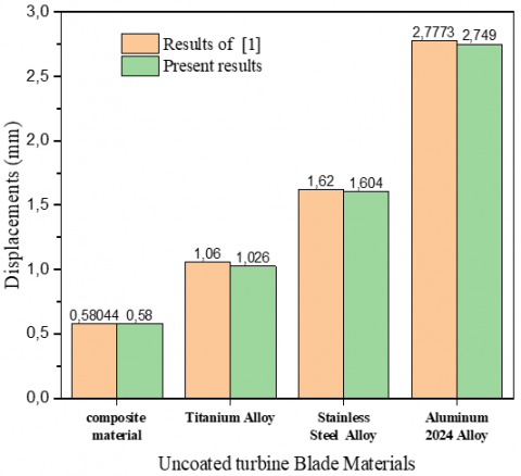
Figure 8. Uncoated blade materials as function of displacements
Figure 8 shows and indicates displacement results as a function of the uncoated blade Materials. These results indicate the comparison and the conformity between our numerical study and the one of Faiza et al. [1]. We noted that precision of our numerical analysis study gives acceptable results comparable with the one of Faiza et al. [1].
Table 2. Comparing the displacements results of our study with previous results
|
Materials |
Previous Results [1] |
Present Results |
$\Delta \mathbf{U}$ |
|
Composite material |
0.58044 |
0.580 |
-0.075% |
|
Titanium Alloy |
1.06 |
1.026 |
-3.207% |
|
Stainless Steel |
1.62 |
1.604 |
-0.987% |
|
Aluminum2024 Alloy |
2.7773 |
2.749 |
-1.018% |
Table 2 indicates the comparison between our numerical study and the one of Faiza et al. [1]. And the difference $\Delta \mathbf{U}$ between all displacements, where we noticed precision of our numerical analysis study gives acceptable results comparable. The minimum displacement error value $\Delta \mathbf{U}$ is found in composite material which at -0.075%, while the maximum displacement in the Titanium alloy with a magnitude of is -3.207%.
In this part of the study, we analyze the thermomechanical behavior of the blade. We present the results of strains and displacements for both uncoated and coated turbine blades under the same loading and boundary conditions as previously defined, considering the influence of the temperature (T=800℃).
7.1 Analysis of uncoated turbine blade
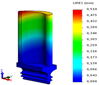
Figures 9-12 show the results of strains and displacements of uncoated turbine blade in the different materials. We observed the maximum displacement occurs at the upper blade part turbine blade (tip) and minimum value occurs at the lower blade part (root). As well as the maximum strain occurs at the lower blade part (root) and minimum value occurs at the upper blade part turbine blade (tip).
Figures 13-14 show the evolution of strains and the displacements as a function of the uncoated turbine blade height, so it can observe as following:
Strain and displacement of blade with composite material are the better results in comparison with the other materials.
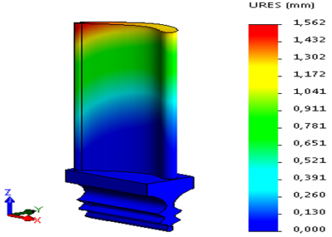
Figure 9. Resultant displacements of Inconel 718 blade, with a maximum magnitude of 1.562mm
Figure 10. Distribution strains of Inconel 718 blade, with a maximum magnitude of 0.007544
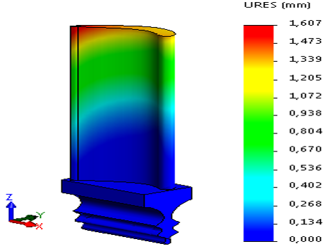
Figure 11. Resultant displacements of Haynes 188 blade, with a maximum magnitude of 1.607mm
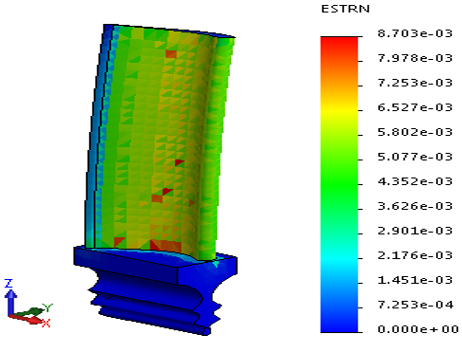
Figure 12. Distribution strains of Haynes 188 blade, with a maximum magnitude of 0.008703
Figure 13. Comparing displacements for uncoated materials blade
Figure 14. Comparing strains for uncoated materials blade
The minimum displacement value is found in composite material blade which at 0.580mm, while the maximum displacement in the Aluminum2024 alloy with a magnitude of is 2.749mm.
The minimum strain value is found in composite material blade which at 0.002307. While the maximum strains are in the Aluminum2024 alloy with at 0.01384
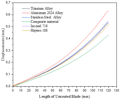
Figure 15 illustrates the comparison between displacement results for different uncoated turbine blade.
We noted that displacements vary in function the increase in the radial distance. And that maximum value of displacements of the blade in the Aluminum2024 alloy, as well as the minimum value occurs in the composite of our study.
Figure 15. Uncoated blade materials according to displacements
7.2 Analysis of coated turbine blade
Figures 16-19 show the strain and the displacement of coated turbine blade in different materials.
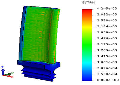
We observed the maximum displacement occurs at the upper blade part turbine blade (tip) and the minimum value occurs at the lower blade part (root). As well as the maximum strain occurs at the lower blade part (root) and the minimum value occurs at the upper blade part turbine blade (tip).
Figures 20 and 21 show the evolution of strains and displacements as a function of the coated turbine blade height so it can observe as following:
The strain and displacement of blade with composite material gives better results in comparison with other materials.
Figure 16. Resultant displacements of Inconel 718 blade, with a maximum magnitude of 0.544
Figure 17. Distribution strains of Inconel 718 blade, with a maximum magnitude of 0.004192
Figure 18. Resultant displacements of Haynes 188 blade, with a maximum magnitude of 0.519
Figure 19. Distribution strains of Haynes 188 blade, with a maximum magnitude of 0.004245
Figure 20. Comparing displacements for coated materials blade
Figure 21. Comparing Strains for coated materials blade
The minimum displacement value is found in composite material blade which at 0.429mm, while the maximum displacement in the Aluminum2024 alloy with a magnitude of is 0.633mm. The minimum strain value is found in composite material blade which at 0.00150. While the maximum strains are in the Aluminum2024 alloy with at 0.005238.
Figure 22 illustrates the comparison between displacement results for different coated turbine blade. It notes that displacements vary with the increase in the radial distance. And it indicated that maximum value of the displacements is in the Aluminum2024 alloy and minimum value occurs in the composite material of our study.
Figure 22. Coated blade materials according to displacements
7.3 Compared of obtained results
In this case, we compare the results study of the thermos-mechanical and determine the strains and the displacements among uncoated and coated blade under a same loading condition and a boundary previously defined.
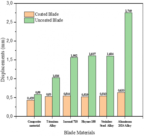
Figure 23 shows displacements in function of blade materials. It can be observed that displacement of coated blade is better results in comparison with uncoated blade.
Note that displacements vary with radial distance increases; We notice that maximum value is for the Aluminum2024 alloy and minimum value of the composite material, either for coated or uncoated blade. Due to the impacts of stagnation, the leading edge of the blade is uncovered to the greatest temperatures.
The body temperature of the blade doesn’t change much within the radial direction. However; there is a temperature fall from the leading to the trailing edge of the blade. Blade with coated shows superior dissipation exhibits of heat compared to the uncoated alloy.
Figure 23. Comparing displacements for uncoated blade and coated blade for all materials
The coated composite material creates less heat compared to other coated alloys so it’s prescribed for higher thermal operating conditions.
Table 3. Results of study analysis thermos-mechanical for uncoated blade and coated blade for all materials
|
Materials |
Displacements (mm) |
$\Delta \mathbf{U}$ |
|
|
Coated Blade |
Uncoated Blade |
||
|
Composite Material |
0.429 |
0.580 |
-26.034% |
|
Titanium Alloy |
0.530 |
1.026 |
-48.343% |
|
Inconel 718 |
0.544 |
1.562 |
-65.172 |
|
Haynes 188 |
0.519 |
1.607 |
-67.703 |
|
Stainless Steel Alloy |
0.543 |
1.604 |
-66.957 |
|
Aluminum2024 Alloy |
0.633 |
2.749 |
-76.973 |
Table 3 indicates us the comparison between coated and uncoated blade. And the difference $\Delta \mathbf{U}$ between all displacements, where we noticed precision of our numerical analysis study gives acceptable results comparable. The minimum displacement error value $\Delta \mathbf{U}$ is found in composite material which at -26.034%, while the maximum displacement in the Aluminum2024 alloy with a magnitude of is -76.973. We noticed the excellent effect of the aluminum coating on the displacements in the higher thermal operating conditions.
- According to the study, all materials giving the considerable results.
- The extremely high temperature, pressure, and oxidation have a significant effect on the strains and displacements on the turbine blade.
- We observed maximum displacements at the upper part of the turbine blade (tip) and minimum displacement at the lower part (root). The deformations gradually increase from the lower part (root) to the upper part (tip) of the blade. The performance of coated composite materials is better than other alloys in all aspects, including displacements and strains.
- By choosing an optimized composite material, deformation along the blade is significantly reduced, which reduces localized micro-cracks that lead to wear. The study includes the development of a methodology to achieve the desired outcome.
1. An important study of the thermomechanical behavior related to the wear of turbine blades (problems) of various materials.
2. A comprehensive literature review of new composite materials and the technical means of incorporating them into turbine blade design and manufacturing. After an optimization study, we selected the optimal composition. The choice of reinforcement/matrix is carbon/ceramic, and the coated blade is alumina (Al₂O₃).
3. A continuous study of simulations performed on real geometric models (blades) made of composite materials to define the displacement and local deformation of identical points in different materials. We compared these with the same models made of superalloys.
4. A simulation study carried out on a real geometric model with an uncoated blade using the simulation component of the software SOLIDWORKS.
5. A simulation study carried out on a real geometric model with a coated blade using the simulation component of the software SOLIDWORKS.
6. We compared the numerical analysis results obtained using uncoated and coated turbine blades, simulated with SOLIDWORKS software.
7. The results showed a significant increase in fin stiffness and a reduction in blade tip displacement, reducing local deformation. These results lead to the conclusion that sediment-induced crack formation is significantly reduced.
8. The optimization of composites (carbon/ceramic) with ceramic coatings in turbojet blade designs confirmed that this combination is well suited for optimal thermomechanical behavior. Improvements include increased rigidity, reduced local deformation, reduced micro-cracks, elimination of carbon oxidation due to the heat shielding effect, adoption of ceramic (alumina) for coating, and extended lifespan.
[1] Faiza, K., Manaa, R., Saad, S., Ameddah, H. (2021). A study of thermo-mechanical behavior of a gas turbine blade in composite materials reinforced with Mast. Journal of Composite and Advanced Materials, 31(2): 101-108. https://doi.org/10.18280/rcma.310205
[2] Zhu, W., Wang, J.W., Yang, L., Zhou, Y.C., Wei, Y.G., Wu, R.T. (2017). Modeling and simulation of the temperature and stress fields in a 3D turbine blade coated with thermal barrier coatings. Surface and Coatings Technology, 315: 443-453. https://doi.org/10.1016/j.surfcoat.2017.03.012
[3] Vishnu, S., Ramkumar, P.B., Deepak, S., Doyel, J., Jithu, J., Abraham, K. (2019). Optimized thermal barrier coating for gas turbine blades. Materials Today, 11: 912-919. https://doi.org/10.1016/j.matpr.2018.12.018
[4] Li, B., Fan, X., Li, D., Jiang, P. (2017). Design of thermal barrier coatings thickness for gas turbine blade based on finite element analysis. Mathematical Problems in Engineering, 2017(2147830): 13. https://doi.org/10.1155/2017/2147830
[5] Griffin, T., Kumar, B.R. (2017). Analysis of ceramic (SiC) coated gas turbine blade using ANSYS. ResearchGate, 2: 30-45. https://www.researchgate.net/publication/335259150
[6] Wang, W., Yan, Y., Zhou, Y.Q., Cui, J.H. (2022). Review of advanced effusive cooling for gas turbine blades. Energies, 15(22): 8568. https://doi.org/10.3390/en15228568
[7] Akshay, U., Pawan, N., Pratik, G., Tushar, D. (2022). A review on failure analysis of turbine blades of aero gas turbine engine. International Journal of Scientific Research in Science and Technology, 187-192. https://doi.org/10.32628/IJSRST229335
[8] Meisner, K.J., Elizabeth, J. (2020). Hot corrosion of shipboard gas turbine blades. Oxidation of Metals, 94(3): 301-322. https://doi.org/10.1007/s11085-020-09990-7
[9] Kumar, R., Kumar, V.S., Butt, M.M., Sheikh, N.A., Khan, S.A., Afzal, A. (2020). Thermo-mechanical analysis and estimation of turbine blade tip clearance of a small gas turbine engine under transient operating conditions. Applied Thermal Engineering, 179: 115700. https://doi.org/10.1016/j.applthermaleng.2020.115700
[10] Mossef, D.-H., Venkadesh, R. (2016). Macro and meso-scale study in composite lay-up orientation effect on adhesive material used in wind turbine blades. Journal of Composite and Advanced Materials, 26(1): 25-44. https://doi.org/10.3166/RCMA.26.25-44
[11] Jabbar, A.A., Rai, A.K., Reedy, P.R., Dakhil, M.H. (2014). Design and analysis of gas turbine rotor blade using finite element method. International Journal of Mechanical and Production, 4(1): 91-112. https://www.researchgate.net/publication/274373167
[12] Sadowski, T., Golewski, P. (2011). Multidisciplinary analysis of the operational temperature increase of turbine blades in combustion engines by application of the ceramic thermal barrier coatings (TBC). Elsevier Computational Materials Science, 50(1): 1326-1335. https://doi.org/10.1016/j.commatsci.2010.05.032
[13] Theju, V., Uday, P.S., Reddy, P.L.V.G., Manjunath, C.J. (2014). Design and analysis of gas turbine blade. International Journal of Innovative Research in Science, Engineering and Technology, 3(6): 13533-13539. https://doi.org/10.17148/IARJSET.2022.9606
[14] Cao, X.Q., Vassen, R., Stoever, D. (2004). Ceramic materials for thermal barrier coatings. Journal of the European Ceramic Society, 24(1): 1-10. https://doi.org/10.1016/S0955-2219(03)00129-8
[15] Ogirikia, E.A., Li, Y.G. (2015). Effect of fouling, thermal barrier coating degradation and film cooling holes blockage on gas turbine engine creep life. Procedia CIRP, 38: 228-233. https://doi.org/10.1016/j.procir.2015.07.017
[16] Vaßen, R., Jarligo, M. O., Steinke, T., Mack, D.E., Stöver, D. (2010). Overview on advanced thermal barrier coatings. Surface & Coatings Technology, 205: 938-942. https://doi.org/10.1016/j.surfcoat.2010.08.151
[17] Shina, I.H., Lee, D.K., Kim, Y.S., Koo, J.M. (2013). Assessment of the characteristic of thermal barrier coating applied to gas turbine blade by thermo-gradient mechanical fatigue test. Procedia Engineering, 55: 210-213. https://doi.org/10.1016/j.proeng.2013.03.244
[18] Zhu, D., Miller, R.A., Kuczmarski, M.A. (2010). Development and life prediction of erosion resistant turbine low conductivity thermal barrier coatings. NASA Technical Memorandum, 215669: 1-7. https://ntrs.nasa.gov/citations/20100011004
[19] Padture, N.P., Gell, M., Jordan, E.H. (2002). Thermal barrier coatings for gas-turbine engine applications. Science, 296: 280-284. https://doi.org/10.1126/science.1068609
[20] Gay, D. (2014). Composite Materials, Design and Applications, Third Edition. Lavoisier. https://doi.org/10.1201/b17106
[21] Mallick, P.K. (2007). Fiber-Reinforced Composites: Materials, Manufacturing and Design. CRC Press. https://doi.org/10.1201/9781420005981
[22] Berthelot, J.M. (2005). Composite Materials, Mechanical Behavior and Structural Analysis. Fourth edition, Tech & Doc Lavoisier, Paris.