Dheyaa Naji Dikhil Al Hussain | Mukhalad Kadim Nahi Alkanany | Karrar A. Hammoodi![]() | Atheer Raheem Abdullah
| Atheer Raheem Abdullah![]() | Hasan Shakir Majdi
| Hasan Shakir Majdi![]() | Laith Jaafer Habeeb*
| Laith Jaafer Habeeb*![]()
© 2023 IIETA. This article is published by IIETA and is licensed under the CC BY 4.0 license (http://creativecommons.org/licenses/by/4.0/).
OPEN ACCESS
Traditional air-conditioning pipes made from materials such as copper and aluminum have limitations in terms of strength, durability, and cost-effectiveness. The use of composite materials offers a promising alternative to overcome these limitations due to improving the mechanical properties of air-conditioning pipes by incorporating composite materials. The paper explores the mechanical properties of composite materials and their potential to enhance the strength, flexibility, and resistance to corrosion of air-conditioning pipes. Whereas gas leakage issues have developed into one of the most significant issues in air conditioning organizations, the solution to these issues looks forward to improving the gas connection pipes in air conditioning companies and enhancing their durability. The goal of the study presented in this research paper is to improve gas pipes by adding insulating and supporting layers to increase the pipe's durability, such as layers of carbon and fiber. Through Simulation, materials have been added at various angles and directions to determine the best accessible condition to improve the condition of the ionization tube. The results revealed that the presence of carbon fiber layers at angles of 45 degrees from the inner diameter and 90 degrees from the outer diameter provides the best accessible condition and results in the least amount of distortion, with the best case's deformation reaching 0.157 meters.
composite material, fiberglass, carbon fiber, simulation, ACP, air conditioner
Air-conditioning pipes made from composite materials have a unique set of mechanical properties that differ from traditional metal pipes. Composite materials are made by combining two or more different materials to create a new material that has improved properties. These materials are used in a variety of applications, including air conditioning systems. The mechanical properties of composite air-conditioning pipes depend on the type and amount of materials used in their construction. Composite materials offer several advantages over traditional metal pipes, including higher strength-to-weight ratios, corrosion resistance, and greater flexibility. They are also easier to install and maintain than traditional metal pipes. The strength of composite air-conditioning pipes depends on the type of reinforcement used, such as carbon fibers or fiberglass, and the matrix material that binds the reinforcement together. The stiffness of the pipes is determined by the type of matrix material used, such as epoxy or polyester resin. In addition to their mechanical properties, composite air-conditioning pipes also offer thermal insulation properties that reduce heat loss and improve the efficiency of the air conditioning system. This reduces the amount of energy required to maintain a comfortable temperature in the building, leading to lower energy costs and a smaller carbon footprint. Overall, composite air-conditioning pipes offer a range of mechanical and thermal properties that make them an attractive alternative to traditional metal pipes. They are ideal for use in applications where strength, flexibility, and corrosion resistance are critical, such as in buildings with high humidity or exposure to harsh environmental conditions. The mechanical properties of air-conditioning pipes made from composite materials make them ideal for a range of applications. The mechanical properties of composite air-conditioning pipes make them an attractive alternative to traditional metal pipes in a wide range of applications. Their unique combination of strength, flexibility, corrosion resistance, and thermal insulation properties make them ideal for use in harsh environmental conditions, such as in buildings, industrial applications, automotive, aerospace, and marine applications. The CFRP pipe with ideal complex layup has higher outrageous impediment in bowing than various plans with layups of (45 degree) 28 layer and (90 degree) 56 layers. Experiments show near effects of composite layup on the manageable direct of models. Tests combined with numerical simulations give more complete perception of the winding behavior of gigantic scaled composite lines [1]. Based on Winkler base, a mathematical model of the motion of pipelines transporting fluid flow is created that takes into account lumped masses, axial forces, internal pressure, and the viscous qualities of the material used to build the structures and pipeline bases. It was discovered that a drop-in critical flow rate is caused by an increase in the viscosity parameter, the parameters of lumped masses, and internal pressure [2]. By investigating pipeline vibration problems caused by pulsating gas and fluid flows through composite-material pipelines, and by considering the viscosity properties of the structure material, axial forces, internal pressure, and Winkler's viscoelastic base, a dynamic model of motion of pipelines conveying pulsating fluid flow supported by a Hetenyi's basis is developed. The critical flow rate will increase when the singularity parameter, Winkler base parameter, continuous base layer rigidity parameter, and Reynolds number increase [3]. Vacuum assisted resin infusion method (VARIM) is a method for fabricating large composite structures like the skins of airplane wings and fuselages. Simulation is used to investigate the VARIM filling process for composite fuselage skin and to determine the best position for resin inlet ports. The simulations revealed that it is advisable to decrease the filling time by selecting the best places in addition to increasing the resin inflow quantity [4]. The Extrusion Deposition Additive Manufacturing (EDAM) process for fiber-reinforced thermoplastic composites is modelled using the process simulation tool Additive3D, without the need for additional calibration, validation studies with defined material properties demonstrate excellent agreement between predicted and measured part deformation states with relative errors under 7% [5]. Along with having high specific mechanical properties, composite materials also offer characteristics that make it possible for them to be used in corrosive, high-pressure, high-temperature (HPHT), and deep-water environments. Piezoelectric Wafer Active Sensors (PWAS), which can send or receive guided waves for active health monitoring in a pitch-catch configuration, were utilized to instrument a FRP pipe sample [6]. Experimental evaluations of numerous laminated composite samples with varying lay-ups were conducted. After then, the experimental results were compared to what the traditional laminate theory predicted. The consistency of the results supports the use of the integral approach to determine residual stresses in laminated composite materials [7]. The split-disk test method was used to experimentally determine the hoop tensile strength of a composite pipe. The split-disk test was then simulated using finite-element modeling, and the maximum load that the ring specimen representing the hoop tensile strength can support was predicted using progressive damage modeling. The resulting stress was compared to the outcomes of the numerical simulation, and it was discovered that the approach for determining stresses without using finite-element modeling was accurate [8]. The impact of several filament-winding factors, such as mandrel diameter and cooling conditions are examined using numerical and experimental methods. The simultaneous impacts of the chilling conditions and the addition of multi-walled carbon nanotubes (MWCNTs) were also thoroughly examined. The experimental results demonstrate that increasing the diameter, using a delayed cooling setting, and employing MWCNTs as matrix reinforcement reduce residual stresses during the process [9]. Compression molded bits of chopped unidirectional prepreg tape are the basis for prepreg platelet molded composite (PPMC). The meso-structure that forms during processing gives a stochastic PPMC its unique characteristics. A nonlinear, explicit finite element (FE) solver was used to develop an anisotropic viscous constitutive model in order to predict the distributions of fiber orientation caused by flow. By using optical microscopy and CT-based orientation measurements, the expected orientation state was confirmed. It was discovered that the global orientation state had a significant impact on the composite's tensile performance [10]. The two-phase orthotropic integrated flow-stress (IFS) process model is expanded to a three-phase model, with the third phase considering the presence of gas in the composite material system. An L-shaped unidirectional composite laminate's debulking and curing processes are modeled numerically. The residual porosity distribution over the laminate's domain and process-induced deformations are used to evaluate the model's performance [11]. A computational simulation model of the active pulsed thermography technique was used to assess the detection limit of the absence of adhesive flaws in GFRP adhesive composite joints. The results revealed that the pulsed thermography approach would be able to find adhesive flaws in this kind of composite joint that are placed up to 8.5 mm deep [12]. The statistical distributions of the local distortions that determine the final consolidated meso-structure were obtained by analyzing the compaction deformations in a thermoplastic composite system formed from chopped prepreg platelets. In-platelet fiber waviness, out-of-plane platelet undulations, and predicted platelet thickness distribution were shown to be in good agreement with experimental observations. The compaction simulation was used to determine the volume of resin pockets [13]. Periodic Boundary Conditions (PBC) on periodic Representative Volume Elements (RVE) in Finite Element (FE) solvers based on dynamic explicit time integration are introduced using a novel methodology. The multiscale simulation of composite materials serves as a demonstration of the methodology. A showcase for computational micromechanics and another for computational meso-mechanics are both provided [14].
Most of earlier research investigations focused on composite materials and their applications. In order to clearly demonstrate the improvement in mechanical properties, this research article focuses on investigating these composite materials and how to employ them in the context of air conditioning from various aspects.
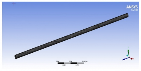
The Ansys program simulated the pipe model of the air conditioning system. Where the surface of the air conditioning pipe was designed with a diameter of 10 mm and a length of 500 mm, representing a general model for air conditioning pipes, where fiber-class and carbon-fiber layers were added in a way that represents each layer 1 mm, where the thickness of the pipe became 3 mm, see Figure 1.
After the process of forming the model, a good mesh must be made to obtain accurate results commensurate with the simulation mechanism, as the reliability of the network was made as in the following Table 1.
ANSYS provides a large library of materials that can be used in simulations, including metals, plastics, composites, and more. The materials library is constantly updated and expanded to include new materials and their properties, ANSYS provides a comprehensive library of composite materials, including carbon fiber, glass fiber, Kevlar, and others. These materials can be used to simulate the behavior of composite structures, such as laminates and sandwich panels. a comprehensive library of materials that can be used in simulations, and engineers can also define custom materials based on their specific requirements.
The layers textures were obtained through the library of materials in the ANSYS program and added them to the processor, which arranges these layers in a controlled geometric shape, see Table 2 and Figures 2 and 3. The type element was tetrahedron because the shape is cylinder to give more quality to mesh, see Figure 4.
Figure 1. Geometry of the pipe
Table 1. Mesh independency
|
Case |
Element |
Node |
Deformation (m) at 100 N load, arrangement (0,0,90) |
|
1 |
6244 |
6342 |
0.0214 |
|
2 |
10675 |
10845 |
0.0197 |
|
3 |
12356 |
12457 |
0.016 |
|
4 |
15407 |
15438 |
0.0159 |
Table 2. Angular orientation of fiber layers thickness 1 mm for each layer
|
Angle |
||||||
|
Material |
case1 |
case2 |
case3 |
case4 |
case5 |
case6 |
|
Carbon fiber |
0 |
90 |
45 |
90 |
45 |
45 |
|
Glass fiber |
0 |
0 |
0 |
0 |
0 |
0 |
|
Carbon fiber |
90 |
0 |
45 |
45 |
90 |
0 |
|
Material |
case7 |
case8 |
case9 |
case10 |
case11 |
case12 |
|
Carbon fiber |
0 |
30 |
45 |
45 |
90 |
90 |
|
Glass fiber |
0 |
0 |
0 |
0 |
0 |
0 |
|
Carbon fiber |
45 |
15 |
15 |
30 |
15 |
30 |
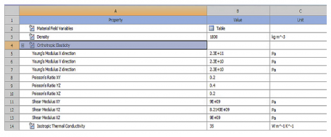
Figure 2. Properties of carbon fiber [15]
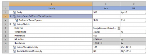
Figure 3. Properties of glass fiber [15]
Figure 4. Mesh
One of the key components of ANSYS is the ANSYS Composite Prep Post (ACP), which is a pre- and post-processing tool designed specifically for composite materials. ACP allows engineers to create, analyze, and optimize composite structures, including laminates, sandwich panels, and reinforced plastics. ACP is a powerful tool for designing and analyzing composite structures, and it is widely used in industries such as aerospace, automotive, and marine engineering.
Where the ACP processor was used to organize the fiber layers, and a group of arrangement methods were taken to see the best arrangement that can be obtained through the simulation process, to represent the optimal way to arrange that can be used practically in the formation of conditioning pipes from these materials, see Table 3.
Table 3. Angular orientation of fiber layers in different thickness
|
Material |
Arrangement |
Thickness |
||
|
case 1 |
case 2 |
case 3 |
||
|
Carbon fiber |
45 |
1 mm |
2 mm |
3 mm |
|
Glass fiber |
0 |
1 mm |
2 mm |
3 mm |
|
Carbon fiber |
90 |
1 mm |
2 mm |
3 mm |
It would be better to improve the parameters such as different thickness and other angular orientations like 30, 15 degrees. Study on it and offer me.
Where the layers were divided in terms of the angle of rotation of the layer, and after the process of arranging the layers, a force was added to the edge of the pipe by 100 N with the negative Y axis. A constant force must be applied to the surfaces to make them a source for comparison, as the expected force acting on the conditioning pipe reaches 100 N, which is sufficient to see the stresses and deformations and compare them with the other end, which was fixed to see the greatest stress that can be gotten. Because of the effect of the conditioning gas inside the tube, its reaction force is almost non-existent, and because the study was based on a program that simulates deformations and stresses, it was necessary to focus on the matter. As for the limitation used in this paper, it was neglected the impact coming from the gas used in the cooling system. As well as the vertical and horizontal twists, that occur in the arrangement of the cooling system pipes.
These equations and their description were obtained from the ANSYS program [15].
The governing equations for linear structural static analysis in ANSYS are based on the principles of linear elasticity, which describe the behavior of materials under small deformations. The equations are derived from the equations of equilibrium, strain-displacement relationships, and constitutive laws, which relate stresses and strains to material properties. The governing equations for linear structural static analysis in ANSYS are then obtained by combining the equations of equilibrium, strain-displacement relationships, and constitutive law, and applying the finite element method to discretize the equations into a set of algebraic equations that can be solved numerically. The finite element method involves dividing the structure into a set of discrete elements, and using the equations of equilibrium, strain-displacement relationships, and constitutive law to formulate a system of equations for each element. These equations are then assembled into a global system of equations for the entire structure, which can be solved numerically to obtain the displacements and stresses in the structure. the governing equations for linear structural static analysis in ANSYS are derived from the principles of linear elasticity, and are based on the equations of equilibrium, strain-displacement relationships, and constitutive law. These equations are discretized using the finite element method and solved numerically to obtain the displacements and stresses in the structure.
The overall equilibrium equations for linear structural static analysis are:
$[K]\{u\}=\{F\}$ (1)
or
$[K]\{u\}=\left\{F^a\right\}+\left\{F^r\right\}$ (2)
where,
[K]= $\sum_{m=1}^N\left[K_e\right]$=total stiffness matrix (N/m)
{u}=nodal displacement vector (m)
N=number of elements
$\left[K_e\right]$=element stiffness matrix (described in Element Library) (may include the element stress stiffness matrix (described in Stress Stiffening)) (N/m)
$\left\{F^r\right\}$=reaction load vector (N)
$\left\{F^a\right\}$, the total applied load vector, is defined by: (N)
$\left\{F^a\right\}=\left\{F^{n d}\right\}+\left\{F^{a c}\right\}+\sum_{m=1}^N\left(\left\{F_e^{t h}\right\}+\left\{F_e^{p r}\right\}\right)$ (3)
where,
$\left\{F^{n d}\right\}$=applied nodal load vector (N)
$\left\{F^{a c}\right\}=-[M]\left\{a_c\right\}$=acceleration load vector (m2/s)
$[M]=\sum_{m=1}^N\left[M_e\right]=$total mass matrix (kg)
$\left[M_e\right]$=element mass matrix (described in Derivation of Structural Matrices) (kg)
$\left\{a_c\right\}$=total acceleration vector (defined in Acceleration Effect) (m2/s)
$\left\{F_e^{t h}\right\}$=element thermal load vector (described in Derivation of Structural Matrices) (N)
$\left\{F_e^{p r}\right\}$=element pressure load vector (described in Derivation of Structural Matrices) (N).
4.1 ACP results
The ACP processor arranges the fiber layers in a controlled manner. It is known that several layers were arranged at different angles, and the polar properties, which contributes to knowing the optimum angle, arrangement of layers, and layer thickness.
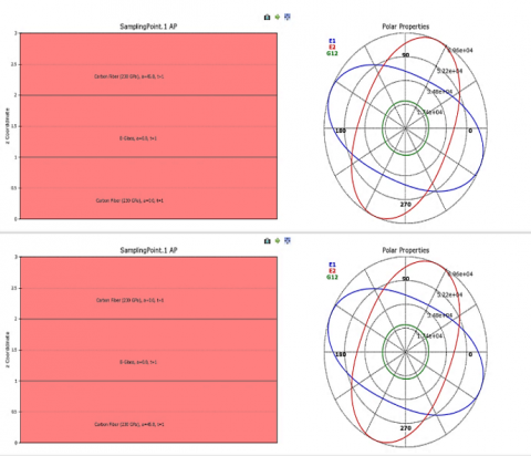
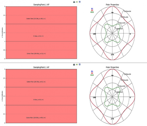
Figure 5. Polar properties of arrangement of 0,0,45 and 45,0,0 degree
Through the polar properties shown in Figure 5, note that the inverse arrangement does not affect the polar properties, but later on greatly affects the high distortions and stresses, as note that E1 was 34800 MPa, that E2 reached to 69600 MPa and G12 is 17400 MPa.
Figure 6. Polar properties of arrangement of 0,0,90 and 90,0,0 degrees
Through the polar properties shown in Figure 6, note that the inverse arrangement does not affect the polar properties, but later on, greatly affects the high distortions and stresses, as note that E1 was 43700 MPa, that E2 reached to 43700 MPa and G12 is 14600 MPa.
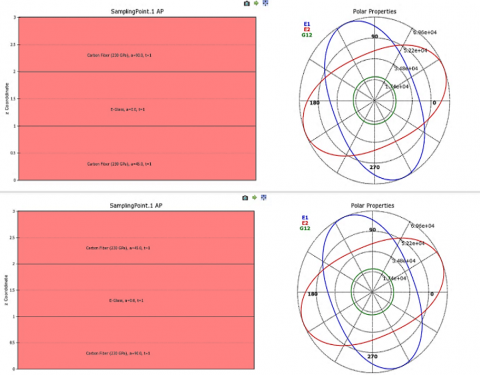
Figure 7. Polar properties of arrangement of 45,0,90 and 90,0,45 degrees
Through the polar properties shown in Figure 7, note that the inverse arrangement does not affect the polar properties, but later on greatly affects the high distortions and stresses, as note that E1 was 34800 MPa, that E2 reached to 52200 MPa and G12 is 17400 MPa.
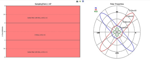
Figure 8. Polar properties of arrangement of 45,0,45 degrees
Through the polar properties shown in Figure 8, note that the inverse arrangement does not affect the polar properties, but later on greatly affects the high distortions and stresses, as note that E1 was 88600 MPa, that E2 reached to 133000 MPa and G12 is 44300 MPa.
From Figures 5-8, the arrangement of the polarity properties gives an indication of the extent of the material's tolerance to stresses and strains. It is extracted from the previous Figures that the best shape of the polar was given by 0,0,90, due to the distribution of the strength of the composite material because of different directions and able to withstand different conditions of stresses and deformations, and this is what has been proven in the simulation results.
4.2 Static result for deferent agreement
The mechanical properties of composite air conditioning pipes can be affected by the arrangement or agreement of the layers of composite materials. The orientation of the fibers within each layer of the composite material can affect the strength and stiffness of the pipe. For example, fibers oriented in the longitudinal direction can increase the strength and stiffness of the pipe in that direction, while fibers oriented in the transverse direction can increase resistance to bending. The symmetry of the composite material layers can affect the mechanical properties of the pipe. Symmetrical layering can improve the overall strength and stiffness of the pipe and provide a more uniform distribution of stresses within the material. Random layer arrangements can provide some advantages in terms of impact resistance and damage tolerance. The randomness of the layer arrangement can help to distribute stresses more evenly throughout the material, reducing the risk of localized failure. The sequence in which the layers of composite materials are stacked can affect the mechanical properties of the pipe. Different stacking sequences can be used to optimize specific properties, such as strength, stiffness, or impact resistance. Different composite materials have different mechanical properties, and the arrangement of the layers of these materials can affect the overall mechanical properties of the pipe. For example, using carbon fibers in a composite material can increase the strength and stiffness of the pipe compared to fiberglass. In general, the effects of different layer arrangements will depend on the specific application and the desired mechanical properties of the pipe. Careful consideration of the trade-offs between strength, stiffness, impact resistance, and other properties will be necessary to determine the optimal layer arrangement for a given application.
The static processor simulates the stresses and deformations that get on the pipe by applying the layers arrangement and adding loads 100 N to it.
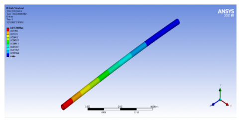
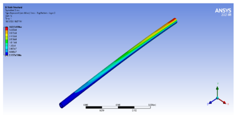
Figure 9. Deformation of 45,0,90 degree
Through the previous form of deformation shown in Figure 9, note that the least deformation reached by the layers by dividing them through the angle difference is in the order 45,0,90 from the center, where the deformation reached 0.0157 m and is considered the least deformation compared to the rest.
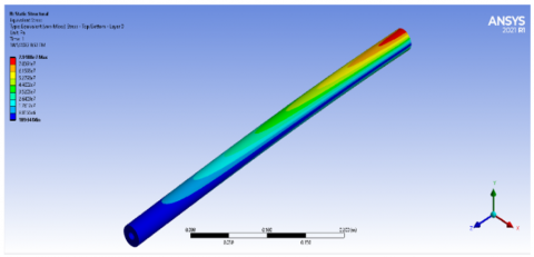
Figure 10. Equivalent stress of 45,0,90
Figure 10 represents the stress that occurs in the installation region of the pipe, as the least deformation occurred in the order of 45,0,90 and the greatest stress reached in this order, where the stress reached 362.27 MPa, which represents the highest stress compared to the rest.
Table 4. Arrangement of fiber layers and stresses
|
Angle |
||||||
|
Material |
case1 |
case2 |
case3 |
case4 |
case5 |
case6 |
|
Carbon fiber |
0 |
90 |
45 |
90 |
45 |
45 |
|
Glass fiber |
0 |
0 |
0 |
0 |
0 |
0 |
|
Carbon fiber |
90 |
0 |
45 |
45 |
90 |
0 |
|
Deformation (m) |
0.0159 |
0.023 |
0.0468 |
0.0224 |
0.0157 |
0.0474 |
|
Stress (MPa) |
357.5 |
314.75 |
237.13 |
305.4 |
362.27 |
147.75 |
|
Material |
case7 |
case8 |
case9 |
case10 |
case11 |
case12 |
|
Carbon fiber |
0 |
30 |
45 |
45 |
90 |
90 |
|
Glass fiber |
0 |
0 |
0 |
0 |
0 |
0 |
|
Carbon fiber |
45 |
15 |
15 |
30 |
15 |
30 |
|
Deformation (m) |
0.0446 |
0.0519 |
0.0478 |
0.0501 |
0.0236 |
0.023.6 |
|
Stress (MPa) |
227.55 |
139.22 |
136.51 |
127.88 |
318.4 |
320.2 |
Through Table 4, note that the arrangement of the layers on the tube improves the mechanical properties of the tube through the different angles of the fiber, where note that the best quality of arrangement is at 45,0,90 compared to the rest of the formulas.
4.2 Static result for deferent thickness
Increasing the thickness of composite material layers in air conditioning pipes can have several effects on the mechanical properties of the pipe. Thicker composite layers can increase the overall strength of the pipe, making it more resistant to damage and deformation. This is particularly important in applications where the pipe may be subjected to high pressure or external forces. Thicker composite layers can also increase the stiffness of the pipe, making it more resistant to bending and twisting. This can be important in applications where the pipe needs to maintain its shape and integrity over time. Thicker composite layers can reduce the flexibility of the pipe, which can be a disadvantage in some applications where the pipe needs to be able to bend or flex without breaking. Thicker composite layers will increase the weight of the pipe, which can be a disadvantage in applications where weight reduction is a priority, such as in the aerospace or automotive industries. Thicker composite layers can improve the thermal insulation properties of the pipe, which can be important in air conditioning applications where heat loss needs to be minimized. the effects of increasing the thickness of composite material layers in air conditioning pipes will depend on the specific application and the performance requirements of the pipe. Careful consideration of the trade-offs between strength, stiffness, flexibility, weight, insulation, and cost will be necessary to determine the optimal thickness for a given application.
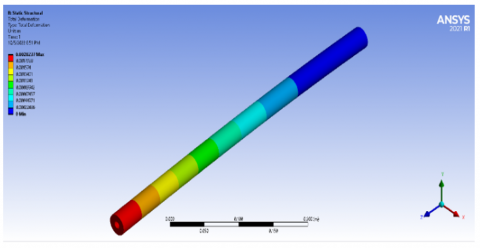
It is necessary to study the variable thickness in the simulated cases to obtain the best resistance to deformation in the tube. Where the best case was taken into account in terms of the arrangement of the layers and angles used, and thickness changes were applied to them. The results proved the effectiveness of increasing the thickness in improving the resulting deformations. Notice from Figure 11 that the value of the deformations was less when the thickness values for the layers were 3 mm. compared to 2 mm. As the value of the distortions reached 0.002 m, which is the lowest value of distortion that has been reached compared to the remaining cases.
Figure 12 represents the stress that occurs in the installation region of the pipe, as the least deformation occurred in the order of 45,0,90 at thickness 3 mm, where the stress reached 79.188 MPa.
Figure 11. Deformation of 45,0,90 degree at thickness 3 mm
Figure 12. Equivalent stress 45,0,90 degree at thickness 3 mm
Table 5. Arrangement of fiber layers and stresses at deferent thickness
|
Material |
Arrangement |
Thickness |
||
|
case 1 |
case 2 |
case 3 |
||
|
Carbon fiber |
45 |
1 mm |
2 mm |
3 mm |
|
Glass fiber |
0 |
1 mm |
2 mm |
3 mm |
|
Carbon fiber |
90 |
1 mm |
2 mm |
3 mm |
|
Deformation (m) |
|
0.0157 |
0.0046 |
0.0020 |
|
Stress (MPa) |
|
362.27 |
143.72 |
79.188 |
Through Table 5, note the effectiveness of increasing the thickness in reducing stress and increasing the pipe’s tolerance against the deformations that it obtains.
The process of improving the tube of the air conditioning system was carried out by adding fiber materials that improve the mechanical properties in terms of arranging the fiber layers at different angles. Whereas gas leakage issues have developed into one of the most significant issues in air conditioning organizations, the solution to these issues looks forward to improving the gas connection pipes in air conditioning companies and enhancing their durability. The goal of the study presented in this research paper is to improve gas pipes by adding insulating and supporting layers to increase the pipe's durability, such as layers of carbon and fiber. Through Simulation, materials have been added at various angles and directions to determine the best accessible condition to improve the condition of the ionization tube. The most important results showed that the condition of arrangement 45,0,90 is the best state reached by the deformation, where the distortion was 0.0157 m, as for the most deformation reached. It is the order of 45,0,0, where the deformation reached 0.0474 m, which is the worst case. As for the stresses, the most stressful condition is in the case of the least distortion, where the stress reached 362.2 MPa, and the least stress was borne by the tube is in the order 45,0,0 where the stress was reduced to 147.7 MPa. A study has shown the effectiveness of increasing the thickness in improving the resulting deformations. The least deformation occurred in the order of 45,0,90 at thickness 3 mm, where the stress reached 79.188 MPa. The value of the distortions reached 0.002 m, which is the lowest value of distortion that has been reached compared to the remaining cases. Where the author recommends, in future works, to apply the parameters and results obtained experimentally and compare them with the numerical aspect to benefit from them in real applications.
The authors would like to thanks Al-Mustaqbal University College for the assistance in completing this work.
[1] Huang, Z., Qian, X., Su, Z., Pham, D.C., Sridhar, N. (2020). Experimental investigation and damage simulation of large-scaled filament wound composite pipes. Composites Part B: Engineering, 184: 107639. https://doi.org/10.1016/j.compositesb.2019.107639
[2] Khudayarov, B.A., Komilova, K.M., Turaev, F.Z., Aliyarov, J.A. (2020). Numerical simulation of vibration of composite pipelines conveying fluids with account for lumped masses. International Journal of Pressure Vessels and Piping, 179: 104034. https://doi.org/10.1016/j.ijpvp.2019.104034
[3] Khudayarov, B.A., Komilova, K.M., Turaev, F.Z. (2019). Numerical simulation of vibration of composite pipelines conveying pulsating fluid. International Journal of Applied Mechanics, 11(9): 1950090. https://doi.org/10.1142/S175882511950090X
[4] Maung, P.P., Htet, T.L., Malysheva, G.V. (2020). Simulation and optimization of vacuum assisted resin infusion process for large-sized structures made of carbon fiber-reinforced plastics. In IOP Conference Series: Materials Science and Engineering, 709(2): 022041. https://doi.org/10.1088/1757-899X/709/2/022041
[5] Brenken, B., Barocio, E., Favaloro, A., Kunc, V., Pipes, R.B. (2019). Development and validation of extrusion deposition additive manufacturing process simulations. Additive Manufacturing, 25: 218-226. https://doi.org/10.1016/j.addma.2018.10.041
[6] Carrino, S., Maffezzoli, A., Scarselli, G. (2021). Active SHM for composite pipes using piezoelectric sensors. Materials Today: Proceedings, 34: 1-9. https://doi.org/10.1016/j.matpr.2019.12.048
[7] Ghasemi, A.R., Taheri-Behrooz, F., Shokrieh, M.M. (2021). Measuring residual stresses in composite materials using the simulated hole drilling method. In Residual stresses in composite materials, pp. 111-162. https://doi.org/10.1533/9780857098597.1.76
[8] Rafiee, R., Abbasi, F. (2020). Numerical and experimental analyses of the hoop tensile strength of filament-wound composite tubes. Mechanics of Composite Materials, 56: 423-436. https://doi.org/10.1007/s11029-020-09894-2
[9] Amir-Ahmadi, S., Ghasemi, A.R. (2020). Experimental investigation of cooling conditions, MWCNTs and mandrel diameter effects on the thermal residual stresses of multi-layered filament-wound composite pipes. Journal of Composite Materials, 54(30): 4773-4786. https://doi.org/10.1177/0021998320937759
[10] Sommer, D.E., Kravchenko, S.G., Denos, B.R., Favaloro, A.J., Pipes, R.B. (2020). Integrative analysis for prediction of process-induced, orientation-dependent tensile properties in a stochastic prepreg platelet molded composite. Composites Part A: Applied Science and Manufacturing, 130: 105759. https://doi.org/10.1016/j.compositesa.2019.105759
[11] Amini Niaki, S., Forghani, A., Vaziri, R., Poursartip, A. (2019). An orthotropic integrated flow-stress model for process simulation of composite materials—Part II: Three-phase systems. Journal of Manufacturing Science and Engineering, 141(3): 031011. https://doi.org/10.1115/1.4041862
[12] Grosso, M., de Araújo Soares, I., Lopez, J.E., Soares, S. D., Rebello, J.M., Pereira, G.R. (2019). Study on the limit detection of defects by pulsed thermography in adhesive composite joints through computational simulation. Composites Part B: Engineering, 168: 589-596. https://doi.org/10.1016/j.compositesb.2019.03.083
[13] Sommer, D.E., Kravchenko, S.G., Pipes, R.B. (2020). A numerical study of the meso-structure variability in the compaction process of prepreg platelet molded composites. Composites Part A: Applied Science and Manufacturing, 138: 106010. https://doi.org/10.1016/j.compositesa.2020.106010
[14] Sádaba, S., Herráez, M., Naya, F., González, C., Llorca, J., Lopes, C.S. (2019). Special-purpose elements to impose periodic boundary conditions for multiscale computational homogenization of composite materials with the explicit finite element method. Composite Structures, 208: 434-441. https://doi.org/10.1016/j.compstruct.2018.10.037
[15] ANSYS. (2017). Engineering Simulation Software. https://www.ansys.com.