Ahmed Youcef* | Rachid Saim
© 2022 IIETA. This article is published by IIETA and is licensed under the CC BY 4.0 license (http://creativecommons.org/licenses/by/4.0/).
OPEN ACCESS
A numerical simulation of a turbulent flow of water in three shell and tube heat exchangers equipped with 6, 8, 10 segmental baffles as the working fluid at Reynolds numbers ranging from 24327, 33356, 42569 are performed. The conservation equations of mass, momentum and energy are solved by the finite volume method based on the SIMPLE algorithm for coupling velocity-pressure, the mathematical model k-ε within the Fluent software is used in the different cases presented. The temperature, the velocity, the friction factor, the heat transfer coefficient, the pressure drop in the shell, the total heat transfer rate between the tubes and the fluid, the overall performance factor are studied for the three spacing between baffles. This work contributes largely to the understanding of turbulent flows and also shows the effect of the baffles number on the heat transfer in the heat exchangers. The velocity of flow in the shell increases by 1.49% and 1.62% and 1.73% of the reference velocity. The results show an increase in the outlet temperature, heat transfer coefficient 1.09% and 1.28%, pressure drop 1.7% and 2.82%, the total heat transfer rate 1.08% and 1.18% because of the increase in number of baffles. The results obtained in this study are in good agreement and correspond to the results given by the literature.
baffle, shell and tube heat exchanger, CFD
The tubular heat exchangers contain a number of tubes packed in a shell with their axes parallel to that of the shell. The process of heat transfer takes place as a fluid flow into the tubes, while the other fluid flows to the side of the shell through the bundles of tubes. Baffles are used to control the distribution of the shell side flow as well as the improvement of heat transfer. In recent years, shell and tube heat exchangers are widely used in many fields of engineering such as chemical engineering processes, power generation, petroleum refining, refrigeration, air conditioning, the food industry [1]. The shell-and-tube heat exchangers are relatively simple to manufacture, and offer versatile application in comparison with other types of heat exchangers [2], it is reported that more than 30% of the heat exchangers used are of the type shell tube [3].
Among the works carried for this type of heat exchanger, Gao et al. [4]. the authors carried experimental studies on discontinuous helical baffles at different angles 8°, 12°, 20°, 30° and 40° and reported that the performance of the helix angle 40° is the best among those tested. You et al. [5]. developed numerical model a two-section segmental baffle over a Reynolds range from 6813 to 22326 for the shell side, the results of the simulations prove that the flow regime is different and has a better overall thermal performance than the heat exchanger with unique segmental baffles. Wang et al. [6]. carried experimental research on heat exchangers with segmental baffles and the two-section, the model with two sections reported was 20 to 30% more efficient than that of the segmental baffle under the same operating conditions. Ma’arof et al. [7]. Investigates the effects of diverse designs default, angled, perforated and coated for the rate of heat transfer in heat exchanger, the coating on the fins was decreasing the temperature at a much higher margin at all fan speeds. Youcef et al. [8] studied numerically the performance of new type baffles and show that the wing shape serves to promote a complete mixing of the fluid. Youcef et al. [9, 10] in order to understand the effect of the use of baffles in the heat exchanger, a comparative study was presented and show that the heat transfer coefficient and the pressure drop increase by 1, 86% and 21.67%. Youcef et al. [11] studied three baffles inclination angles 10°, 20°, 40°. The results show that the heat transfer coefficient and the pressure drop decreased by 0.983% and 0.992% respectively with increasing inclination. Cucumo et al. [12], show that decrease in pressure drop with increasing helix angle. Dipankar et al. [13], the heat transfer coefficient increases with the increase of velocity.
Reducing the baffles spacing has a petal effect on the heat transfer because the increase in the baffles number increases the residence time and the fluid particle trajectory length in the shell therefore a higher heat transfer between the tubes and the fluid consequently a considerable increase in the thermal performance of the heat exchanger, the present study examines numerically in 3D using the FLUENT code, the thermo-hydraulic performances of an effect of the baffles spacing, namely, 86 mm, 67 mm, and 55 mm, with a mass flow rate of 1 kg/s will be discussed, the choice of the baffles spacing was selected from the curve recommended by Taborek [14] for the segmental baffles in the case without phase change.
The numerical analysis is carried to study the appropriate modifications made to apply a comparative analysis between the thermal and hydraulic parameters of the three heat exchangers to indicate their advantages and disadvantages. The numerical results are presented in terms of the outlet temperature, the velocity, the friction factor, the heat transfer coefficient, the pressure drop, the total heat transfer rate and the overall performance factor.
2.1 Geometry of the problem
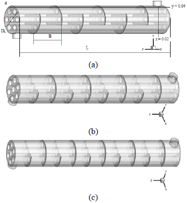
The studied configurations and the thermal coordinate system considered in this study are illustrated in Figure 1. The effects of baffles spacing on the heat transfer and pressure drop for water are investigated for different number of baffles (6, 8 and 10). The geometric dimensions of the problem are mentioned in Table 1 which is taken from the Ozden et al. [15].
Figure 1. Geometry of the problem
Table 1. Geometric parameters of the heat exchanger
|
Shell diameter (mm) |
Ds = 90 |
|
Tube diameter (mm) |
d = 20 |
|
Tube bundle geometry and pitch (mm) |
Triangular,P=30 |
|
Number of tubes |
Nt = 7 |
|
Tube length (mm) |
L = 600 |
|
Shell side inlet temperature (K) |
Te = 300 |
|
Baffle cut |
36% |
|
Number of baffles |
Nb = 6, 8, 10 |
|
Baffle spacing (mm) |
B=86, 67, 55 |
2.2 Gouverning equation
Continuity
$\frac{\partial\left(\rho \cdot u_{i}\right)}{\partial x_{i}}=0$ (1)
Momentum
$\frac{\partial {{u}_{i}}{{u}_{j}}}{\partial {{x}_{i}}}=-\frac{1}{\rho }\frac{\partial P}{\partial {{x}_{i}}}+\frac{\partial }{\partial {{x}_{j}}}\left( \left( \nu +{{\nu }_{t}} \right)\left( \frac{\partial {{u}_{i}}}{\partial {{x}_{j}}}+\frac{\partial {{u}_{j}}}{\partial {{x}_{i}}} \right) \right)$ (2)
Energy
$\frac{\partial \left( {{u}_{i}}T \right)}{\partial {{x}_{i}}}=\rho \frac{\partial }{\partial {{x}_{i}}}\left( \left( \frac{\nu }{\Pr }+\frac{{{\nu }_{t}}}{{{\Pr }_{t}}} \right)\frac{\partial T}{\partial {{x}_{i}}} \right)$ (3)
The heat transfer rate:
$Q=\overset{\bullet }{\mathop{m}}\,{{C}_{p,eau}}\left( {{T}_{out}}-{{T}_{in}} \right)=hA\left( {{T}_{w}}-{{T}_{b}} \right)$ (4)
where, Cp is the specific heat capacity, Tin, Tout is the inlet and outlet water temperature.
With:
${{T}_{b}}=\frac{{{T}_{out}}+{{T}_{in}}}{2}$ (5)
The pressure drop:
$\Delta p=\frac{f G_{s}^{2}\left(N_{b}+1\right) D}{2 \rho_{s} D_{e} \phi_{s}}$ (6)
The improvement factor $\eta$:
$\eta =\left( \frac{Nu}{N{{u}_{0}}} \right){{\left( \frac{f}{{{f}_{0}}} \right)}^{-1/3}}$ (7)
where, h is the average heat transfer coefficient, Nu is the Nusselt number, Nu0 and f0 is the Nusselt number and the friction coefficient of the base case.
2.3 Boundary conditions
A uniform velocity (v= 0.4 m/s) was applied as a boundary condition to the hydraulic input of the computational domain obtained according to the imposed mass flow rate of 1 kg/s and the section of the shell inlet. In addition, as a condition for the thermal limit, a constant temperature of Tw=177℃ (450 K) was applied on the walls of the tubes. The temperature of the fluid used was set at Tin=27℃ (300 K) to the inlet of the shell.
Table 2. Pressure drop in the shell
|
Number of baffles |
ΔP (Pa) |
Déférence% |
|
|
|
CFD |
Analytic |
|
|
6 |
5475 |
4955 |
10.5 |
|
8 |
9344 |
8874 |
5.3 |
|
10 |
15460 |
14996 |
3.1 |
The average error of pressure drop between analytical and numerical calculations having 6.3% in Table 2.
4.1 Dynamic behavior
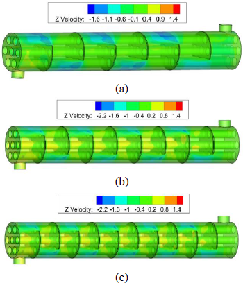
In Figure 2, the velocity contours are presented for the three numbers of the baffles for mass flow rate of 1 kg/s. The velocity near the tube is zero justified by the color and the negative values indicate directions of the flow. The velocity field pattern repeats in each case between two baffles located in the same shell side are a cycle, an inner flow occurs in the beginning of each cycle is a vortex. The maximum velocity for 6, 8, 10 baffles are 1.6 m/s, 2.2 m/s, and 2 m/s respectively, so there is an increase in the velocity of the flow with the decrease of the space between the baffles. The velocity field has a periodic distribution around the central axis of the heat exchanger.
Figure 2. Velocity contour
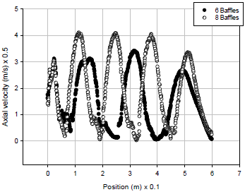
Figure 3. Longitudinal velocity
A presentation of the velocity distribution at y = 0.04 m of the two exchangers with 6 and 8 baffles shown in Figure 3. The velocity has a periodic distribution around the central axis and the difference lies in the velocity amplitude because there is an increase in velocity with the increase in the baffles number.
For the 6 baffles the fluid velocity reached 1.35m/s, after 1st baffle, then 1.7 m/s after 3rd baffle, 1.5 m/s downstream of the baffle, and outlet by 1.5 m/s. For the 8 baffles the fluid velocity reach 1.7 m/s, after 1chicane 2m/s after the 3rd, 5th, 7th baffles, to 1.5 m/s to the outlet. It can be seen that the velocity gradient in the heat exchanger with 8 baffles is very high. The velocity curves show that the fluid velocity is higher in the small distance between the baffles. In this case, the cross flow area is smaller and generates a higher velocity.
There is an increase in the velocity of the flow with the increase in the number of baffles therefore the reduction in the space between the baffles this variation can be quantified from the Eq. (6) therefore: $u=\sqrt{\frac{2 \rho_{s} D_{d} \phi_{s} \Delta p}{f D\left(N_{b}+1\right)}}$.
With the increase in the number of baffles there is an increase in the number of recirculation zones, the volume of the recirculation zone reduces the passage area of the main flow and undergoes an increase in velocity.
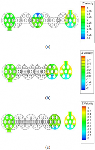
Figure 4. Velocity contours (m/s) for z = 0.58 and z = 0.02: (a) 6 baffles, (b) 8 baffles, (c) 10 baffles
In Figure 4, the velocity contours are presented to give images of the flow distribution at the outlet for the three heat exchangers.
High velocity is restricted, especially in the circumferential zone of the shell. There are low velocity areas, mainly on the upper side of the three central tubes. The high number of baffles results in higher flow resistance and recirculation zones.
4.2 Pressure drop
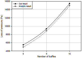
Figure 5 shows trends in the pressure drop variation and number of baffles. The numerical values calculate at the outlet the shell. The average error of pressure drop between analytical and numerical calculations having 4.3%. Analytical calculations take into account friction coefficient values with three digits after the decimal point and numerical calculations take all digits into consideration.
The numerical pressure drop it is found that the higher pressure drop value 15460 Pa for the higher baffle number and that the value of the lower pressure drop 5475 Pa for a reduced number of baffles.
The pressure drop is influenced by the number of baffles; the distance between the baffles is inversely proportional to the number of baffles.
The higher number of baffles causes a small area of transverse flow that passes through the outer walls of the tubes and increases the pressure drop and cause energy dissipation.
Figure 5. Pressure drop in the shell
4.3 Thermal behavior
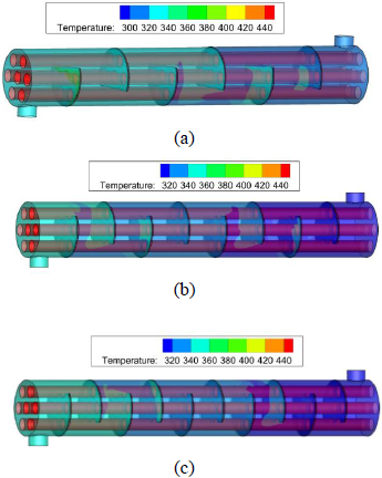
Figure 6. Temperature contour
Figure 6 shows the temperature distribution in the section that contains the central tube. The temperature range of these three configurations is quite different, given the disposition of the baffles and the periodicity of the flow on the side of the shell. It can be observed that the fluid temperature increases along the heat exchanger and with the increase in number of baffles. Regions at high temperatures are located near tubes and at the end of each cycle.
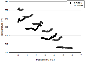
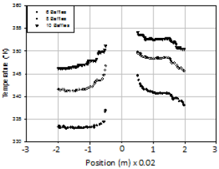
Figure 7. Temperature profile y = 0.04
A presentation of the temperature distribution along the two heat exchangers with 6 and 10 baffles at the section y = 0.04 m illustrated in Figure 7. It is found that the fluid temperature increases from entering at the outlet for both cases, and from one cycle to another. The intermittent noted is the passage of the section presented to the baffles in the two cases studied because the fluid domain was presented.
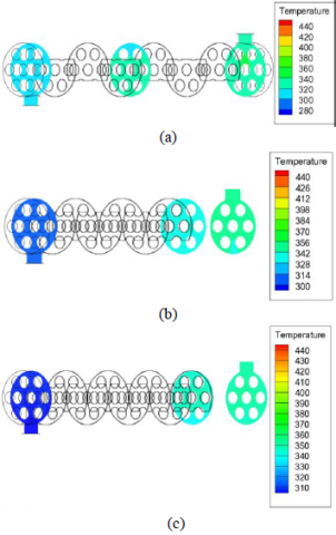
Figure 8. Temperature contours at z = 0.02: (a) 6 baffles, (b) 8 baffles, (c) 10 baffles
For the 6 baffles the fluid temperature at the outlet is 340 K, for the 10 baffle the fluid temperature increases to 353 K.
Increasing the number of baffles increases the fluid path length and recirculation zones and increases the temperature.
Figure 8 shows the variations in temperature for the three selected configurations, the selected section contains 7 tubes in 3 rows in a shell for further study. For the configuration of 8 baffles the distribution of the thermal field is higher in the vicinity of the tubes and between the tubes of the upper part of the shell.
Figure 9. Temperature profile z = 0.02
In Figure 9 we have a presentation of the velocity curve in the section z = 0.02m for the three cases, the fluid temperature increases close to the central tube and decreased when away from.
The temperature of the outlet of this section is: 338 K for (6) baffles, 346 K for (8) baffles, 351 K for (10) baffles, so there is an increase in the fluid temperature in the shell with the increase of the number of baffles.
Increasing the number of baffles will increase the flow path and flow turbulence along the tubes, which will increase the fluid temperature.
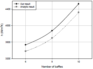
4.4 Average heat transfer coefficient of water
Figure 10. Average heat transfer coefficient
Figure 10 shows the variation of the average heat transfer coefficient by different spaces between the baffles. The effect of the spacing between baffles on the average heat transfer coefficient is visualized because its numerical value increases by 3532 W/m2K for (6) baffles at 4528 W/m2K for (10) baffles, it is shown that the heat transfer coefficient increases with increasing number of baffles. Increasing the number of baffles will increase the fluid velocity in the shell and cause an increase in the number of swirl zones after the baffles; hence the value of the heat transfer coefficient will increase.
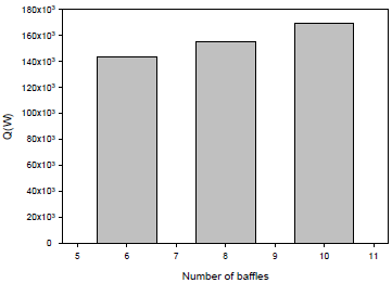
4.4 Total heat transfer rate
A comparison of the total heat transfer rate between the tubes and the fluid circulated in the shell for the heat exchangers shown in Figure 11. The total heat transfer rate increases with increasing number of baffles, when the number of baffles increases from 6 to 10, the total heat transfer rate increases by 1.08% for the heat exchanger with 8 baffles and 1.18% for the heat exchanger with 10 baffles. With the increase in the baffles number there is an increase in heat transfer coefficient with an increase in temperature which causes an increase in heat transfer rate according to Eq. (4).
Figure 11. Total heat transfer rate for different cases
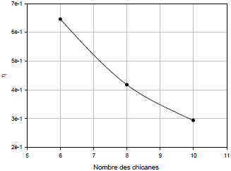
4.6 Overall performance factor
Figure 12 shows the variation in overall performance for different numbers of baffles. With the increase in baffles number in 8 to 10, the overall performance factor decreased by 1.546% and 2.201%. With the increase in the baffles number there is a very significant increase in pressure drop which negatively influences the overall performance factor.
Figure 12. Overall performance factor
A numerical study of the thermo-energetic performances of three shell and tube heat exchangers equipped with different spaces between the baffles namely, 87 mm, 67 mm and 55 mm for the turbulent regime, Reynolds number of 24327, 33356 and 42569 was carried followed by analytical results to judge these parameters. The numerical and analytical results are compared and it was found that the numerical results were in good agreement with the analytical results. The effects of thermo-hydraulic modification by the baffles number in the shell and tube heat exchanger are presented. The most important conclusions that can be drawn from this study are:
It is confirmed that the performance of the heat exchanger can be improved by the increase of baffles number. Higher velocity gradients are observed at the end of the baffles. The temperature around the central tube is much higher than that of the peripheral tubes. The heat transfer coefficients for the whole scheme presented increases with the periodicity of the cycles along the axial direction. The uses of the small spaces between baffles intensify the turbulence near the bundle of tubes and increase the fluid temperature. For the three schemes the higher spaces between baffles have the lowest pressure drop. The heat transfer coefficient and the pressure drop on the shell side increased with increasing baffles number. The baffles number influences in the friction between the fluid and the baffle surface and causes energy dissipation. The results show that the scheme with 10 baffles not only has the positive characteristics with respect to heat transfer, but also an increase in the number of stagnant zones, the increase in pressure drop on the shell side. Comparing the characteristics of the heat exchanger with 10 baffles by 8 and 6 baffles found: the heat transfer coefficient is much higher than that of the other exchangers, 1.09% and 1.28%, the pressure drop on the shell side increases with increasing of baffles number, in note 1.7% and 2.82%, the total heat transfer rate increases by 1.08% and 1.18%.
The overall performance factor decreased by 1.546% and 2.201% because of the increase in the pressure drop.
|
Ds |
Shell size (mm) |
|
d |
Tube diameter (mm)specific |
|
Nt |
Number of tubes |
|
L |
Heat exchanger length (mm) |
|
Nu |
local Nusselt number along the heat source |
|
Nu0 |
Nusselt number of the base case |
|
T |
Shell side inlet temperature (°K) |
|
Tin |
Inlet temperature, K |
|
Tout |
Outlet temperature, K |
|
Gs |
Shell-side mass flow rate, kg/s |
|
w |
wall |
|
Bc |
Baffle cut (%) |
|
Nb |
Number of baffles |
|
h |
Heat transfer coefficient (W/(m2K) |
|
u, v, w |
velocity components (m/s) |
|
x, y, z |
positions coordinates |
|
m |
Mass flow rate (kg/s) |
|
P |
Pressure, Pa |
|
f |
Friction factor |
|
f0 |
Friction factor of the base case |
|
Q |
Heat transfer rate, W |
|
Greek symbols |
|
|
ρ |
Density, kg/m |
|
$\phi \mu_{1}, \mu_{t} \mu_{e}$ |
Molecular, turbulent and effective viscosity, Pa.s |
|
ν |
Kinematics viscosity, pl |
|
µ |
dynamic viscosity, kg. m-1.s-1 |
|
η |
Overall performance factor |
|
Δp |
Pressure losses Pa |
[1] Sunden B. (2007). Computational fluid dynamics in research and design of heat exchangers. Heat Transfer Engineering, 28(11): 898-910. https://doi.org/10.1080/01457630701421679
[2] Master, B.I., Chunangad, K.S., Boxma, A.J., Kral, D., Stehlík, P. (2006). Most frequently used heat exchangers from pioneering research to worldwide applications. Heat Transfer Engineering, 27(6): 4-11. https://doi.org/10.1080/01457630600671960
[3] Gulyani, B.B. (2007). Estimating number of shells in shell and tube heat exchangers: A new approach based on temperature cross. Trans. ASME J. Heat Transfer, 122(3): 566-571. https://doi.org/10.1115/1.1287159
[4] Gao, B., Bi, Q.C., Nie, Z., Wu, J.B. (2015). Experimental study of effects of baffle helix angle on shell-side performance of shell-and-tube heat exchangers with discontinuous helical baffles. Experimental Thermal and Fluid Science, 68: 48-57. https://doi.org/10.1016/j.expthermflusci.2015.04.011
[5] You, Y.H., Fan, A.W., Huang, S.Y., Liu, W. (2012). Numerical modeling and experimental validation of heat transfer and flow resistance on the shell side of a shell-and-tube heat exchanger with flower baffles. International Journal of Heat and Mass Transfer, 55(25-26): 7561-7569. https://doi.org/10.1016/j.ijheatmasstransfer.2012.07.058
[6] Wang, Y.S., Liu, Z.C., Huang, S.Y., Liu, W., Li, W.W. (2011). Experimental investigation of shell-and-tube heat exchanger with a new type of baffles. Heat and Mass Transfer, 47: 833-839. https://doi.org/10.1007/s00231-010-0590-x
[7] Ma’arof, M.I.N., Chala, G.T., Hazran, H., Muhammad, S.S.M. (2019). Influence of fins designs, geometries and conditions on the performance of a plate-fin heat exchanger-experimental perspective. Journal of Mechanical Engineering and Sciences, 13(1): 4368-4379. https://doi.org/10.15282/jmes.13.1.2019.02.0372
[8] Youcef, A., Saim, R., Öztop, H., Ali, M. (2019). Turbulent forced convection in a shell and tube heat exchanger equipped with novel design of wing baffles. International Journal of Numerical Methods for Heat & Fluid Flow, 29(6): 2103-2127. https://doi.org/10.1108/HFF-12-2018-0754
[9] Ahmed, Y., Rachid, S., (2018). Comparative numerical study of turbulent forced convection in a shell and tube heat exchanger between the simple case and with cross baffles. Chemical Engineering Transaction, 71: 955-960. https://doi.org/10.3303/CET1871160
[10] Ahmed, Y., Rachid, S. (2019). Computational analysis of turbulent flow and thermal transfer in a shell and tube heat exchanger. International Journal of Heat and Technology, 37(4): 1043-1051. https://doi.org/10.18280/ijht.370413
[11] Youcef, A., Saim, R., (2021). Numerical analysis of the baffles inclination on fluid behavior in a shell and tube heat exchanger. Journal of Applied and Computational Mechanics, 7(1): 312-320. https://doi.org/10.22055/JACM.2020.32925.2103
[12] Cucumo, M., Ferraro, V., Kaliakatsos, D., Mele, M., Galloro, A., Schimio, R., Pera, G.L. (2016). Thermohydraulic analysis of a shell-and-tube helical baffles heat exchanger. International Journal of Heat and Technology, 34(S2): 255-262. http://dx.doi.org/10.18280/ijht.34S210
[13] De D., Pal T.K., Bandyopadhyay S. (2017). Helical baffle design in shell and tube type heat exchanger with CFD analysis, International Journal of Heat and Technology, 35(2): 378-383. https://doi.org/10.18280/ijht.350221
[14] Taborek, J. (2002). Thermal and Hydraulic Design of Heat Exchangers. In: Hewitt GF, editor. Heat Exchangers Design Handbook, Vol. 3. New York: Begell House Inc.
[15] Ozden, E., Tari, I. (2010). Shell side CFD analysis of a small shell-and-tube heat exchanger. Energy Conversion and Management, 51(5): 1004-1014. https://doi.org/10.1016/j.enconman.2009.12.003