Hayder Kareem Talla* | Jawad Kadhim Oleiwi | Abdul Kareem F. Hassan
© 2021 IIETA. This article is published by IIETA and is licensed under the CC BY 4.0 license (http://creativecommons.org/licenses/by/4.0/).
OPEN ACCESS
Prosthetic upgrades are specialized prosthetics that enable patients to participate in more demanding recreational activities, such as running. This study examines the use of prosthetic limbs, specifically the athletic prosthetic foot. The current research focused on the manufacturing and production properties of an samples athletic prosthetic Foot made from composite materials based on a polymethyl methacrylate resin (PMMA) reinforced with various fibers (UHMWPE, Perlon, Carbon fiber, and Glass fiber). The finite element method (ANSYS-19R) is used to build an athletic prosthetic model and apply boundary conditions to investigate the influence of deformation and stored energy on the performance of the sports prosthetic foot. Six laminates have been manufactured, and it has been discovered that adding a number of carbon fiber layers to UHMWPE has a better effect on deformation than adding a glass fiber 26% improvement. Furthermore, the findings show there is an improvement in performance when the number of classes was doubled, as the rate of improvement between the laminate to which carbon fibers were added was 31%, and between the laminate to which glass fibers were added by 32% under the same boundary conditions.
athletic prosthetic, UHMWPE, PMMA, stored energy, carbon fiber, glass fiber
A significant number of amputees who wish to compete in athletics are unable to afford sports prostheses due to their high cost, since they are built for a special purpose and cannot be used for normal activities or walking. Since Van Phillips designed the first prosthetic running blade in 1989, lots of different prototypes have been manufactured and used Carbon and glass fibers, as well as synthetic fibers such as Ultra High Molecular Weight Polyethylene (UHMWPE) woven fabrics, were used in the manufacture of the model.
Nolan [1] reviewed carbon fiber prosthetic feet, he demonstrated that the artificial foot's current efficiency is not equal to the energy efficiency of a typical natural foot. Rahman et al. [2] focused on performance of prosthetic running feet made of composite material, which have more improvements than their metal equivalents, such as being lighter and able to hold a considerable amount of strain energy.
Shasmin et al. [3] studied the effect of bamboo components in the prosthetic legs and showed that there was no significant effect to gait properties. According to LeMoyne [4], the goal has changed toward designing prostheses capable of imparting energy during the stance phase of gait, either through energy absorbing elasticity or powered actuation. When compared to typical prosthetic feet, Nielsen et al. [5] observed that ambulation using the Flex-Foot was faster. Patarata [6] conceived and built three types of monolimb prosthetics based on structural comparisons with human legs. The authors used FEM and RPIM in their analysis and found that the meshless approach produces more exact and smooth stress fields than low order finite elements. Sun and Voglewede [7] introduced a new powered transtibial prosthesis design and demonstrated that the proposed model can respond precisely, promptly, and with redundant contact information. Kumar et al. [8] demonstrated that mechanical moving components, electrical circuits, bioelectronics, and material science are all required for myoelectric driven prosthetic limbs.
A finite element analysis technique was used to analyze the prosthetic running foot, also known as the blade. Hawkins [9] explained that when the athlete's prosthetic foot is examined by an amputee, the prosthesis is compared by six factors (Weight of runner, Model of foot, Category of foot, Time for stance phase, Maximum displacement, Ground reaction force). Three of them are just a matter of using the same foot and increasing the carriage's mass to match the amputee's mass which can be dispensed with when examining the foot with the device. The last three are stance phase timing (or more accurately, ground contact time as there is no stance phase to speak of in the absence of a runner), maximum foot deflection, and ground reaction force. Maximum foot deflection is the most feasible of these three factors to use as the driver. By merely marking one of the test rig's stanchions, the operator may immediately see this during testing without the need for extra instrumentation. Rigney et al. [10] studied the mechanical properties of the two types of sports artificial feet using finite element analysis and observed that the energy stored in the foot is inversely proportional to the stiffness. Bhagavathiyappan et al. [11] noted when performing numerical simulation of composite materials using the ANSYS workbench 16.2 that the metal has low strain energy value is the metal that is more resistant to impact load based.
Alizadeh [12] replaced Aluminum 7068 with composite material although keeping the same thickness, the weight of the prosthetic was reduced to 0.647 Kg, which, even with the extra weight of its socket cap, bolts, and shock absorber elastomer add-ons, should keep the total weight below 1Kg, which is the ideal target.
According to the above survey, a lot of studies employed different designs, in addition to using different traditional materials, on a prosthetic limb fabrication field, but there is no study using various composite materials with PMMA Matrix in this field. Therefore, the goal of this study is to suggest the design of a sports prosthesis that is greatly less costly than currently available prostheses, enabling a larger number of amputees to engage in the exercise.
A prosthesis, also known as a prosthetic leg, is a manufactured extension that replaces a lost body part. Runners and long jumpers use prosthetic legs that are designed to transfer the athlete's energy onto the ground. There are three critical elements of a running blade:
The socket is the part which connects the prostheses to the residual limb.
A knee joint.
A blade made of composite material.
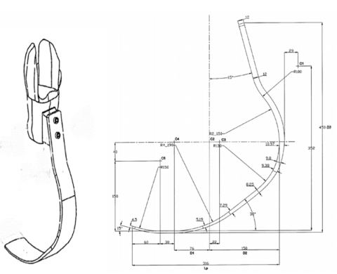
Figure 1. Scheme and dimensions of athletic prosthetic [13]
Since running only uses the front part of the foot, so the blades are suggested to design without a heel [2]. There are many types of sports prosthetics, each with its own set of characteristics. in this study has been used the athletics prosthetic (European patent specification) as indicated in Figure 1.
3.1 Material
The materials used to manufacture the models for this study are as follows:
Ultra High Molecular Weight Polyethylene (UHMWPE) is a semi-crystalline polymer with outstanding mechanical properties, wear resistance, decreased friction, and chemical resistance. It's used in sports equipment, medical prosthetic joints, bullet-proof coats and armour, ropes, and other purposes.
Carbon fibers are the most common type of advanced composite fiber, and they come in a variety of shapes and stiffnesses, depending on the manufacturing process. The ultimate strain or strain to failure is an important attribute of the fiber linked to strength and stiffness since it has a significant impact on the composite laminate's strength.
In polymer matrix composites, glass is the most prevalent fiber. Great strength, low cost, high chemical resistance, and good insulating characteristics are only a few of its benefits. Low elastic modulus, poor adherence to polymers, high specific gravity, abrasion sensitivity (which affects tensile strength), and low fatigue strength are some of the disadvantages.
Perlon stockinet white.
Epoxy resin (PMMA).
Hardening powder (Ottobock health care 617P37).
A polyvinyl alcohol (PVA) (Ottobock health care).
Jepson mold for casting.
And due to the convergence of the mechanical specifications between the carbon fibers and the Ultra and the fact that the latter is less expensive, it was decided to work on the manufacture of a sports prosthetic foot from the Ultra with the reinforcement of the layers with carbon fibers.
The mechanical properties of materials shown in Table 1.
3.2 Equipment
The equipment required to test the laminations in this respect is as follows:
(1) A rectangular positive Jepson mold with dimensions of 10 x 35 x 27 cm3.
(2) A vacuum pressure system with a pump, stands to carry the Jepson mold and pipes.
(3) An accurate digital scale to measure weights of materials used in the manufacturing process.
3.3 Procedure
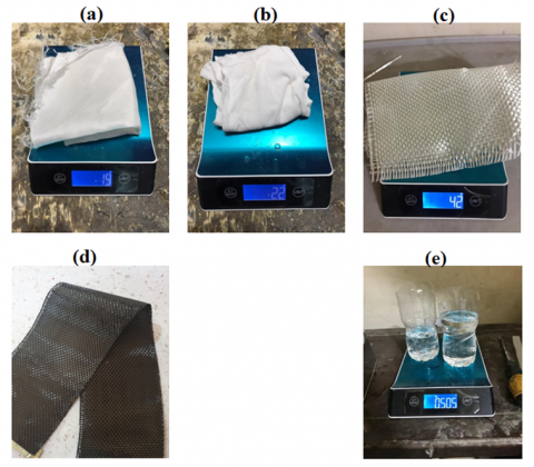
The fibers are cut into required dimensions and weighed with an accurate scale as shown in Figure 2. The gypsum mold is installed on the vacuum system and wrapped with a special (PVA) bag to provide a smooth surface for the composite material and prevent the matrix from sticking to the gypsum mold, and then the layers of composite materials are arranged, where the first layer is placed, and then the matrix material is added by the brush and then the other layer and after that the matrix material and so on until the required number of layers is completed. Finally, the mold is wrapped with the composite material with (PVA) bag and sealed, leaving two holes at the top for pouring the epoxy and the brother at the bottom to pull out the excess epoxy through the tube of the vacuum system. After that, the epoxy material is poured from the upper holes at room temperature and wait for a period of 48 hours to obtain the required Laminate to obtain the required Laminate as shown in Table 2.
Table 1. The mechanical properties of materials [14, 15]
|
Materials |
Tensile Strength (MPa) |
Young Modulus (GPa) |
Density (g/cm³) |
Poisson's Ratio |
|
UHMWPE |
2900 |
114.86 |
0.939 |
0.4 |
|
Perlon |
78 |
3.43 |
1.083 |
0.39 |
|
Carbon fiber |
3800 |
230 |
1.4 |
0.2 |
|
Glass fiber |
3450 |
72.5 |
2.48 |
0.23 |
|
PMMA |
53.8 |
2.5 |
1.19 |
0.38 |
Figure 2. Experimental procedure: (a) Weight of UHMWPE woven fabrics, (b) Weight of Perlon stockinet white, (c) Weight of and woven glass fiber, (d) Woven carbon fiber, and (e) Weight of epoxy resin (PMMA)
Table 2. Types of laminations for laminated composite specimens in this study.
|
Composite lamination system |
Materials Types (matrix and reinforcement) |
Layers' symbol |
|
Laminate 1 |
PMMA + UHMWPE + Carbon fibers + Perlon fibers |
6U+2C |
|
Laminate 2 |
8U+2C |
|
|
Laminate 3 |
12U+4C |
|
|
Laminate 4 |
PMMA + UHMWPE + Glass fibers + Perlon fibers |
6U+2G |
|
Laminate 5 |
8U+2G |
|
|
Laminate 6 |
12U+4G |
To measures the density of composite material can be used ASTM Standards (D 792). Calculated the mass of a specimen in air. It is then immersion in a water, and its apparent mass is measured, as well as its specific gravity (relative density) [16].
$\mathrm{SP}(\mathrm{gr})=\frac{\mathrm{a}}{\mathrm{a}-\mathrm{b}}$ (1)
Density of composite $\left[\rho_{C}\right]=\mathrm{SP}(\mathrm{gr}) \times 997.5$ (2)
where: a = apparent mass of specimen, without wire or sinker, in air, b = apparent mass of specimen (and of sinker, if used) completely immersed and of the wire partially immersed in liquid.
For the purpose of calculating the nine elastic properties of 'laminate (Longitudinal Young’s modulus E1, Transverse Young’s modulus E2, Major Poisson’s ratio ν12, transverse Poisson’s ratio ν23, In-plane shear modulus G12 and Out of plane elastic properties E3, G13, ν13), the weight fraction and fraction volume should be calculated as follows [17]:
$w_{c}=w_{f}+w_{m}$ (3)
$\mathrm{W} f, m=\frac{W_{f, m}}{w_{C}}$ (4)
$V_{m}=\mathrm{W}_{m} \frac{\rho_{C}}{\rho_{m}}$ (5)
where, $w_{f, m}$ the weights of the fiber and matrix, respectively (Kg), Wf, Wm, and Wc are the weights fraction of the fiber, matrix, and composite, respectively and $V_{f}, V_{m}$, and $V_{c}$ are the volume fraction of the fiber, matrix, and composite, respectively.
The mechanical properties of woven fabric differ from the mechanical properties of the unidirectional fiber as follows [18]:
$E_{1}^{\mathrm{W}}=E_{2}^{\mathrm{W}}, \quad G_{13}^{\mathrm{W}}=G_{23}^{\mathrm{W}}, \quad v_{13}^{\mathrm{W}}=v_{23}^{\mathrm{W}}$ (6)
Numerical simulation-based techniques play an important role in engineering research because of their unique characteristics, such as low cost, reliable performance, and a fast procedure. Because of its versatility, advanced techniques in numerical simulation are being implemented more frequently nowadays [19].
This paper also includes numerical simulation, specifically ANSYS ACP Workbench 19, which is a cutting-edge method for dealing with composite materials. ANSYS ACP (pre) 19R3 has the ability to efficiently build reinforcement and its various orientations. The dimensions of the blades were taken from side profiles taken from European patent specification [13] and drawn the geometric by tool ANSYS Geometry, the material constants properties (Young modulus, Poisson's ratios, and shear modulus on the planes) must be defined and manually inserted into the program for the orthotropic component.
5.1 Mesh sizing
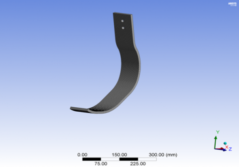
Divided the foot into sub-elements by tool Mesh, so that when the sub elements are a lot, the results are more accurate., in this work the numbers of nodes 7185 and the elements 6915 as shown in (Figure 3).
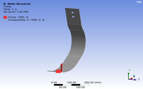
Force vectors with a combined magnitude approximately to 2.5-3 times body weight [20] which will be approximately 1500 N, uniformly distributed on the lower edge, the blade needed to be supported by drilling two holes in the top to simulate the relation to the body (Figure 4).
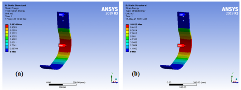
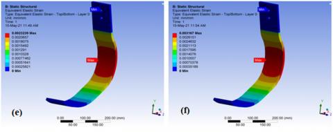
Some tests were carried out on the prosthetic to demonstrate how it dealt with the application of loads, as well as how Equivalent Elastic Strain, Equivalent Stress, the energy is stored was measured, and the Maximum foot deflection is the most realistic of others variables to choose the athletic prosthetic, the athlete's foot deformation showed that the design recompense for the load. The Static structural subcategory of ANSYS 19R ACP (pre) was used to measure each of these values.
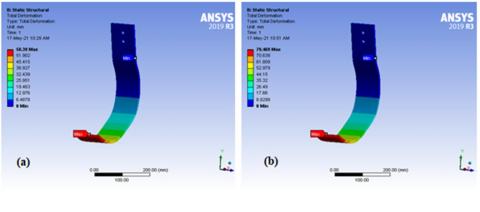
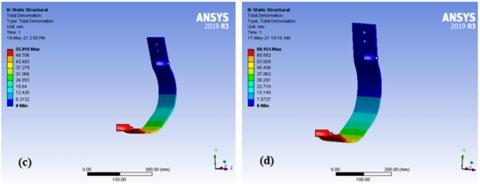
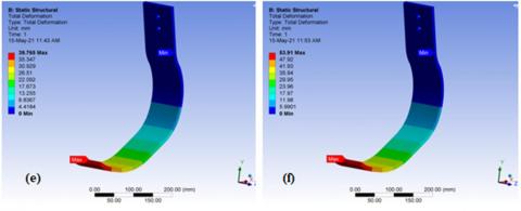
Figure 5(a, c and e) shows total deformation athletic prosthetic when adding woven carbon fiber to the layers of UHMWPE. Figure 5 (b, d and f) shows total deformation athletic prosthetic when adding woven glass fiber to the layers of UHMWPE.
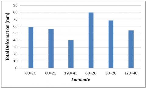
It has been shown that when adding carbon fibers to the UHMWPE layers, it improves the performance of the sports artificial foot in terms of deformation compared to the addition of glass fibers, as shown in Table 3 under the same boundary conditions. Where there was a decrease in the amount of deformation by 26% between the laminate 1 and laminate 4, as well as between the laminate 3 and laminate 6, and the amount of deformation also decreased by 17% between the laminate 2 and laminate 5 as shown in Figure 6.
Figure 3. Mesh sizing
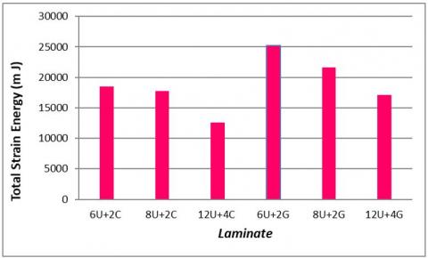
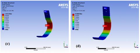
The results also show that there was an improvement in performance when the number of classes was doubled, as the rate of improvement between laminate 1 and laminate 3 was 31%, and between the laminate 4 and laminate 6strata by 32%. A decrease in the energy stored in the athletic prosthetic foot was observed when the stiffness of the composite material increased, as shown in Figures 7 to 8. According to the law of stored energy, the higher the stiffness, the lower the deflection (the less work done), and thus the stored energy decreases (4).
The results also show that there was an improvement in performance when the number of classes was doubled, as the rate of improvement between laminate 1 and laminate 3 was 31%, and between the laminate 4 and laminate 6 strata by 32%. A decrease in the energy stored in the athletic prosthetic foot was observed when the stiffness of the composite material increased, as shown in Figures 7 to 8. According to the law of stored energy, the higher the stiffness, the lower the deflection (the less work done), and thus the stored energy decreases.
Figure 4. Force vectors
Figure 5. Total Deformation of (a) laminate 1, (b) laminate 4, (c) laminate 2, (d) laminate 5, (e) laminate 3, and (f) laminate 6
Figure 6. Total Deformation of laminate
Figure 7. Strain energy of laminate
Table 3. The mechanical properties of laminate
|
Composite lamination system |
Deformation (mm) |
Equivalent Stress (Mpa) |
Equivalent Elastic Strain |
total strain energy (mJ) |
|
Laminate 1 |
58.39 |
144.7 |
0.0033 |
18503 |
|
Laminate 2 |
55.92 |
144.84 |
0.0032 |
17720 |
|
Laminate 3 |
39.765 |
145.83 |
0.0023 |
12601 |
|
Laminate 4 |
79.469 |
145.9 |
0.0046 |
25183 |
|
Laminate 5 |
68.154 |
146.18 |
0.0039 |
21598 |
|
Laminate 6 |
53.91 |
146.53 |
0.0036 |
17084 |
Figure 8. Strain energy of: (a) laminate 3, (b) laminate 4, (c) laminate 2, (d) laminate 5, (e) laminate 3, and (f) laminate 6
This study looks at how prosthetic limbs, specifically the athletic prosthetic foot, are used. The current study concentrated on the manufacturing and production properties of a sample athletic prosthetic foot made of composite materials based on a polymethyl methacrylate resin (PMMA) reinforced with various fibers (UHMWPE, Perlon, Carbon fiber, and Glass fiber). Manufacture six laminate and it has been observed that when a number of carbons fib fiber er layers are added to UHMWPE, it has a better effect in deformation than the addition of the glass fiber 26% improvement. Also, the findings show there is an improvement in performance when the number of classes is doubled. Besides, the improvement rate was 31% as a result of using carbon fibers, while it reached 32% when adding glass fibers under the same conditions.
[1] Nolan, L. (2008). Carbon fibre prostheses and running in amputees: A review. Foot and Ankle Surgery, 14(3): 125-129. https://doi.org/10.1016/j.fas.2008.05.007
[2] Rahman, M., Bennett, T., Glisson, D., Beckley, D., Khan, J. (2014). Finite element analysis of prosthetic running blades using different composite materials to optimize performance. Proceedings of the ASME 2014 International Mechanical Engineering Congress and Exposition (IMECE 2014), Montreal, Quebec, Canada. https://doi.org/10.1115/IMECE2014-37293
[3] Shasmin, H.N., Osman, N.A., Latif, L.A. (2008). Comparison between biomechanical characteristics of stainless steel and bamboo pylons: A preliminary study. In 4th Kuala Lumpur International Conference on Biomedical Engineering 2008, 21(1): 851-853. https://doi.org/10.1007/978-3-540-69139-6-210
[4] LeMoyne, R. (2016). Passive transtibial prosthesis and associated prosthetic components. In Advances for Prosthetic Technology, Springer, Tokyo, pp. 59-68. https://doi.org/10.1007/978-4-431-55816-3_5
[5] Nielsen, D.H., Shurr, D.G., Golden, J.C., Meier, K. (1988). Comparison of energy cost and gait efficiency during ambulation in below-knee amputees using different prosthetic feet—a preliminary report. JPO: Journal of Prosthetics and Orthotics, 8: 95-100.
[6] Patarata, V.S. (2017). Structural simulation of 3D limb prostheses using meshless methods. https://repositorio-aberto.up.pt/handle/10216/107686.
[7] Sun, J.M., Voglewede, P.A. (2011). Controller implementation of a powered transtibial prosthetic device. In International Design Engineering Technical Conferences and Computers and Information in Engineering Conference, 54839: 597-603. https://doi.org/10.1115/DETC2011-47957
[8] Kumar, P.K., Charan, M., Kanagaraj, S. (2017). Trends and challenges in lower limb prosthesis. IEEE Potentials, 36(1): 19-23. https://doi.org/10.1109/MPOT.2016.2614756
[9] Hawkins, J. (2015). The Dynamic characterisation of ESR prosthetic running feet: an investigation of the key parameters affecting their performance. Doctoral dissertation, Bournemouth University.
[10] Rigney, S.M., Simmons, A., Kark, L. (2017). Mechanical characterization and comparison of energy storage and return prostheses. Medical Engineering & Physics, 41: 90-96. https://doi.org/10.1016/j.medengphy.2017.01.003
[11] Bhagavathiyappan, S., Balamurugan, M., Rajamanickam, M., Vijayanandh, R., Kumar, G.R., Kumar, M.S. (2020). Comparative computational impact analysis of multi-layer composite materials. In AIP Conference Proceedings, 2270(1): 040007. https://doi.org/10.1063/5.0019380
[12] Alizadeh, Y. (2020). Design and Structural Analysis of Composite Prosthetic Running Blades for Athletes.
[13] Bonacini, D. (2011). Method for positioning a bracket-fixable running foot for lower limb prosthesis, European Patent Office 2011.
[14] Callister, W.D., Rethwisch, D.G. (2011). Materials Science and Engineering (Vol. 5, pp. 344-348). NY: John Wiley & Sons.
[15] Abed, M.S., Ahmed, P.S., Oleiwi, J.K., Fadhil, B.M. (2020). Low velocity impact of Kevlar and ultra high molecular weight polyethylene (UHMWPE) reinforced epoxy composites. Multidiscipline Modeling in Materials and Structures, 16(6): 1617-1630. https://doi.org/10.1108/MMMS-09-2019-0164
[16] ASTM D 792-20. (2020). Standard Test Methods for Density and Specific Gravity (Relative Density) of Plastics. Annu. B. ASTM Stand., vol. 08.01, pp. 1-6.
[17] A.K. Kaw, Mechanics of Composite Materials 2nd ed. Boca Raton, London, New York: Taylor & Francis Group, 2006.
[18] Akkerman, R. (2005). Laminate mechanics for balanced woven fabrics. Composites Part B: Engineering, 37(2-3): 108-116. https://doi.org/10.1016/j.compositesb.2005.08.004
[19] Vijayanandh, R., Kumar, G.R., Kumar, M.S., Karthick, M., Ramganesh, T. (2016). Fatigue life estimation of aircraft engine compressor with suitable material selection (Analytical approach for compressor lifetime). In 2016 10th International Conference on Intelligent Systems and Control (ISCO), pp. 1-5, Coimbatore, India. https://doi.org/10.1109/ISCO.2016.7727055
[20] Mitu, L.G. (2014). Methods and techniques for bio-system's materials behaviour analysis. Doctoral Dissertation. https://dialnet.unirioja.es/servlet/tesis?codigo=86961.