Faiza Khalid* | Manaa Rabah | Saad Salah | Ameddah Hacene
© 2021 IIETA. This article is published by IIETA and is licensed under the CC BY 4.0 license (http://creativecommons.org/licenses/by/4.0/).
OPEN ACCESS
The turbine blades are subjected to high operating temperatures and high centrifugal tensile stress due to rotational speeds. The maximum temperature at the inlet of the turbine is currently limited by the resistance of the materials used for the blades. The present paper is focused on the thermo-mechanical behavior of the blade in composite materials with reinforced mast under two different types of loading. The material studied in this work is a composite material, the selected matrix is a technical ceramic which is alumina (aluminum oxide Al2O3) and the reinforcement is carried out by short fibers of high modulus carbon to optimize a percentage of 40% carbon and 60% of ceramics. The simulation was performed numerically by Ansys (Workbench 16.0) software. The comparative analysis was conducted to determine displacements, strains and Von Mises stress of composite material and then compared to other materials such as Titanium Alloy, Stainless Steel Alloy, and Aluminum 2024 Alloy. The results were compared in order to select the material with the best performance in terms of rigidity under thermo-mechanical stresses. While comparing these materials, it is found that composite material is better suited for high temperature applications. On evaluating the graphs drawn for, strains and displacements, the blade in composite materials reinforced with mast is considered as optimum.
alumina, blade, thermo-mechanical behavior, Ansys, short fibers, high modulus carbon, speeds
Nowadays, the improvement of modern turbo machines efficiency, especially gas turbines, is achieved mainly by increasing their temperature level in the combustion chamber. The maximum temperature at the inlet of the turbine is currently limited by the resistance of the materials used for the impeller blades. The deterioration of the thermal barrier systems occurs by peeling the ceramic layer. The bared metal is then exposed to dangerously hot gases from the combustion chamber. So far, numerous studies have been conducted on the materials of gas turbine blades [1]. Uses ANSYS 16 for static, thermal and modal analysis of the distribution of thermal stress and temperature in the gas turbine blade of different titanium alloy, stainless steel and aluminum 2024 materials [2]. A study was carried out by other authors [3] on thermo-mechanical fatigue behavior for material Inconel 738. The work is mainly focused on the resistance of solid turbine blades to investigate the balanced thermal and structural performance of the blade for Inconel 738 materials and Inconel U500. A coupled thermo-mechanical simulation of a coated vane is used to model the flaking of the thermal barrier that occurs under the service conditions of the blade [4]. Another work [5] An attempt to analyze the gas turbine blade by comparing the Hastelloy X material to Nimonic alloy 80A and Inconel 625. Alain KÖSTER [6] has carried out a work on Modeling of Super was paloy damage in thermal fatigue. Whereas M. Pierre-Yvan THERY [7] has conducted a work on the experimental and modeling scaling realized on two particular thermal barrier systems and a comparison was proposed. Then Antoine MILLECAMPS [8] has carried out numerical simulations for the study of blades dynamics and the influence of the contact, the wear and the thermo-mechanical forces on the vibratory behavior [9]. A study was carried out by other authors [10] on thermo-mechanical fatigue behavior for two different materials (Inconel 718 and titanium T6). The work is mainly focused on the resistance of solid turbine blades to investigate the balanced thermal and structural performance of the blade for N 155 materials, X nickel base super alloy and Inconel 625. Finally [11] has studied a new thermal insulation ceramic that can operate at higher temperatures and based on partially stabilized zirconia with uterus. This is a logical continuation of the work conducted for several years at ONERA on the search for new ceramic compositions. It is from these considerations that the study of thermo-mechanical behavior on a composite material is initiated. The objective of optimizing such a composite material is to design a fin which supports the bulk of the thermo-mechanical loading. The objective of this work is to evaluate the thermo-mechanical behavior of fins in composite materials with reinforcement in short fiber (mast) high modulus carbon.
To observe the thermo-mechanical behavior of blade in composite material, in this study, we will calculate the displacements and the deformations of the blade in composite material with random orientation and super-alloy. The characteristics of the gas turbine blade manufacturing materials are listed in Table 1 and 2.
Table 1. Mechanical and thermal characteristics of super alloys [1]
|
Materials |
Titanium Alloy |
Stainless Steel Alloy |
Aluminum 2024 Alloy |
|
Density [Kg/m3] |
4700 |
8025 |
2750 |
|
Young’s modulus [GPa] |
205 |
200 |
73 |
|
Poisson’s ratio |
0.33 |
0.30 |
0.33 |
|
Yield strength [MPa] |
1000 |
1050 |
470 |
|
Coefficient of thermal expansion 10-6℃ |
8.8 |
14.5 |
23.3 |
Table 2. Mechanical and thermal characteristics of high modulus carbon (HM) and alumina [12]
|
Materials |
Carbon (HM) |
Alumina (Al2O3) |
|
Density [Kg/m3] |
1800 |
3700 |
|
Young’s modulus [GPa] |
390 |
380 |
|
Poisson’s ratio |
0.35 |
0.25 |
|
Yield strength [MPa] |
2500 |
1400 |
|
Coefficient of thermal expansion $\left[10^{-6}\left({ }^{\circ} \mathrm{C}^{-1}\right)\right]$ |
0.8 |
8 |
3.1 Mechanical characteristics
All equations of mechanical characteristics are given by Gay [12] and are recalled here for more clearness.
Longitudinal modulus of elasticity EL is given by the following equation:
$\mathrm{E}_{\mathrm{L}}=\mathrm{E}_{\mathrm{f}} V_{\mathrm{f}}+\mathrm{E}_{\mathrm{m}}\left(1-\mathrm{V}_{\mathrm{f}}\right)$ (1)
Transverse modulus of elasticity ET is expressed as follows:
$\mathrm{E}_{\mathrm{T}}=\frac{\mathrm{E}_{\mathrm{m}} \mathrm{E}_{\mathrm{f}}}{\mathrm{E}_{\mathrm{f}} \mathrm{V}_{\mathrm{m}}+\mathrm{E}_{\mathrm{m}} \mathrm{V}_{\mathrm{f}}}$ (2)
Then Poisson’s ratio νL and $v_{\mathrm{T}}$ is written as:
$\mu_{\mathrm{L}}=v_{\mathrm{f}} V_{\mathrm{m}}+v_{\mathrm{m}}\left(1-V_{\mathrm{f}}\right)$ (3)
$\mu_{\mathrm{T}}=\mu_{\mathrm{L}} \frac{\mathrm{E}_{\mathrm{T}}}{\mathrm{E}_{\mathrm{L}}}$ (4)
Finally the Longitudinal shear modulus GL and Transverse shear modulus GT expressed as follows:
$\mathrm{G}_{\mathrm{L}}=\frac{\mathrm{G}_{\mathrm{m}} \mathrm{G}_{\mathrm{f}}}{\mathrm{G}_{\mathrm{f}} \mathrm{V}_{\mathrm{m}}+\mathrm{G}_{\mathrm{m}} \mathrm{V}_{\mathrm{f}}}$ (5)
$G_{T}=\frac{E_{T}}{2\left(1+v_{T}\right)}$ (6)
3.2 Thermal characteristics
Thermal characteristics are explained and resumed by Mallick [13].
The longitudinal thermal expansion $\alpha_{\mathrm{L}} \text { and }$ Transverse thermal expansion are written as:
$\alpha_{\mathrm{L}}=\frac{\left(1-\mathrm{V}_{\mathrm{f}}\right) \alpha_{\mathrm{m}} \mathrm{E}_{\mathrm{m}}+\mathrm{V}_{\mathrm{f}} \alpha_{\mathrm{f}} \mathrm{E}_{\mathrm{f}}}{\left(1-\mathrm{V}_{\mathrm{f}}\right) \mathrm{E}_{\mathrm{m}}+\mathrm{V}_{\mathrm{f}} \mathrm{E}_{\mathrm{f}}}$ (7)
$\alpha_{\mathrm{T}}=\left(1-\mathrm{V}_{\mathrm{f}}\right) \alpha_{\mathrm{m}}+\mathrm{V}_{\mathrm{f}} \alpha_{\mathrm{f}}+\left(\alpha_{\mathrm{f}}-\alpha_{\mathrm{m}}\right) \frac{\mathrm{v}_{\mathrm{f}} \mathrm{E}_{\mathrm{m}}-\mathrm{v}_{\mathrm{m}} \mathrm{E}_{\mathrm{f}}}{\frac{\mathrm{E}_{\mathrm{m}}}{\mathrm{V}_{\mathrm{f}}}+\frac{\mathrm{E}_{\mathrm{f}}}{1-\mathrm{V}_{\mathrm{f}}}}$ (8)
3.3 Mechanical properties of the composite with mast reinforcement [14]
In this case the corresponding transformed reduced rigidity will be examined by:
$\widetilde{Q}_{i j}=\frac{\int_{0}^{2 \pi}\left(\bar{Q}_{i j}\right) \partial \theta}{\int_{0}^{2 \pi} \partial \theta}$ (9)
And the elastic modules of the mast layer are:
$\mathrm{E}_{\mathrm{mât}}=\frac{\left(\mathrm{V}_{1}-\mathrm{V}_{4}\right)\left(\mathrm{V}_{1}+\mathrm{V}_{4}\right)}{\mathrm{V}_{1}}$
$v_{\text {mât }}=\frac{V_{4}}{V_{1}}$ (10)
$G_{\text {mât }}=\frac{V_{1}-V_{4}}{2}$
With the expressions of $\mathrm{V}_{\mathrm{i}}$ are:
$V_{1}=\frac{1}{8}\left(3 Q_{11}+3 Q_{22}+3 Q_{12}+4 Q_{66}\right)$;
$V_{2}=\frac{1}{2}\left(Q_{11}-Q_{22}\right)$; (11)
$V_{3}=\frac{1}{8}\left(Q_{11}+Q_{22}-2 Q_{12}\right)$;
$\mathrm{V}_{4}=\frac{1}{8}\left(\mathrm{Q}_{11}+\mathrm{Q}_{22}+6 \mathrm{Q}_{12}-4 \mathrm{Q}_{66}\right)$
In our study we propose to realize a gas turbine blade in composite materials with reinforced mast. The material studied is a composite material, the selected matrix is a technical ceramic which is an alumina (aluminum oxide Al2O3) and the reinforcement is carried out by short fibers of carbon HM to optimize a percentage of 40% carbon and 60% of ceramics.
5.1 By the law of mixtures
The characteristics of composite material studied are presented below in Tables 3 and 4, respectively.
Table 3. Mechanical and thermal characteristics of the material studied
|
Young’s Modulus [GPa] |
EL |
384 |
|
ET |
383.94 |
|
|
Poisson’s ratio |
$\boldsymbol{v}_{\mathrm{L}}$ |
0.29 |
|
$\mathbf{v}_{\mathrm{T}}$ |
0.29 |
|
|
Shear modulus [GPa] |
$\mathbf{G}_{\mathrm{L}}$ |
148.88 |
|
$\mathbf{G}_{\mathrm{T}}$ |
148.82 |
|
|
thermal expansion [ $\left[10^{-6}\left({ }^{\circ} \mathrm{C}^{-1}\right)\right]$ ] |
$\alpha_{\mathrm{L}}$ |
5.075 |
|
$\alpha_{\mathrm{T}}$ |
4.96 |
5.2 By the law of the behavior of the composite with reinforcement mast
Table 4. Mechanical properties of the mast reinforced composite
|
$\text { Young's Modulus }$ $\mathbf{E}_{\mathbf{m â t}}[\mathrm{GPa}]$ |
$\text { Poisson's ratio }$ $\mathbf{v}_{\mathbf{m â t}}$ |
$\text { Shear modulus }$ $\mathbf{G}_{\mathbf{m â t}}[\mathrm{GPa}]$ |
|
400.44 |
0.2797 |
156.45 |
6.1 Gas turbine blade modeling
Three-dimensional model of the gas turbine blade is first modeled using the solid works software as described [1]. The meshing and analysis is done using ANSYS software by converting the design in IGS software and imported to Ansys for finding the stresses in the blade shown in Figure 1.
Figure 1. Gas turbine blade model
6.2 Model analysis of a gas turbine blade
It is proposed to study the mechanical behavior of a blade in composite material; thus, the analysis is carried out to determine the displacements and strains of the blade.
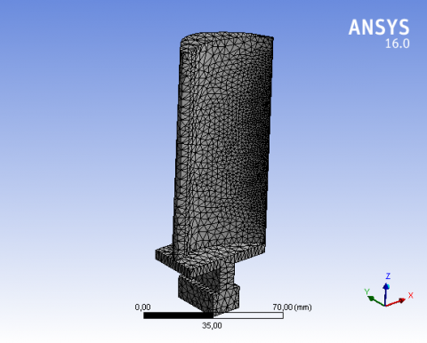
Boundary conditions are applied to the blade root, as applied by [1]. Three different types of loading were applied to the model. Fa=3.82 N, Ft=248.199 N, Fc=38038.73 N. In the solution part of the ANSYS, the blade forces are applied on the node located at the centroid of the blade. The blade is meshed with tetrahedron elements. The tetrahedral element is the simplest tessellated shape and is able to model arbitrary 3-D geometric structures. It is also well suited for automatic mesh generation. The mesh composed of 10987 elements and 20950 nodes. as shown in Figure 2.
Figure 2. Finite element model of turbine blade
Due to the absence of the experimental study for that is why we compared the results obtained with the results obtained by Ahmed [1]. Structural analysis was carried out by applying the same limit conditions and mechanical forces selected materials for blade for validation. The desired comparison was made on the materials such as Aluminum 2024 Alloy, Stainless Steel Alloy and Titanium Alloy.
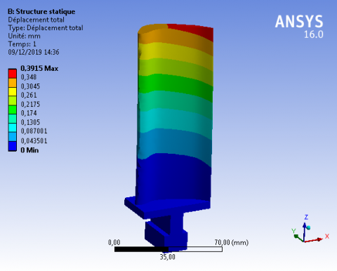
Figure 3 Show the displacement of the blade in the Titanium Alloy. the maximum displacement with a magnitude of 0.3915 mm.
Figure 3. Resultant displacements of titanium alloy
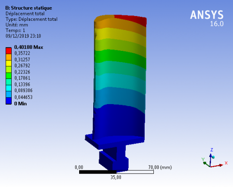
Figure 4. Resultant displacements of stainless steel alloy
Figure 4 shows the displacement of the blade in the Stainless-Steel Alloy. The maximum displacement with a magnitude of 0.40188 mm.
Figure 5. Resultant displacements of aluminum 2024 alloy
Figure 5 Show the displacement of the blade in the Aluminum 2024 Alloy. the maximum displacement with a magnitude of 1.0994 mm.
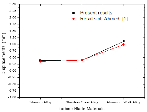
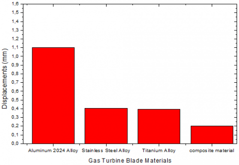
Figure 6. Turbine blade materials as a function of displacements
To confirm the reliability of our numerical study, we compared the results of our attempt with the previous results.
The results obtained and published by Ahmed [1] are used to illustrate the validity of the attempt. Figure 6 Show the comparison between the displacements results for the (present numerical study and numerical studied by Ahmed [1]. The results of displacement allowed us to note the conformity of the results given by the present numerical study and those obtained by Ahmed [1]. It should be noted that the precision of the numerical study gives very acceptable results.
This work deals with modeling and analysis of the gas turbine blade were analyzed in ANSYS (Workbench 16.0) software. Different materials such as, Titanium Alloy, Stainless Steel Alloy, and Aluminum 2024 Alloy were compared to composite material.
8.1 Static analysis of blade
In this case, we will study the static analysis of the blade in the composite material under the given mechanical loading and boundary conditions. The results of the analysis are discussed below.
Figure 7. Distribution of the displacements of a blade in composite material
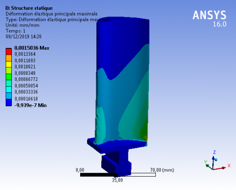
Figure 8. Distribution of the principal elastic strains of a blade in composite material
Figure 7 Show the displacement of the blade in the composite material. the maximum displacement with a magnitude of 0.20088 mm at the ends of the blade and the minimum displacement at the foot of the blade.
Figure 8 shows the maximum principal strains of 0.0015036 occur at the root section and on the pressure side of the gas turbine blade.
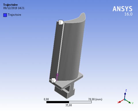
Figure 9. Direction of path
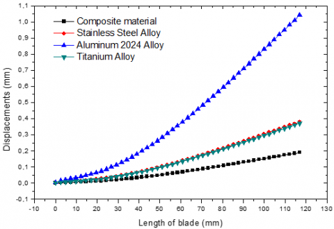
Figure 10. Comparing the displacements (for 4 materials) according to the length of the blade
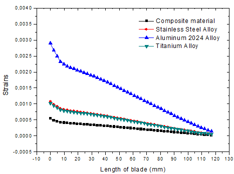
Figure 11. Comparing the strains (for 4 materials) according to the length of the blade
Figure 12. Turbine blade materials according to displacements
The results giving displacements and strains of blade in different materials we will plot according to the continuous path between point 1 and point 2 shown on the Figure 9.
Figure 10 shows the evolution of the displacements as a function of the blade length. It can be noted that the displacement of the composite blade gives better results in comparison with other materials. It is also observed that the maximum value of the displacement is localized in the blade of Aluminum 2024 Alloy material at 1.0416 mm, while the minimum value is found in the composite blade which at 0.19042 mm.
Figure 11 shows the evolution of the strains as a function of the blade length. It can be noted that the strains of the composite blade give better results in comparison with other materials. It is also observed that the maximum value of the strain is localized in the blade of Aluminum 2024 Alloy material at 0.0028978 while the minimum value is found in the composite blade which at 0.0004139.
Figure 12 shows the variation of displacements distribution for different materials of turbine blade. It is noted that the displacements are varying as the radial distance increases, the maximum value for Aluminum 2024 Alloy and the minimum value for composite.
8.2 Thermomechanical analysis of turbine blade
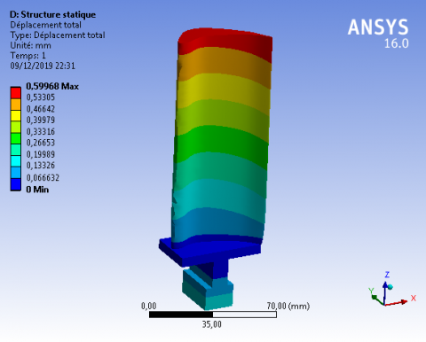
Figure 13. Distribution of the displacements of a blade in composite material
Figure 14. Distribution of the principal elastic strains of a blade in composite material
In this case, we will study the thermomechanical behavior of the blade under the same loading conditions and boundaries previously defined. under the influence of temperature T= 800℃.
A summary of the results obtained from the thermal analysis of the same previous materials.
Figure 13 shows displacements produced in the turbine blade due to action of centrifugal forces and temperature. It is observed that the maximum deformation of 0.59968 mm occurs at the tip section of turbine blade material and the minimum occurs at the root section. There was no evidence of rubbing between tip of the turbine blade and casing indicating elongation is within the limit.
Figure 14 shows the Strain distribution in the turbine blade due to action of centrifugal forces and temperature. It is observed that the maximum strain of 0.0099824 occurs at the root section and on the pressure side of gas turbine blade. Minimum stress occurs at the tip section pressure side of gas turbine blade.
Figure 15. Comparing the displacements (for 4 materials) according to the length of the blade
Figure 15 shows the evolution of the displacements as a function of the blade length. It can be noted that the displacement of the composite blade gives better results in comparison with other materials. It is also observed that the maximum value of the displacement is localized in the blade of Aluminum 2024 Alloy material at 2,7773 mm, while the minimum value is found in the composite blade which at 0,58044 mm.
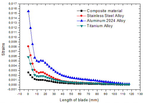
Figure 16. Comparing the principal elastic strains (for 4 materials) according to the length of the blade
Figure 16 shows the evolution of the strains as a function of the blade length. It can be noted that the strains of the composite blade give better results in comparison with other materials. It is also observed that the maximum value of the strain is localized in the blade of Aluminum 2024 Alloy material at 0.015668, while the minimum value is found in the composite blade which at 0.0025769.
8.3 Analysis of turbine blade at various speeds
In this case, we will compare the same materials under temperature (T=800°C) with the change in the rotational speed value with three values: 4000 rpm, 6000 rpm, and 9000 rpm. Results on displacement and strain are shown in Tables 5, 6 respectively.
Table 5. Displacements of turbine blades made of different materials at various speeds
|
Materials |
Displacements (mm) |
||
|
4000(RPM) |
6000(RPM) |
9000(RPM) |
|
|
Composite material |
0.52029 |
0.52041 |
0.52071 |
|
Titanium Alloy |
0.91156 |
0.91195 |
0.91291 |
|
Stainless Steel Alloy |
0.4927 |
1.4934 |
1.4951 |
|
Aluminum 2024 Alloy |
2.4133 |
2.4139 |
2.4153 |
Table 6. Strains of turbine blades made of different materials at various speeds
|
Materials |
Strains (mm) |
||
|
4000(RPM) |
6000(RPM) |
9000(RPM) |
|
|
Composite material |
0.01069 |
0.010684 |
0.01067 |
|
Titanium Alloy |
0.020138 |
0.020115 |
0.020062 |
|
Stainless Steel Alloy |
0.031627 |
0.03159 |
0.031508 |
|
Aluminum 2024 Alloy |
0.053339 |
0.053301 |
0.053215 |
The results giving displacements and strains of blade in different materials shown in the Figures 17, 18.
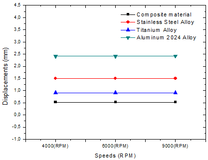
Figure 17. Total displacements induced in turbine blades made of different materials at various speeds
Figure 18. Strains induced in turbine blades made of different materials at various speeds
The Thermomechanical analysis of turbine Blades with different rotational speeds 4000, 6000 and 9000 rpm’s by specifying structural and thermal loads with the objective of know the preferred material for the best performance. Based on the results obtained from the Ansys software the graphs, Figure 17 (Total displacement vs Rotation), Figure 18 (Strain vs Rotation) were plotted. The displacement and strains are proportionally increasing with an increase in rotation (RPM). this study it is concluded that the composite material should be used as turbine blade materials in the case of fixed or variable velocity because the displacement and strain is the minimum in the materials used in the comparison.
The choice of optimized composite material, significantly reduces the deformations along the fin and therefore locally reduces micro cracking causing wear flaking. In order to achieve the desired results, we completed the establishment of a research protocol in a predefined order:
The authors like to thank the Algerian general direction of research (DGRSDT) for their financial support and the head of mechanical engineering laboratory at the University of Biskra for technical assistance.
|
E |
Young’s modulus of matrix, GPa |
|
Ef |
Young’s modulus of fiber, GPa |
|
EL |
Elastic modulus in the longitudinal direction, GPa |
|
Em |
Young’s modulus of matrix, GPa |
|
Emàt |
Young’s modulus of the mast reinforcement, GPa |
|
ET |
Elastic modulus in the transverse direction, GPa |
|
Fa |
Axial force N |
|
Fc |
Centrifugal force N |
|
Ft |
Tangential force N |
|
GL |
Shear modulus in longitudinal direction, GPa |
|
$G_{\text {mât }}$ |
Shear modulus of the mast reinforcement |
|
GT |
Shear modulus transverse direction, GPa |
|
L |
Length mm |
|
Vf |
Fiber volume fraction |
|
Vm |
Matrix volume fraction |
|
α |
Coefficient of thermal expansion, $10^{-6}\left({ }^{\circ} \mathrm{C}^{-1}\right)$ |
|
αL |
Thermal expansion in the longitudinal direction, $10^{-6}\left({ }^{\circ} \mathrm{C}^{-1}\right)$ |
|
αT |
thermal expansion in the Transverse direction, $10^{-6}\left({ }^{\circ} \mathrm{C}^{-1}\right)$ |
|
μ |
Poisson’s ratio |
|
μL |
Poisson’s ratio in the longitudinal direction |
|
$\mu_{\mathrm{mât}}$ |
Poisson’sratio of the mast reinforcement |
|
μT |
Poisson’s ratio in the Transverse direction |
|
$\rho$ |
Density [Kg/m3] |
|
$\delta$ |
Yield strength |
[1] Jabbar, A.A., Rai, A.K., Reedy, P.R., Dakhil, M.H. (2014). Design and analysis of gas turbine rotor blade using finite element method. International Journal of Mechanical and Production, 4(1): 91-112.
[2] Rani, S., Agrawal, A.K., Rastogi, V. (2017). Failure analysis of a first stage IN738 gas turbine blade tip cracking in a thermal power plant. Case Studies in Engineering Failure Analysis, 8: 1-10. https://doi.org/10.1016/j.csefa.2016.11.002
[3] Ikpe, A., Oghenefejiro, E.O., Ariavie, G. (2018). Thermo-structural analysis of first stage gas turbine rotor blade materials for optimum service performance. International Journal of Engineering and Applied Sciences, 10(2): 118-130. https://doi.org/10.24107/ijeas.447650
[4] Rakotomalala, N. (2014). Simulation numérique de l’écaillage des barrières thermiques avec couplage thermo-mécanique (Doctoral dissertation, Paris, ENMP).
[5] Gurajarapu, N., Rao, V.N.B., Kumar, I.N. (2014). Selection of a suitable material and failure investigation on a turbine blade of marine gas turbine engine using reverse engineering and FEA techniques. International Journal of u-and e-Service, Science and Technology, 7(6): 297-308. https://doi.org/10.14257/ijunesst.2014.7.6.26
[6] Köster, A. (1997). Fatigue thermique d'un alliage pour aubes de turbopompe astronautique: le Superwaspaloy (Doctoral dissertation, Ecole Nationale Supérieure des Mines de Paris). https://www.researchgate.net/publication/46572302
[7] Théry, P.Y. (2007). Adhérence de barrières thermiques pour aube de turbine avec couche de liaison β-(Ni, Pt) Al ou β-NiAl (Zr) (Doctoral dissertation, Université Joseph-Fourier-Grenoble I). https://tel.archives-ouvertes.fr/tel-00258692
[8] Millecamps, A. (2010). Interaction aube-carter: contribution de l’usure de l’abradable et de la thermomécanique sur la dynamique d’aube (Doctoral dissertation, Lille 1). https://tel.archives-ouvertes.fr/tel-01200536
[9] Prasad, R.D.V., Raju, G.N., Rao, M.S., Rao, N.V. (2013). Steady state thermal & structural analysis of gas turbine blade cooling system. International Journal of Engineering Research & Technology (IJERT), 2(1).
[10] Krishnakanth, P.V., Raju, G.N., Prasad, R.D.V., Saisrinu, R. (2013). Structural and thermal analysis of gas turbine blade by using FEM. International Journal of Scientific Research Engineering and Technology, 2(2): 60-65.
[11] Prevost, M.A. (2007). Etude de nouvelles céramiques pour barrière thermique (Doctoral dissertation, Université Pierre et Marie Curie-Paris VI). https://tel.archives-ouvertes.fr/tel-00809130
[12] Gay, D. (2005). Matériaux composites. 5e édition.
[13] Mallick, P.K. (2007). Fiber-Reinforced Composites: Materials, Manufacturing, and Design. CRC Press. http://dx.doi.org/10.1201/9781420005981
[14] Berthelot, J.M. (2010). Mécanique des matériaux et structures composites. Institut Supérieur des Matériaux et Mécaniques Avancés.