Samir Deghboudj* | Wafia Boukhedena | Hamid Satha
© 2020 IIETA. This article is published by IIETA and is licensed under the CC BY 4.0 license (http://creativecommons.org/licenses/by/4.0/).
OPEN ACCESS
The present work aims to carry out modal analysis of orthotropic thin rectangular plate to determine its natural frequencies and mode shapes by using analytical method based on Rayleigh-Ritz energy approach. To demonstrate the accuracy of this approach, the same plate is discritisated and analyzed using the finite element method. The natural and angular frequencies were computed and determined analytically and numerically by using ABAQUS finite element code. The convergency and accuracy of the numerical solution was examined. The effects of geometrical parameters and boundary conditions on vibrations are investigated. The results obtained showed a very good agreement between the analytical approach and the numerical simulations. Also, the paper presents simulations results of testing of the plate with passive vibration control.
free vibration, finite element method, frequency parameter, orthotropic plates, modal analysis
Because of their good resistance to shocks and vibrations, composite plates have found widespread applications in various fields of engineering such as aeronautic, marine and automobile industry [1]. As the vibratory movements are at the root of many problems that can lead to the ruin of structures, the knowledge and the understanding of the vibratory behavior of thin plates has become an important and crucial parameter that must be taken into account when designing structural elements.
Many of research have been dedicated to the study of structural vibrations and methods to reduce the resonant amplitudes, including analyses which determine how to modify the structure to avoid coupling resonant frequencies with excitation sources. The study of the free vibration of orthotropic plates increased during the last two decades. There are number of solutions on free vibration of rectangular plates in the natural frequencies with a wide range of support conditions. The most widely known are those of Warburton [2] and Leissa [3]. The work of Warbuton has been extended by Hermon [4] to analyze the free vibration of rectangular orthotropic plates having either clamped or simply supported edges using the Rayleigh method. Grootenhuis, O’Boy, Krylov and Hosseini have proposed an exact solution for free flexural vibration of rectangular thick plates using third order shear deformation plate theory [5, 6]. Ramu and Mohantyb have provided a suitable study on free vibration of rectangular plate structures using finite element method [7]. Werfalli and Karoud have conducted a free vibration analysis of rectangular plates using Galerkin based finite element method [8]. Mama studied and proposed a solution of free harmonic equation of simply supported plates using Galerkin-Valsov method [9].
Hatiegan analyzed by finite element method thin clamped plates of different geometric forms [10]. Pouladkhan have determined different frequencies and shape modes of thin rectangular plates by using modal analysis [11]. Rock and Hinton developed a new finite element to analyze free vibration and transient response of thick and thin plates [12]. Also, Liux and Chen developed a mesh-free method for static and free vibration analyses of thin plates of complicated shape [13]. Zhou investigated the natural vibration of circular and annular thin plates by Hamiltonian approach [14]. Benamar examined the effects of large vibration amplitudes on the mode shapes and natural frequencies of thin isotropic plates [15]. Alfano and Pagnotta performed a suitable approximate relationships, relating the resonance frequencies to the elastic constants of isotropic thin plates [16]. Ritz and Rayleigh-Ritz methods have also been used for vibration analysis of thin rectangular plates. Hanna and Leissa developed an approach based on higher-order shear deformation plate theory of Reddy to analyze free vibration of fully free rectangular plates using Rayleigh–Ritz method [17]. Dozio used a trigonometric Ritz method for general vibration analysis of rectangular Kirchhoff plates [18]. Vescovini used the Ritz method to estimate the free vibration and buckling analysis of highly anisotropic plates [19].
The vibration damping can be achieved by attaching patches elements on to the structure. This allows a convenient method of damping vibrations without adding significant mass and volumetric occupancy, unlike the bulky mechanical dampers. The application of patches for reducing vibrations and structure borne noise has been studied by many researchers in the past few years [20-22]. This paper presents studies made on fundamental flexural frequencies of thin orthotropic rectangular plates by using Rayleigh approximation method and finite element method (FEM). Three types of boundary conditions are investigated (all edges clamped (CCCC), all edges simply supported (SSSS) and two edges clamped, two edges simply supported (SCSC)). A comparison between the results obtained with both methods has been done. Also, the effect of geometrical parameters on natural vibrations of rectangular plates was carried out. The values of frequency parameter of the plate having different (length/width) ratios in case of (a/b³1) were studied. Vibration control of the structure is realized through patches attached to the plate. Simulations and numerical computations of the structure are performed in ABAQUS.
2.1 Theoretical formulations
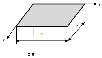
Main used plate theories can be classified into four classes: classical thin plate theory of Kirchhoff (CPT) used in this work [23], first-order shear deformation plate theory of Mindlin (FSDT) [24], higher-order shear deformation plate theory of Reddy (HSDT) [25] and three-dimensional (3-D) elasticity theory [26]. The simplest plate theory (CPT) is based on the assumption that straight lines perpendicular to the mid plane before deformation remain straight and normal to the mid plane after deformation. It is considering a thin homogeneous orthotropic plate of a constant thickness, as shown in Figure 1. Denote the length and width of the plate by a, b. The plate occupies a region given by Eq. (1):
$0 \leq x \leq a \quad 0 \leq y \leq b$ (1)
Figure 1. Typical scheme of the plate
According to the classical thin plate theory of Kirchhoff, in the case of orthotropic plates for which (D16=D26=0), the fundamental relations are written, taking into account the absence of transverse loads (q=0).
$u_{0}=0 \quad, \quad v_{0}=0$ (2)
$\begin{array}{l}
D_{11} \frac{\partial^{4} w_{0}}{\partial x^{4}}+2\left(D_{12}+D_{66}\right) \frac{\partial^{4} w_{0}}{\partial x^{2} \partial y^{2}}+D_{22} \frac{\partial^{4} w_{0}}{\partial y^{4}} \\
+\rho_{s} \frac{\partial^{2} w_{0}}{\partial t^{2}}=I_{x y}\left(\frac{\partial^{4} w_{0}}{\partial x^{2} \partial t^{2}}+\frac{\partial^{4} w_{0}}{\partial Y^{2} \partial t^{2}}\right)
\end{array}$ (3)
In the case where the rotatory inertia terms can be neglected (Ixy=0), equation of motion reduces to:
$\begin{array}{l}
D_{11} \frac{\partial^{4} w_{0}}{\partial x^{4}}+2\left(D_{12}+D_{66}\right) \frac{\partial^{4} w_{0}}{\partial x^{2} \partial y^{2}}+D_{22} \frac{\partial^{4} w_{0}}{\partial y^{4}} \\
+\rho_{s} \frac{\partial^{2} w_{0}}{\partial t^{2}}=0
\end{array}$ (4)
where, Dij are the effective bending and twisting stiffness, w0(x,y) is the deflection, rs and w are the mass density and circular frequency, respectively. To solve the differential Eq. (4), consider a solution of the form:
$w_{0}(x, y, t)=w_{0}(x, y) e^{i \omega t}$ (5)
where, w is the angular frequency of the vibrations, leads, by substituting this expression into Eq. (4) to:
$\begin{array}{l}
D_{11} \frac{\partial^{4} w_{0}}{\partial x^{4}}+2\left(D_{12}+D_{66}\right) \frac{\partial^{4} w_{0}}{\partial x^{2} \partial y^{2}}+D_{22} \frac{\partial^{4} w_{0}}{\partial y^{4}} \\
-\rho_{s} \omega^{2} w_{0}=0
\end{array}$ (6)
In case of simply supported edges, the boundary conditions are given as follow:
Edges x=0 and x=a:
$w_{0}=0, \quad M_{x}=-D_{11} \frac{\partial^{2} w_{0}}{\partial x^{2}}-D_{12} \frac{\partial^{2} w_{0}}{\partial y^{2}}=0$ (7)
Edges y=0 and y=b:
$w_{0}=0, \quad M_{y}=-D_{12} \frac{\partial^{2} w_{0}}{\partial x^{2}}-D_{22} \frac{\partial^{2} w_{0}}{\partial y^{2}}=0$ (8)
And w0(x, y) can be put in the form:
$w_{0}(x, y)=C_{m n} \sin m \pi \frac{x}{a} \sin m \pi \frac{y}{b}$ (9)
Substituting this expression which satisfying the support conditions into Eq. (6) yields:
$\left[\begin{array}{l}
\frac{m^{4} \pi^{4}}{a^{4}} D_{11}+2 \frac{m^{2} n^{2} \pi^{4}}{a^{2} b^{2}}\left(D_{12}+2 D_{66}\right) \\
+\frac{n^{4} \pi^{4}}{b^{4}} D_{22}-\rho_{s} \omega^{2}
\end{array}\right] C_{m n}=0$ (10)
For a nonzero value of Cmn, the expression of the natural frequencies becomes:
$\omega_{m n}=\frac{\pi^{2}}{a^{2}} \sqrt{\frac{1}{\rho_{s}}\left(m^{4} D_{11}+2 m^{2} n^{2} R^{2}\left(D_{12}+2 D_{66}\right)+n^{4} R^{4} D_{22}\right)}$ (11)
The deformed shape of the plate corresponding to the natural pulsation wmn is given by Expression (9). In the case of other boundary conditions, it is not possible to solve Eq. (9) directly; the determination of the natural frequencies and the vibration modes requires then to use approximate methods. Using the Rayleigh-Ritz approach the frequency equation may be derived from the expression of maximum strain energy of bending:
$\begin{array}{l}
U_{d \max }-E_{c \max }= \\
\quad \frac{1}{2} \int_{x=0}^{a} \int_{y=0}^{b}\left[\begin{array}{c}
D_{11}\left(\frac{\partial^{2} w_{0}}{\partial x^{2}}\right)^{2}+2 D_{12} \frac{\partial^{2} w_{0}}{\partial x^{2}} \frac{\partial^{2} w_{0}}{\partial y^{2}} \\
+D_{22}\left(\frac{\partial^{2} w_{0}}{\partial y^{2}}\right)^{2}+4 D_{66}\left(\frac{\partial^{2} w_{0}}{\partial x \partial y}\right)^{2} \\
-\rho_{s} \omega^{2} w_{0}^{2}
\end{array}\right] d x d y
\end{array}$ (12)
The displacement is assumed to be an infinite series of admissible shape functions in the x and y directions.
$w_{0}(x, y)=\sum_{m=1}^{M} \sum_{n=1}^{N} A_{m n} X_{m}(x) Y_{n}(y)$ (13)
where, Xm(x) and Yn(y) are appropriate shape functions along x and y axes that must satisfy the boundary conditions. Amn are the unknown numerical coefficients of the functions. The assumed displacement functions defining the deflection of the plate are given in the form of series functions, as follow [27]:
Clamped (CCCC):
$w_{0}(x, y)=A_{m n}\left(1-\frac{x^{2}}{a^{2}}\right)\left(1-\frac{y^{2}}{b^{2}}\right) x y \sin \left(m \pi \frac{x}{a}\right) \sin \left(n \pi \frac{y}{b}\right)$ (14)
Simply supported (SSSS):
$w_{0}(x, y)=\sum_{m=1}^{M} \Sigma_{n=1}^{N} A_{m n} \sin \left(m \pi \frac{x}{a}\right) \sin \left(n \pi \frac{y}{b}\right)$ (15)
Simply supported - clamped (SCSC):
$w_{0}(x, y)=\left(1-\frac{x^{2}}{a^{2}}\right)\left(1-\frac{y^{2}}{b^{2}}\right) \sum_{m=1}^{M} \Sigma_{n=1}^{N} A_{m n} \sin \left(m \pi \frac{x}{a}\right) \sin \left(n \pi \frac{y}{b}\right)$ (16)
Finally, the Rayleigh approximation of the natural pulsation of the mode (m, n) can be written in the form:
$\omega_{m n}=\frac{1}{a^{2}} \sqrt{\frac{D_{11}}{\rho_{s}}\left(c_{1}^{4}+2\left(\alpha_{12}+2 \alpha_{66}\right) R^{2} c_{2}+\alpha_{22} R^{4} c_{3}^{4}\right)}$ (17)
where,
$\alpha_{12}=\frac{D_{12}}{D_{11}} \quad, \quad \alpha_{66}=\frac{D_{66}}{D_{11}} \quad, \quad \alpha_{22}=\frac{D_{22}}{D_{11}}$ (18)
c1, c2 and c3 are the coefficients introduced in the expression (14) for the natural frequencies of the bending vibrations of an orthotropic rectangular plate as presented in Table 1, Table 2 and Table 3 [27].
Table 1. Coefficients c1, c2 and c3 introduced in the expression of the angular frequency in case of clamped edges (CCCC)
|
(m, n) |
c1 |
c3 |
c2 |
|
(1,1) |
1.5$\pi$ |
4.730 |
151.3 |
|
(2,1) |
2.5$\pi$ |
4.730 |
12.3 c1(c1-2) |
|
(3,1) |
3.5$\pi$ |
4.730 |
12.3 c1(c1-2) |
|
(1,2) |
1.5$\pi$ |
2.5p |
12.3 c3(c3-2) |
Table 2. Coefficients c1, c2 and c3 introduced in the expression of the angular frequency in case of simply supported edges (SSSS)
|
(m, n) |
c1 |
c3 |
c2 |
|
(1,1) |
m$\pi$ |
n$\pi$ |
m²n²$\pi$4 |
|
(2,1) |
m$\pi$ |
n$\pi$ |
m²n²$\pi$4 |
|
(3,1) |
m$\pi$ |
n$\pi$ |
m²n²$\pi$4 |
|
(1,2) |
m$\pi$ |
n$\pi$ |
m²n²$\pi$4 |
Table 3. Coefficients c1, c2 and c3 introduced in the expression of the angular frequency in case of simply supported / clamped edges (SCSC)
|
(m, n) |
c1 |
c3 |
c2 |
|
(1,1) |
1.5$\pi$ |
n$\pi$ |
12.3n²$\pi$2 |
|
(2,1) |
2.5$\pi$ |
n$\pi$ |
n²$\pi$2 c1(c1-2) |
|
(3,1) |
3.5$\pi$ |
n$\pi$ |
n²$\pi$2 c1(c1-2) |
|
(1,2) |
1.5$\pi$ |
n$\pi$ |
12.3n²$\pi$2 |
The natural frequency of free vibrations is given by:
$f_{m n}=\frac{\omega_{m n}}{2 \pi}$ (19)
2.2 Results and discussion
2.2.1 Effect of boundary condition
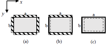
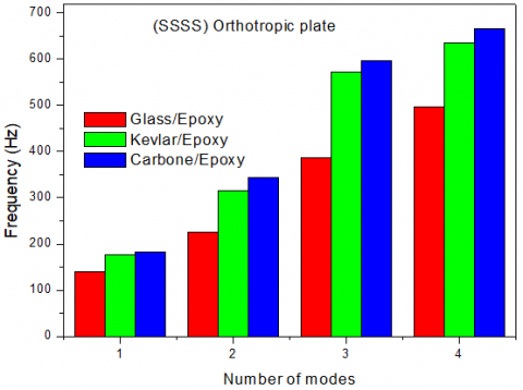
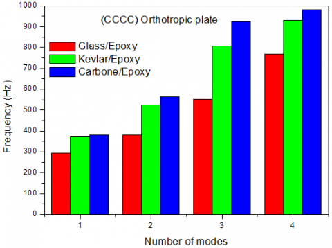
This analysis was performed for a plate with one orthotropic ply of length a=250 mm, width b=100 and thickness of 1 mm. All elastic properties listed in Table 4, were estimated after calculating the homogenized properties by using EasyPBC open-source ABAQUS CAE interface plugin [28], in case of volume fraction of fibers Vf=0.6. The effect of boundary conditions and material type are investigated. The boundary conditions are applied at all four edges of the plate, with simply support (SSSS), clamped boundary (CCCC) and simple clamped conditions (SCSC) as shown in Figure 2. The angular and natural frequencies of the plates have been obtained using Eq. (17) and Eq. (19). The fundamental natural frequency can be obtained by letting m=1 and n=1, (m and n are mode numbers). Using MATLAB, for the first four vibration modes, angular and natural frequencies are computed for all used materials and for applied boundary conditions and listed in Table 5, Table 6 and Table 7. It can be seen in Figure 3, Figure 4 and Figure 5 that the frequency values increase as number of modes increases and that whatever the material, the CCCC plate has the level of highest frequency and the SSSS plate the lowest frequency level, the SCSC plate fall between these two configurations. Also, we can see that the Carbone plate presents the highest level of frequency followed by the Kevlar then glass plate. This can be explained by the high stiffness of the Carbone plate.
Figure 2. Schematic of the considered boundary conditions: (a) clamped (CCCC), (b) simply supported / clamped (SCSC), (c) simply-supported (SSSS)
Table 4. Mechanical properties of the materials used in this Paper
|
|
Glass(E) Epoxy |
Carbone (HM) Epoxy |
Kevlar (49) Epoxy |
|
$\rho c$ (Kg/m3) |
2040 |
1650 |
1370 |
|
E1 (MPa) |
45,178.86 |
139,369.49 |
73,385.35 |
|
E2 (MPa) |
13,852.18 |
16,139.80 |
15,003.60 |
|
E3 (MPa) |
13,854.28 |
16,143.57 |
15,006.51 |
|
v12 |
0.2656 |
0.3346 |
0.3691 |
|
v13 |
0.2656 |
0.3346 |
0.3691 |
|
v23 |
0.2209 |
0.2068 |
0.2227 |
|
G12 (MPa) |
4,803.66 |
5,388.84 |
5,068.88 |
|
G13 (MPa) |
4,804.05 |
5,389.39 |
5,069.34 |
|
G23 (MPa) |
3,435.43 |
3,645.06 |
3,536.83 |
Figure 3. Natural frequencies of the simply supported orthotropic plate (SSSS)
Figure 4. Natural frequencies of the simply supported orthotropic plate (SCSC)
Figure 5. Natural frequencies of clamped orthotropic plate (CCCC)
Table 5. Angular and natural frequencies of the simply supported rectangular orthotropic plates obtained by using the Rayleigh-Ritz approach
|
|
Glass/Epoxy |
Kevlar/Epoxy |
Carbone/Epoxy |
||||
|
N° |
(m, n) |
Frequency fmn (Hz) |
Pulsation ωmn (rad/s) |
Frequency fmn (Hz) |
Pulsation ωmn (rad/s) |
Frequency fmn (Hz) |
Pulsation ωmn (rad/s) |
|
1 |
(1,1) |
140.6246 |
883.5444 |
177.0921 |
1,112.7025 |
183.4897 |
1,152.9003 |
|
2 |
(2,1) |
224.9032 |
1,413.1088 |
316.2096 |
1,986.8036 |
344.0492 |
2,161.7249 |
|
3 |
(3,1) |
386.7651 |
2,430.1171 |
571.4343 |
3,590.4280 |
597.0400 |
3,751.3134 |
|
4 |
(1,2) |
496.7636 |
3,121.2578 |
635.5573 |
3,993.3246 |
666.0067 |
4,184.6435 |
Table 6. Angular and natural frequencies of the simply supported /clamped rectangular orthotropic plates obtained by using the Rayleigh-Ritz approach
|
|
Glass/Epoxy |
Kevlar/Epoxy |
Carbone/Epoxy |
||||
|
N° |
(m, n) |
Frequency fmn (Hz) |
Pulsation ωmn (rad/s) |
Frequency fmn(Hz) |
Pulsation ωmn (rad/s) |
Frequency fmn(Hz) |
Pulsation ωmn (rad/s) |
|
1 |
(1,1) |
160.5210 |
1,008.5836 |
218.0474 |
1,370.0328 |
227.1559 |
1,427.2627 |
|
2 |
(2,1) |
284. 4284 |
1,787.1166 |
414.5913 |
2,604.9541 |
475.9437 |
2,990.4428 |
|
3 |
(3,1) |
479.7494 |
3,054.1796 |
617.6424 |
3,880.7621 |
650.7129 |
4,088.5502 |
|
4 |
(1,2) |
505.9171 |
3,178.7713 |
731.1742 |
4,594.1030 |
789.1380 |
4,958.3006 |
Table 7. Angular and natural frequencies of the clamped rectangular orthotropic plates obtained by using the Rayleigh-Ritz approach
|
|
Glass/Epoxy |
Kevlar/Epoxy |
Carbone/Epoxy |
||||
|
N° |
(m, n) |
Frequency fmn (Hz) |
Pulsation ωmn (rad/s) |
Frequency fmn (Hz) |
Pulsation ωmn (rad/s) |
Frequency fmn(Hz) |
Pulsation ωmn (rad/s) |
|
1 |
(1,1) |
293.5264 |
1,844.2267 |
371.3777 |
2,333.4355 |
381.7633 |
2,398.6899 |
|
2 |
(2,1) |
380.6673 |
2,391.8034 |
525.8076 |
3,303.7469 |
564.1705 |
3,544.7879 |
|
3 |
(3,1) |
553.1581 |
3,475.5949 |
805.7628 |
5,062.7574 |
925.6048 |
5,815.7467 |
|
4 |
(1,2) |
767.2128 |
4,820.5402 |
931.0525 |
5,849.9758 |
981.7702 |
6,168.6442 |
Nowadays, numerical simulation has become the most efficient and the most widely used calculation tool for predicting the mechanical behavior of structures during commissioning and improving the operation of industrial systems and processes. The Finite element method (FEM) is a powerful computational technique widely used for numerical simulation and optimization of structural geometry [29], based on the concept that one can replace any continuum by an assemblage of simply shaped elements with well-defined force displacement and material relationships. In this paper, geometric and FE model for the same orthotropic plates is carried out using the ABAQUS software which is one of the popular FEM software and which has been used for wide range of study. Extracting accurate results in ABAQUS depend on defining the boundary conditions, steps of the solution, type, and size of meshes carefully. In this this numerical study, the plate geometry and the boundary conditions used are shown in Figure 6.
Figure 6. Boundary conditions considered in the study: (a) clamped (CCCC), (b) simply supported / clamped (SCSC), (c) simply-supported (SSSS)
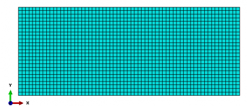
The plate is discretized into a finite number of rectangular elements. The S4R element, defined by four nodes was employed as shown in Figure 7. However, it is always good practice to perform a mesh convergence study. To perform this study, we chose a mesh of approximate global size respectively: AGS=20,10,5,4 and 3. Obtained results for the fundamental mode (m=1 and n=1), in case of simply supported plate (SSSS) made of glass, are presented in Table 8. We can notice that the nearest result into the analytical approach reference result (f11=140.6246) is when global approximate size is equal to 4.
Figure 7. Finite element model of the orthotropic rectangular plate
Table 8. Approximate global size used to achieve optimal mesh for rectangular plate
|
AGS |
Number of mesh |
f11 (Hz) |
|
20 |
65 |
146.06 |
|
10 |
250 |
141.87 |
|
5 |
1000 |
140.83 |
|
4 |
1575 |
140.70 |
|
3 |
2937 |
140.58 |
Using results extracted from ABAQUS, the first four vibration modes, for the three used materials and for applied boundary conditions are presented in Table 9, Table 10 and Table 11. Obtained results are compared with analytical natural and angular frequencies obtained by using the Rayleigh-Ritz approach. The relative error in theses Tables is estimated according to the Eq. (20).
$e \%=\frac{|F E M-A n a l y t i c a l|}{\mid \text {Analytical} \mid} \times 100$ (20)
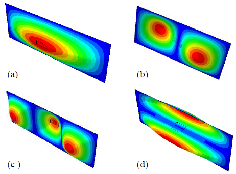
It can be seen from Table 9, Table 10, and Table 11 the agreement between results obtained with Rayleigh-Ritz approach and finite element method, with a maximum error of 1.3987%. We can notice that it is clear with increasing mode number; natural frequencies and pulsations are increased. The first four vibration modes of the plate are shown in Figure 8, in case of (SSSS) glass/epoxy plate.
Figure 8. Mode Shapes of the orthotropic rectangular plate with simply-supported boundary condition:(a): (m,n) =(1,1), (b): (m,n) =(2,1), (c): (m,n) =(3,1) and (d): (m,n) =(1,2)
Table 9. Angular and natural frequencies of the simply supported rectangular orthotropic plates obtained by using FEM approach
|
|
Glass/Epoxy |
Kevlar/Epoxy |
Carbone/Epoxy |
|||||||
|
N° |
(m, n) |
Frequency fmn (Hz) |
Pulsation ωmn (rad/s) |
% Error |
Frequency fmn (Hz) |
Pulsation ωmn (rad/s) |
% Error |
Frequency fmn (Hz) |
Pulsation ωmn (rad/s) |
% Error |
|
1 |
(1.1) |
140.70 |
884.0181 |
0.0536 |
177.15 |
1,113.0334 |
0.0326 |
183.57 |
1,153.3703 |
0.0437 |
|
2 |
(2.1) |
224.78 |
1,412.2924 |
0.0547 |
316.04 |
1,985.6793 |
0.0536 |
343.81 |
2,160.1582 |
0.0695 |
|
3 |
(3.1) |
386.83 |
2,430.4528 |
0.0167 |
571.51 |
3,590.7973 |
0.0132 |
600.63 |
3,773.7582 |
0.6012 |
|
4 |
(1.2) |
499.87 |
3,140.6832 |
0.6253 |
639.43 |
4,017.5386 |
0.6093 |
665.78 |
4,183.0957 |
0.0340 |
Table 10. Angular and natural frequencies of the simply supported /clamped rectangular orthotropic plates obtained by using FEM approach
|
|
Glass/Epoxy |
Kevlar/Epoxy |
Carbone/Epoxy |
|||||||
|
N° |
(m, n) |
Frequency fmn (Hz) |
Pulsation ωmn (rad/s) |
% Error |
Frequency fmn (Hz) |
Pulsation ωmn (rad/s) |
% Error |
Frequency fmn (Hz) |
Pulsation ωmn (rad/s) |
% Error |
|
1 |
(1,1) |
160.27 |
1006.9764 |
0.1563 |
217.78 |
1,368.3117 |
0.1226 |
226.95 |
1,425.9268 |
0.0906 |
|
2 |
(2,1) |
284. 17 |
1,785.4401 |
0.0908 |
414.23 |
2,602.6070 |
0.0871 |
475.29 |
2,986.2470 |
0.1373 |
|
3 |
(3,1) |
486.46 |
3,056.4281 |
1.3987 |
653.22 |
4,104.1812 |
0.3852 |
620.28 |
3,897.2192 |
0.4270 |
|
4 |
(1,2) |
507.85 |
3,190.8215 |
0.3820 |
731.41 |
4,595.4490 |
0.0322 |
789.90 |
4,962.9417 |
0.0965 |
Table 11. Angular and natural frequencies of the clamped rectangular orthotropic plates obtained by using FEM approach
|
|
Glass/Epoxy |
Carbone/Epoxy |
Kevlar/Epoxy |
|||||||
|
N° |
(m, n) |
Frequency fmn (Hz) |
Pulsation ωmn (rad/s) |
% Error |
Frequency fmn (Hz) |
Pulsation ωmn (rad/s) |
% Error |
Frequency fmn (Hz) |
Pulsation ωmn (rad/s) |
% Error |
|
1 |
(1,1) |
294.13 |
1,848.0187 |
0.2056 |
372.09 |
2,337.8414 |
0.1917 |
382.51 |
2,403.3103 |
0.1955 |
|
2 |
(2,1) |
380.71 |
2,392.0009 |
0.0112 |
525.69 |
3,302.9102 |
0.0223 |
563.78 |
3,542.2297 |
0.0692 |
|
3 |
(3,1) |
552.97 |
3,474.3105 |
0.0340 |
805.17 |
5,058.8831 |
0.0735 |
926.77 |
5,822.8959 |
0.1258 |
|
4 |
(1,2) |
774.09 |
4,863.6074 |
0.8963 |
933.87 |
5,867.5052 |
0.3026 |
990.39 |
6,222.6203 |
0.8779 |
3.1 Effect of geometrical parameters
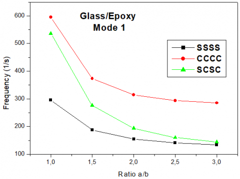
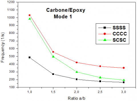
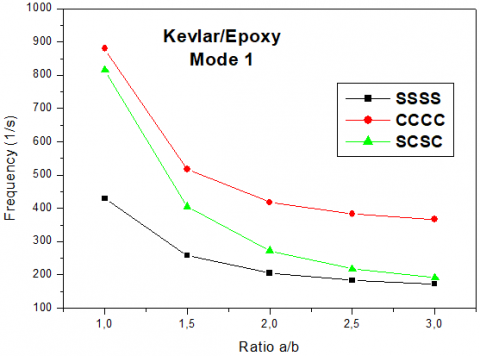
To confirm the reliability and the accuracy of the analytical and finite element approaches, a parametric study is conducted in order to examine the effect of geometrical parameters on natural vibrations of the rectangular plate. The values of frequency parameter of the plates having different (length/width) ratios in case of (a/b≥1) and for different boundary conditions used in this work, corresponding to the first natural mode (1,1), are respectively listed in Table 12, Table 13 and Table 14. As shown in Figure 9, Figure 10 and Figure 11, we can see a rapidly increasing parabolic rate for the interval a/b=1 to a/b=2. In case of (length/width) ratios a/b>2 an asymptotic attenuation is imposed. This can be explained by a transfer of rigidity going from the case finite plate into the case of infinite plate。
Figure 9. Variation of frequencies with respect to ratio a/b case of glass/epoxy plate
Figure 10. Variation of frequencies with respect to ratio a/b case of Carbone/epoxy plate
Figure 11. Variation of frequencies with respect to ratio a/b case of Kevlar/epoxy plate
Table 12. Frequencies with respect to ratio a/b case of Carbone/epoxy plate
|
a/b |
f11(Hz) (SSSS) |
f11(Hz) (CCCC) |
f11(Hz) (SCSC) |
|
1 |
486.25 |
1032.4 |
984.84 |
|
1.5 |
270.23 |
557.51 |
496.73 |
|
2 |
203.68 |
421.03 |
298.81 |
|
2.5 |
177.15 |
372.09 |
226.95 |
|
3 |
164.59 |
351.38 |
192.62 |
Table 13. Frequencies with respect to ratio a/b case of glass/epoxy plate
|
a/b |
f11(Hz) (SSSS) |
f11(Hz) (CCCC) |
f11(Hz) (SCSC) |
|
1 |
296 |
595.36 |
536.15 |
|
1.5 |
188.13 |
373.24 |
276.24 |
|
2 |
154.65 |
314.7 |
193.67 |
|
2.5 |
140.7 |
294.13 |
160.27 |
|
3 |
133.68 |
285.2 |
144.54 |
Table 14. Frequencies with respect to ratio a/b case of Kevlar/epoxy plate
|
a/b |
f11(Hz) (SSSS) |
f11(Hz) (CCCC) |
f11(Hz) (SCSC) |
|
1 |
428.65 |
879.74 |
815.06 |
|
1.5 |
258.03 |
516.59 |
405.17 |
|
2 |
205.24 |
417.48 |
272.36 |
|
2.5 |
183.57 |
382.51 |
217.78 |
|
3 |
172.89 |
367.50 |
191.95 |
3.2 Passive vibration control using patches
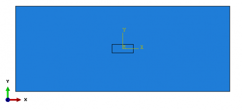
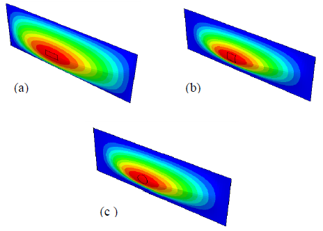
This section presents simulations and research results of testing the passive vibration control with damping patches bonded to the top surface of the Carbone/epoxy plate used and analyzed previously in this study as is depicted in Figure 12. For various boundary conditions: simply supported (SSSS), clamped (CCCC) and simply supported/clamped (SCSC), a Carbone/epoxy test plate of dimensions 250x100x1 mm3 is modeled in ABAQUS and meshed with S4R elements. Three rectangular patches denoted P1, P2 and P3, made of one layer of orthotropic glass/epoxy and of sections representing respectively 1, 2 and 3% of the plate section, are glued to the center of the plate as shown in the Figure 12. The glass/epoxy was considered because this material has the lowest frequency level. Also, the patch was modeled with S4R elements as shown in Figure 13. Note that the material properties of both plate and patch are listed in Table 4. The mode shapes of the plate with patch corresponding to the four first modes are presented in Figure 14. Using data extracted from ABAQUS, the natural frequencies of vibration corresponding to the first four modes are obtained with and without damping patches and listed in Tables 15, 16 and 17. The relative error between plate’s frequencies with and without dumping patches is computed and presented in the same Table. It is observed that for the three configurations of considered boundary conditions, the patch P3 which covers 3% of the surface area of the plate offers the minimized vibration level with a reduction in frequency which retches 13.4026%, in case of clamped plate. It is clear that with increasing the surface area of the patch we can control better the plate frequency level. In this investigation we also examined the influence of the patch geometry on the passive control of plate vibration. We consider three fully clamped plates with rectangular, square and circular patches attached to the center as shown in Figure 15 witch cover 1% of the global surface area. It can be seen from the results presented in Table 18 that the rectangular patch gives the maximum reduction level in frequency.
Figure 12. Considered plate with attached damping patch
Figure 13. Meshing model (plate with patch) using S4R elements
Figure 14. Mode shapes of the plate with patch for the first four modes (a): (1,1), (b):(2,1), (c):(3,1) and (d): (1,2)
Table 15. Natural frequencies of vibration corresponding to the first four modes obtained with and without damping patches case of clamped plate
|
Mode
|
Frequency Plate only |
Frequency (Hz) with patch (P1) |
Diff % |
Frequency (Hz) with patch (P2) |
Diff % |
Frequency (Hz) with patch (P3) |
Diff % |
|
1 |
372.09 |
363.18 |
2.3946 |
341.84 |
8.1297 |
322.22 |
13.4026 |
|
2 |
563.78 |
559.42 |
0.7733 |
555.03 |
1.5520 |
531.38 |
5.7469 |
|
3 |
926.77 |
911.41 |
1.6573 |
891.62 |
3.7927 |
884.61 |
4.5491 |
|
4 |
933.87 |
926.05 |
0.8373 |
922.17 |
1.2528 |
895.55 |
4.1033 |
Table 16. Natural frequencies of vibration corresponding to the first four modes obtained with and without damping patches case of simply supported plate
|
Mode
|
Frequency Plate only |
Frequency (Hz) with patch (P1) |
Diff % |
Frequency (Hz) with patch (P2) |
Diff % |
Frequency (Hz) with patch (P3) |
Diff % |
|
1 |
177.15 |
174.93 |
1.2531 |
168.79 |
4.7191 |
162.99 |
7.9932 |
|
2 |
343.81 |
342.63 |
0.3432 |
341.05 |
0.8027 |
332.62 |
3.2547 |
|
3 |
600.63 |
598.38 |
0.3746 |
596.72 |
0.6509 |
586.76 |
2.3092 |
|
4 |
665.78 |
656 |
1.4689 |
639.67 |
3.9217 |
632.5 |
4.9986 |
Table 17. Natural frequencies of vibration corresponding to the first four modes obtained with and without damping patches case of simply supported/clamped plate
|
Mode
|
Frequency Plate only |
Frequency (Hz) with patch (P1) |
Diff % |
Frequency (Hz) with patch (P2) |
Diff % |
Frequency (Hz) with patch (P3) |
Diff % |
|
1 |
226.95 |
222.66 |
1.8902 |
211.94 |
6.6137 |
201.6 |
11.1698 |
|
2 |
475.29 |
474.87 |
0.0883 |
469.01 |
1.3212 |
451.23 |
5.0621 |
|
3 |
620.28 |
619.95 |
0.0532 |
615.45 |
0.7786 |
603.56 |
2.6955 |
|
4 |
789.9 |
786.98 |
0.3696 |
784.47 |
0.6874 |
781.08 |
1.1165 |
Table 18. Natural frequencies corresponding to the first four modes obtained with and without: rectangular, square and circular patches case of clamped plate
|
Mode
|
Frequency Plate only |
Frequency plate with rectangular patch |
Diff % |
Frequency plate with square patch |
Diff % |
Frequency plate with circular patch) |
Diff % |
|
1 |
372.09 |
363.18 |
2.3945 |
366.39 |
1.5318 |
367.6 |
1.2066 |
|
2 |
563.78 |
559.42 |
0.7733 |
560.23 |
0.6296 |
563.66 |
0.0212 |
|
3 |
926.77 |
911.41 |
1.6573 |
912.99 |
1.4868 |
913.68 |
1.4124 |
|
4 |
933.87 |
926.05 |
0.8373 |
933.29 |
0.0621 |
933.83 |
0.0042 |
Figure 15. Different patches shapes attached to the plate:(a): rectangular, (b): square and (c): circular
The present study provides a modal analysis of orthotropic thin rectangular plate to determine its natural frequencies and mode shapes by using analytical method based on Rayleigh-Ritz energy approach. The obtained results were compared with those computed with ABAQUS software. The second part of this work covered the study of the effects of geometrical parameters and boundary conditions on vibratory behaviour of the plate. Also, the paper presents simulations results of testing of the plate with passive vibration control. From the analytical and numerical results, the following conclusions can be stated:
In case of rectangular structures, rectangular patch gives the maximum reduction level in frequency compared with square and circular patches.
The authors like to thank the Algerian general direction of research (DGRSDT) for their support.
[1] Deghboudj, S., Boukhedena, W., Satha, H. (2016). Analyse numérique de la concentration de contraintes dans une plaque composite sollicitée en tractioncomportant deux trous. Revue des Composites et des Matériaux Avancés, 26(2): 147-163. http://doi.org/10.3166/RCMA.26.147-163
[2] Warburton, G.B. (1954). The vibration of rectangular plates. Proceeding of the Institute of Mechanical Engineers, 168(1): 371-384. https://doi.org/10.1243%2FPIME_PROC_1954_168_040_02
[3] Leissa, A.W. (1969). Vibration of Plates. NASA SP-160, Washington DC.
[4] Hearmon, R.F.S. (1959). The frequency of flexural vibration of rectangular plates with clamped or simply supported edges. Journal of Applied Mechanics, 26: 537-540.
[5] O’Boy, D.J., Krylov, V.V. (2016). Vibration of a rectangular plate with a central power-law profiled groove by the Rayleigh-Ritz method Applied Acoustics. Applied Acoustics, 104: 24-32. https://doi.org/10.1016/j.apacoust.2015.10.018
[6] Hosseini-Hashemi, S., Fadaee, M., Taher, H.R.D. (2011). Exact solutions for free flexural vibration of Lévy-type rectangular thick plates via third-order shear deformation plate theory. Applied Mathematical Modelling, 35(2): 708-727. http://doi.org/10.1016/j.apm.2010.07.028
[7] Ramu, I., Mohanty, S.C. (2012). Study on free vibration analysis of rectangular plate structures using finite element method. Procedia Engineering, 38: 2758-2766. http://doi.org/10.1016/j.proeng.2012.06.323
[8] Werfalli, N.M., Karoud, A.A. (2016). Free vibration analysis of rectangular plates using Galerkin-based finite element method. International Journal of Mechanical Engineering, 2(2): 2277-7059.
[9] Mama, B.O., Onah, H.N., Ike, C.C., Osadebe, N.N.N. (2017). Solution of free harmonic equation of simply supported Kirchhoff plates using Galerkin-Valsov method. Nigerian Journal of Technology, 36(2): 361-365. http://dx.doi.org/10.4314/njt.v36i2.6
[10] Haţiegan, C., Gillich, E.V., Vasile, O., Nedeloni, M., Pădureanu, L. (2015). Finite element analysis of thin plates clamped on the rim of different geometric forms, Part I: Simulating the Vibration Mode Shapes and Natural Frequencies. Romanian Journal of Acoustics & Vibration, 12(1): 69-74.
[11] Pouladkhan, A.R., Emadi, J., Safamehr, M., Habibolahiyan, H. (2011). The vibration of thin plates by using modal analysis. World Academy of Science, Engineering and Technology, 59: 2880-2885.
[12] Rock, T., Hinton, E. (1974). Free vibration and transient response of thick and thin plates using the finite element method. Earthquake Engineering & Structural Dynamics, 3(1): 51-63. http://doi.org/10.1002/eqe.4290030105
[13] Liu, G.R., Chen, X.L. (2001). A mesh-free method for static and free vibration analyses of thin plates of complicated shape. Journal of Sound and Vibration, 241(5): 839-855. http://doi.org/10.1006/jsvi.2000.3330
[14] Zhou, Z.H., Wong, K.W., Xu, X.S., Leung, A.Y.T. (2011). Natural vibration of circular and annular thin plates by Hamiltonian approach. Journal of Sound and Vibration, 330(5): 1005-1017. http://doi.org/10.1016/j.jsv.2010.09.015
[15] Benamar, R., Bennouna, M.M.K., White, R.G. (1993). The effects of large vibration amplitudes on the mode shapes and natural frequencies of thin isotropic plates. Journal of Sound and Vibration, 164(2): 295-316. http://doi.org/10.1066/jsvi.1993.1215
[16] Alfano, M., Pagnotta, L. (2006). Determining the elastic constants of isotropic materials by modal vibration testing of rectangular thin plates. Journal of Sound and Vibration, 293(1-2): 426-439. http://doi.org/10.1016/j.jsv.2005.10.021
[17] Hanna, N.F., Leissa, A.W. (1994). A higher order shear deformation theory for the vibration of thick plates. Journal of Sound and Vibration, 170(4): 545-555. http://doi.org/10.1006/jsvi.1994.1083
[18] Dozio, L. (2011). On the use of the Trigonometric Ritz method for general vibration analysis of rectangular Kirchhoff plates. Thin-Walled Structures, 49(1): 129-144. http:// doi.org/10.1016/j.tws.2010.08.014
[19] Vescovini, R., Dozio, L., D'Ottavio, M., Polit, O. (2018). On the application of the Ritz method to free vibration and buckling analysis of highly anisotropic plates. Composite Structures, 192: 460-474. https://doi.org/10.1016/j.compstruct.2018.03.017
[20] Ahmadian, M., Jeric, K.M. (2001). On the application of shunted piezoceramics for increasing acoustic transmission loss in structures. Journal of Sound and Vibration, 243(2): 347-359. http://doi.org/10.1006/jsvi.2000.3417
[21] Branski, A., Szela, S. (2007). On the quasi optimal distribution of PZTs in active reduction of the triangular plate Vibration. Archives of Control Sciences, 17(4): 427-437.
[22] Wang, B.T., Fuller, C.R., Dimitriadis, E.K. (1991). Active control of noise transmission through rectangular plates using multiple piezoelectric or point force actuators. The Journal of the Acoustical Society of America, 90(5): 2820. https://doi.org/10.1121/1.401879
[23] Timoshenko, S.P., Woinowsky-Krieger, S. (1959). Theory of Plates and Shells. McGraw- Hill Book Company, New York.
[24] Mindlin, R.D. (1951). Influence of rotatory inertia and shear on flexural motions of Isotropic elastic plates. Journal of Applied Mechanics, 18: 31-38.
[25] Reddy, J.N. (1984). A simple higher-order theory for laminated composite plates. Journal of Applied Mechanics, 51(4): 745-752. https://doi.org/10.1115/1.3167719
[26] Ciarlet, P.G. (1988). Mathematical Elasticity: Volume I: Three-Dimensional Elasticity. Studies in Mathematics and Its Applications. North Holland Amsterdam, 190-195.
[27] Berthelot, J.M. (1999). Mechanics of Composite Materials and Structures, Springer, New York.
[28] Omairey, S.L., Dunning, P.D., Sriramula, S. (2019). Development of an ABAQUS plugin tool for periodic RVE homogenisation. Engineering with Computers, 35: 567-577. https://doi.org/10.1007/s00366-018-0616-4
[29] Deghboudj, S., Boukhedena, W., Satha, H. (2018). Experimental and finite element analysis of in-plane shear properties of a carbon non-crimp fabric at macroscopic scale. Journal of Composite Materials, 52(2): 235-244. http://doi.org/10.1016/S0022-460X(73)80371-2