Yagebai Zhao* | Puzheng Ding | Ying Zhao | Xuwen Yan
OPEN ACCESS
This paper mainly carries out the preliminary work for the design of an innovative three-way seismic isolator based on the metallic pseudo rubber-silicon rubber (MPR-SR) composite. First, the MPR-SR composite was prepared by adding the SR, a high-molecular polymer, to the MPR, and several MPR-SR specimens of different molding densities were prepared. Next, the specimens were subjected to compression and shear tests under quasi-static and dynamic loads, respectively. Several tests were carried out to reflect how these behaviors are affected by load amplitude, cycle count, loading frequency and molding density. The mechanical properties and damping features between the specimens were compared and analyzed in details. On this basis, the author examined the mechanical properties and SI mechanism of the MPR-SR composite. The results show that the MPR-SR composite has good recoverability under compressive and shear deformations: the composite can recover even if 40% of it has been deformed under compression and 80% under shear load; the hysteretic energy dissipation ability of the composite increases with the molding density; the loading frequency and cycle number have basically no impact on the compressive hysteretic behavior of the composite. To sum up, the MPR-SR enjoys good stiffness and energy dissipation ability, and serves as an excellent material for anti-corrosion, antioxidant three-way seismic isolator.
metallic pseudo rubber-silicon rubber (MPR-SR) composite, three-way seismic isolator, compression, shear, hysteretic behavior
Since the 1960s, seismic isolation (SI) has been widely studied and applied in buildings. It is generally agreed that the SI is the most mature and effective means to reduce the structural seismic damage for low-rise buildings and bridges [1-2]. The laminated rubber bearing is by far the most popular and well-developed SI devices [3-4]. Following the Great Hanshin earthquake in 1995, an obvious vertical seismic effect has been found in buildings under the action of near-field ground motions, especially in bridges and other large-span structures [5-9]. However, most of the available seismic isolators only dampen the horizontal seismic response of structures. As a result, it is highly necessary to develop a simple SI device that isolates seismic motions in both horizontal and vertical directions. Against this backdrop, this paper proposes to design a novel three-way SI device using metallic pseudo rubber-silicon rubber (MPR-SR) composite, and explores the mechanical properties of the MPR-SR composite in all three directions.
The metallic pseudo rubber (MPR) is an elastic porous material. It is usually prepared in three steps: winding thin metal wires into spring coils, weaving the spring coils into a mesh, and pressing the mesh into the MPR. In the MPR, the metal wires interlaced with each other, forming a network structure like the macromolecular structure of rubber. As its name suggests, the MPR enjoys a rubber-like elasticity [10-12]. Under external load, friction, slippage, compression and deformation will occur between steel wire spring coils. A large amount of energy is thus dissipated, exerting a damping effect. According to the experimental data in previous literature, the MPR-SR composite element based on Cr18Ni9Ti austenitic stainless-steel wires has low tensile strength and shear stiffness, and cannot fully dissipate the vibration energy of a structure under a heavy load [13-18]. The silicon rubber (SR) is a linear high-molecular weight polyorganosiloxane, featuring good high-temperature resistance and excellent damping performance. The mechanical properties of the SR are stable in a wide range of temperatures (-50~200℃) [19-20].
This paper mainly carries out the preliminary work for the design of a three-way seismic isolator based on the MPR-SR composite. Specifically, MPR-SR specimens of different molding densities were prepared by adding the SR, a high-molecular polymer, and the curing agent into the MPRs, which differ in molding density, at a fixed mix ratio. The prepared MPR-SR specimens were subjected to a compressive test and a two-way shear test under quasi-static and dynamic loads, respectively. Based on the test results, the author analyzed the influence laws of factors like loading amplitude, number of load cycles, and loading frequency on the compressive and shear hysteretic behaviors of the MPR-SR composite, and examined the hysteretic energy dissipation and deformation recovery of the material. The research results lay a solid basis for setting up the constitutive model of the composite material and developing a novel three-way seismic isolator based on the composite.
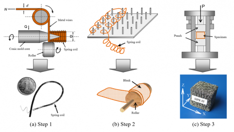
As shown in Figure 1, the MPR specimens were prepared in three steps: (1) Draw the fine metal wires and wind them into spring coils; (2) Weave the spring coils into a mesh, and fold the mesh into multiple layers, forming a blank; (3) Place the blank into a mold and punch it into the desired shape. The details on the processing techniques of the MPR are available in relevant literature [21-22]. Our MPR specimens were made of 0Cr18Ni9Ti austenitic stainless-steel wires, with the diameter of 0.2mm. The outer diameter of spring coil was set to 1.7mm. The blank was molded under the pressure of 5t/cm2, and tempered at 400℃ [23-27]. The serial numbers and geometric dimensions of the specimens are listed in Table 1. The molding density is an important parameter of each MPR specimen. It refers to the ratio of the specimen density to the density of the raw material.
Figure 1. Preparation of the MPR composite
Table 1. Parameters of the MPR specimens
|
Parameters Specimens |
Outer diameter of stainless-steel wire mm |
Molding density |
Mass g |
Dimensions mm |
Loading pattern |
|
MPR I |
0.2 |
0.23 |
28 |
25×25×25 |
Compression and shear |
|
MPR II |
0.2 |
0.25 |
30 |
25×25×25 |
Compression and shear |
|
MPR III |
0.2 |
0.27 |
33 |
25×25×25 |
Compression and shear |
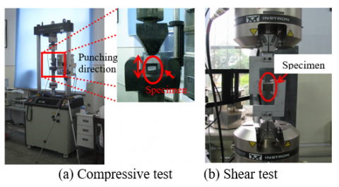
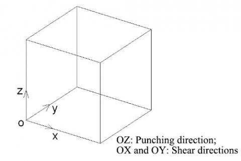
The mechanical properties of the MPR-SR composite were tested on an Instron FastTrack 8801 servo-hydraulic fatigue testing system in a mechanics lab of Harbin Institute of Technology. The testing system can apply a cyclic load (≤100kN) at the maximum frequency of 50Hz. During the tests, the load was applied by controlling the specimen deformation. The forces and deformation of the specimen were collected by the force sensor and displacement sensor on the testing system, and converted into stress and strain according to the dimensions of the specimen. Each specimen was subjected to a cyclic compressive load in the punching direction (OZ in Figure 1(c)), and then cyclic shear loads in the two directions perpendicular to the punching direction (OX and OY in Figure 1(c)). The measured data were analyzed to evaluate the compressive and shear strengths of the specimen in the three directions. The photos of the specimen and testing system in the tests are displayed in Figures 2(a) and 2(b), respectively.
Figure 2. Specimen and testing system of MPR-SR compression and shear tests
Firstly, quasi-static compressive loads were applied cyclically to MPR-SRs I, II and III, which differ in molding density. The loads were applied in the punching direction of the MPR. The deformation was controlled within 6mm (24%), allowing the specimen to recover. During the test, each specimen was compressed unidirectionally at a constant speed (5mm/min), with a strain amplitude of 2%, 5%, 10%, 15%, and 20%, respectively. The cyclic loading was repeated five times for each strain amplitude, and the specimen under one cyclic loading was selected for quasi-static failure test. The recoverability of the specimen was tested under two strain amplitudes, namely, 30% and 40%.
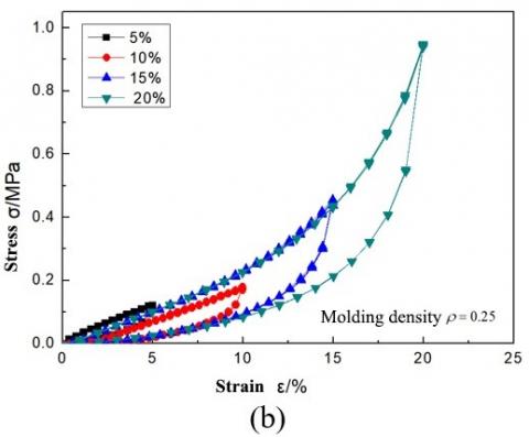
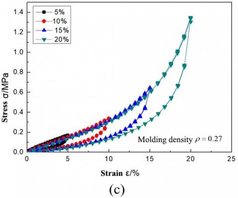
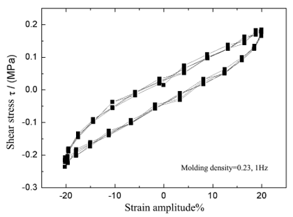
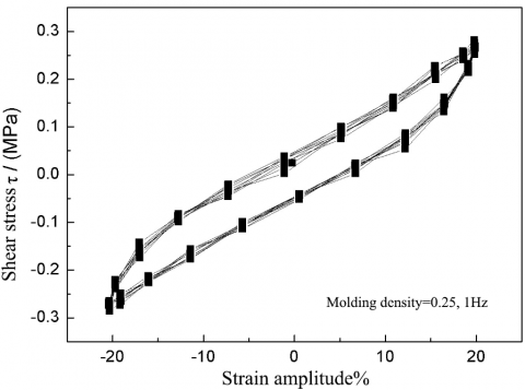
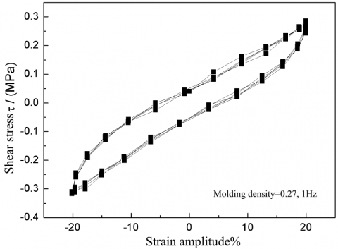
Figures 3(a), (b) and (c) are the stress-strain hysteresis curves of MPR-SRs I, II and III under different strain amplitudes, respectively. It can be seen that, with the growing strain amplitude, the elastic modulus of the composite increased, and the loading segment of each curve exhibited an obvious feature of strain hardening. This feature is very useful to develop a seismic isolator based on the MPR-SR. The recoverability of such an isolator increases with the deformation, which is conducive to dissipating the energy of civil structures.
Moreover, the greater the deformation amplitude, the plumper the hysteresis curve of each MPR-SR specimen, indicating a good ability of hysteretic energy dissipation. The main reason lies in that: when the deformation is small, the metal wires have not overcome the friction between them, slowing an unobvious slip; as the deformation amplitude grows, the slip between the metal wires become obvious, dissipating more energy.
Figure 3. Stress-strain hysteresis curves of the three specimens under quasi-static compression
It can also be seen that the cycle number has little impact on the stress-strain hysteresis features of each MPR-SR specimen. Under each working condition, the stress-strain curves of almost all cycles were highly repeatable. The only exception is the stress-strain curve of the second cycle, which shows a slight stress degradation compared to that of the first cycle. This means the MPR-SR has stable stress-strain features under compression, despite the growing number of loading cycles.
According to the test results, no specimen suffered from residual deformation, even if the strain amplitude reached 20%. Thus, the MPR-SR composite boasts excellent elasticity and can recover from large deformation. These properties make the composite a desirable material for SI devices.
The equivalent damping ratio was introduced to compare the damping performance between specimens with different molding densities [28]:
$\zeta=\frac{W_{D}\left(a_{0}\right)}{4 \pi W_{S}}$ (1)
where, a0 is the deformation amplitude; WD(a0) is the mean area under the hysteresis curve (AUHC) at a0; $W_{S}=\frac{1}{2} K a_{0}^{2}$ is the maximum elastic potential energy of the structure; K is the equivalent stiffness, which is approximated by the slope of the straight line connecting the start and end points of the force-displacement curve (Figure 4):
$K=\frac{F_{0}}{a_{0}}$ (2)
Figure 4. Calculation of the equivalent stiffness
The equivalent damping ratios of each of the three specimens were calculated for different strain amplitudes. The calculation results are recorded in Table 2.
Table 2. The equivalent damping ratios $\zeta$ of the MPR-SR specimens
|
Strain amplitudes |
5% |
10% |
15% |
20% |
|
|
Equivalent damping ratio $\zeta$ |
MPR-SR I (r=0.23) |
0.039 |
0.037 |
0.032 |
0.026 |
|
MPR-SR II (r=0.25) |
0.055 |
0.044 |
0.037 |
0.028 |
|
|
MPR-SR III (r=0.27) |
0.059 |
0.045 |
0.038 |
0.033 |
|
As shown in Table 2, at each strain amplitude, the equivalent damping ratio increased with the molding density of the MPR-SR specimen.
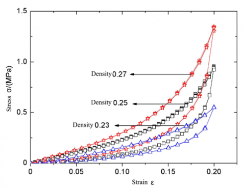
Figure 5. The stress-strain hysteresis curves of specimens with different molding densities under quasi-static compression
To disclose the influence of molding density on damping performance, the stress-strain curves of the three specimens at the strain amplitude of 20% were compared (Figure 5). It can be seen that, under the same strain amplitude, the specimen with relatively high molding density had a high compressive stress, because the elastic modulus of the MPR-SR composite is positively correlated with molding density.
Through Matlab computation, the AUHCs of MPR-SRs I, II and III were obtained as 0.271, 0.402 and 0.506, respectively, at the strain amplitude of 20%. Obviously, the AUHC expanded with the growth in molding density. This is because the specimen of a high molding density has lots of metal wires per unit volume, i.e. the friction is high between the metal wires in the specimen. During the loading/unloading process, the metal wires spend much energy to overcome the frictional damping, which promotes the damping performance of the specimen.
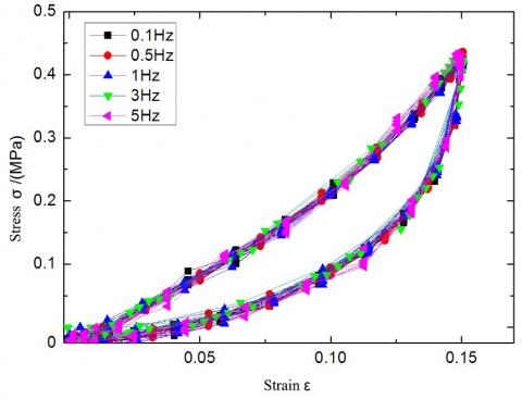
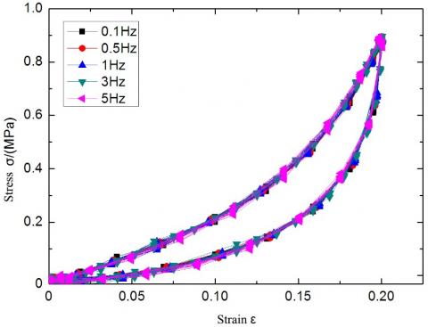
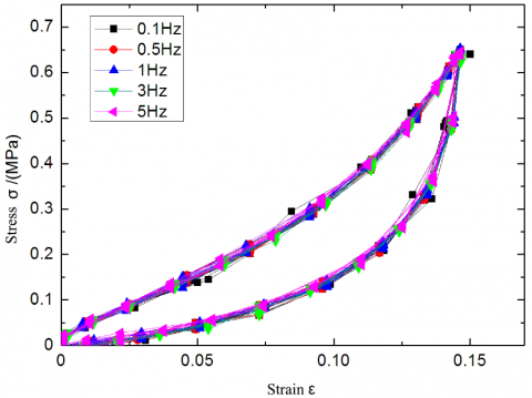
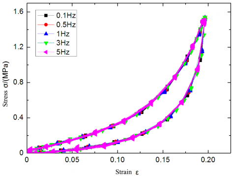
To reveal the effects of loading/unloading frequency on compressive performance, the stress-strain hysteretic behaviors of the MPR-SR composite were tested under dynamic cyclic loads of different amplitudes and frequencies. Four loading frequencies were adopted, namely, 0.1Hz, 0.5Hz, 1Hz, 3Hz and 5Hz. Under each loading frequency, four strain amplitudes were tested, including 5%, 10%, 15%, and 20%. The cyclic load was applied 20 times under each working condition.
Figures 6(a)~(d) present the stress-strain hysteresis curves of MPR-SR I and MPR-SR III under different loading frequencies and at the strain amplitudes of 15% and 20%, respectively. It can be seen that the loading frequencies exerted an insignificant impact on the stress-strain hysteretic behaviors of the MPR-SR composite. Therefore, it is concluded that the compressive energy dissipation ability of the MPR-SR composite does not change with the loading frequency.
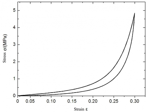
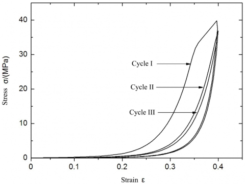
To identify the limit of irrecoverable strain of the MPR-SR composite, the MPR-SR I specimen was applied 30% and 40% compressive strains, respectively. The compressive load was loaded and unloaded five times under each strain. Figures 7 and 8 display the stress-strain curves of the specimen at the compressive strains of 30% and 40%, respectively.
(a) Stress-strain curves of the MPR-SR I at the strain amplitude of 15%
(b) Stress-strain curves of the MPR-SR I at the strain amplitude of 20%
(c) Stress-strain curves of the MPR-SR III at the strain amplitude of 15%
(d) Stress-strain curves of the MPR-SR III at the strain amplitude of 20%
Figure 6. Stress-strain hysteresis curves of the specimens under different frequencies of dynamic compressive loads
Figure 7. Stress-strain hysteresis curves of the MPR-SR I at the strain amplitude of 30%
Figure 8. Stress-strain hysteresis curves of the MPR-SR III at the strain amplitude of 40%
As shown in the two figures, no obvious residual deformation was observed on the specimen at the strain amplitude of 30%; however, residual deformation appeared on the specimen at the strain amplitude of 40%, indicating that the strain is not fully recoverable. In addition, the residual deformation increased with the applied force. In the end, the stainless-steel wires that make up the specimen were severely deformed, e.g. bulging and even breaking, and the specimen failed in the shape of a Chinese waist drum (bugled in the middle). According to our measurements, the residual strain of the specimen was about 20%.
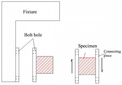
Similar to the compression test, the shear test was also performed on the Instron FastTrack 8801 servo-hydraulic fatigue testing system. Each specimen was subjected to static and dynamic cyclic loads along two directions perpendicular to the punching direction (Figure 9). Then, the shear strength, shear deformation, hysteretic behavior and shear stiffness of the MPR-SR composite were tested and computed at room temperature.
Each specimen was fixed onto the connecting piece of the shear fixture (Figure 10). Two symmetrical fixtures moved alternatively to complete the loading. To ensure that the specimen is deformed in the recoverable range, the strain amplitudes were set to 5%, 10%, 15% and 20% in turn, while the dynamic loading frequency was set to 0.1Hz, 0.5Hz, 1Hz and 3Hz, respectively. The waveform of the loading is a sine wave. Each specimen was applied 10 cycles of static load and 20 cycles of dynamic load.
Figure 9. Loading directions of the MPR-SR composite
Figure 10. The fixture of the shear test
4.1 Influence of loading frequency on hysteretic behavior
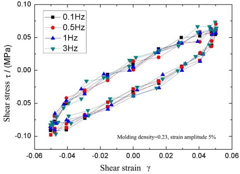
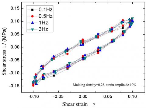
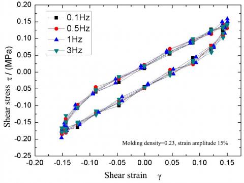
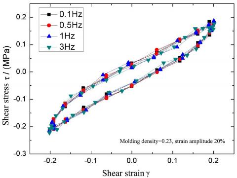
The Instron FastTrack 8801 servo-hydraulic fatigue testing system was adopted for both static and dynamic testing, because the two test methods share the same mechanical principle. The only difference between them lies in the type of sensors [36-40]. To verify whether loading frequency affects the shear performance of the MPR-SR composite, the specimen MPR-SR I was loaded at different frequencies: 0.1Hz, 0.5Hz, 1Hz and 3Hz. Figures 11 (a), (b), (c) and (d) show the shear stress-strain hysteresis curves of the specimen under strain amplitudes of 5%, 10%, 15% and 20%, respectively, at different loading frequencies.
As shown in Figure 11, the MPR-SR composite basically had identical hysteresis curves under the same strain amplitude, despite the variation in the frequency of shear load. Therefore, the loading frequency of the shear force has a negligible influence on the shear performance, that is, the shear energy dissipation ability of the MPR-SR composite does not change with the loading frequency. Therefore, the same frequency can be adopted for the dynamic shear test on MPR-SRs II and III. Due to the presence of dry friction damping, the recoverability of the MPR-SR composite might be asymmetry across the Y-axis under sine wave loading, which ultimately depends on the nature of the material.
(a) Hysteresis curves of the MPR-SR I at the strain amplitude of 5%
(b) Hysteresis curves of the MPR-SR I at the strain amplitude of 10%
(c) Hysteresis curves of the MPR-SR I at the strain amplitude of 15%
(d) Hysteresis curves of the MPR-SR I at the strain amplitude of 20%
Figure 11. Shear stress-strain curves of the MPR-SR I under different loading frequencies
4.2 Influence of loading direction and cycle number on hysteretic behavior
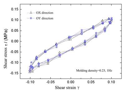
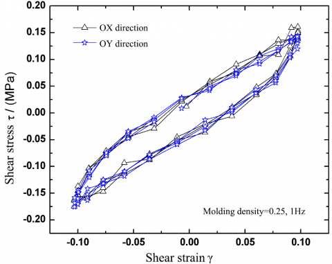
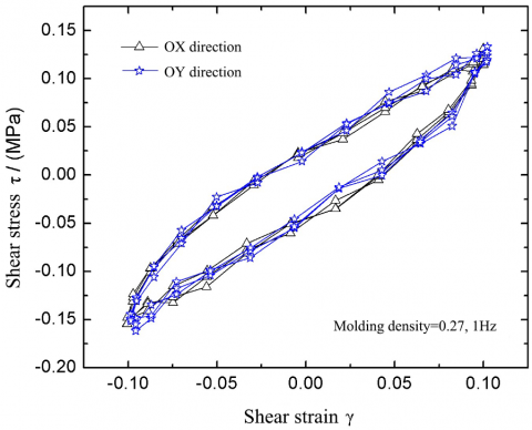
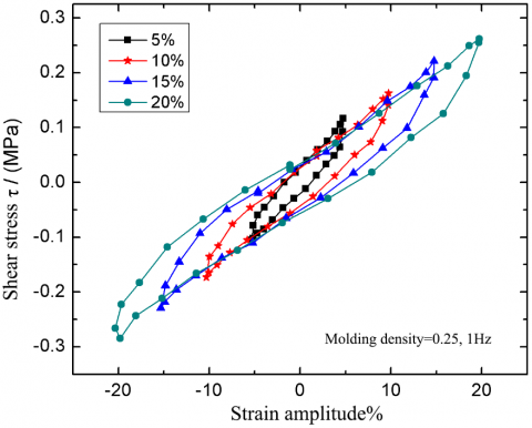
The shear loading/unloading was carried out on MPR-SRs I, II and III, respectively, in two mutually orthogonal directions (OX and OY), aiming to disclose how the specimens vary in the shear performance on the non-compressed surface. Figures 12 shows the shear stress-strain hysteresis curves of MPR-SRs I, II and III at the loading frequency of 1Hz and the strain amplitude of 10%, respectively. It is easy to observe that the hysteresis curves of each specimen in the two directions were basically coincident, when the specimens were loaded in OX and OY directions. Therefore, the two mutually perpendicular non-compressed surfaces of the MPR-SR composite have basically the same hysteretic behavior.
(a) Shear stress-strain curves of MPR-SR I
(b) Shear stress-strain curves of MPR-SR II
(c) Shear stress-strain curves of MPR-SR III
Figure 12. Shear stress-strain curves of specimens along OX and OY directions
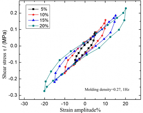
Figure 13 presents the shear hysteresis curves of MPR-SRs I, II and III at the strain amplitude of 20% and loading frequency of 1Hz, after being loaded/unloaded for 10 cycles. It can be seen that the cycle number has virtually no impact on the hysteretic behavior of the MPR-SR composite; no degradation was observed in energy dissipation ability; the stress-strain curves of all the cycles were repeatable. Hence, the MPR-SR composite boasts very stable shear energy dissipation ability.
(a) Shear stress-strain hysteresis curves of MPR-SR I
(b) Shear stress-strain hysteresis curves of MPR-SR II
(c) Shear stress-strain hysteresis curves of MPR-SR III
Figure 13. Shear stress-strain curves of specimens with different molding frequencies
The test results also show that the MPR-SR composite has good elasticity in the shear directions; no residual deformation appeared when the strain reached 20%. Similar to the results of static shear loading, the loading segment in the shear stress-strain curve of the MPR-SR composite was approximately linear, with an unobvious strain hardening effect.
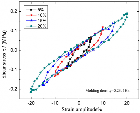
4.3 Influence of strain amplitude on hysteretic behavior
Figures 14(a), (b) and (c) are the hysteresis curves of MPR-SRs I, II and III at different strain amplitudes, when the loading frequency is 1Hz. For each specimen, the most representative curve was selected from the hysteresis curves in the ten loading/unloading cycles. It can be seen that, with the growth in strain amplitude, the AUHC of each specimen was on the rise, indicating that the composite consumed an increasingly high amount of energy. This trend can be explained as follows: when the deformation is small, the metal wires have not overcome the friction between them, slowing an unobvious slip; as the deformation amplitude grows, the slip between the metal wires become obvious, dissipating more energy.
(a) Shear stress-strain hysteresis curves of MPR-SR I
(b) Shear stress-strain hysteresis curves of MPR-SR II
(c) Shear stress-strain hysteresis curves of MPR-SR III
Figure 14. Shear stress-strain curves of the three specimens along the OX direction at different strain amplitudes and the loading frequency of 1Hz
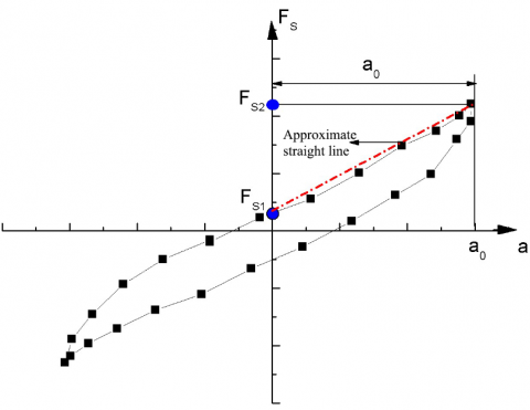
Since the loading segment of each stress-strain curve is almost linear, the equivalent shear stiffness can be approximated from the elastic hysteresis curve obtained through the test:
$K_{S}=\frac{F_{S 2}-F_{S 1}}{a_{2}-a_{1}}$ (3)
where, a1 and a2 are the maximum horizontal displacements in the negative and positive directions, respectively; FS1 and FS2 are the shear forces corresponding to a1 and a2, respectively. The calculation process of the equivalent shear stiffness is illustrated in Figure 15.
Figure 15. The equivalent shear stiffness
Then, the equivalent damping ratios of MPR-SRs I, II and III at different strain amplitudes can be computed by formula (1):
$\zeta=W_{D}\left(a_{0}\right) / 4 \pi W_{S}$ (4)
4.4 Influence of molding density on hysteretic behavior
Table 3 lists the relationship between equivalent shear stiffness, equivalent damping ratio and strain amplitude for the three specimens with different molding densities. It can be seen that the equivalent shear stiffness of each MPR-SR specimen exhibits a rising trend with the growth in the molding density. Under the same strain amplitude, the higher the molding density, the greater the equivalent shear stiffness. This is because the specimen of a high molding density has lots of metal wires per unit volume. When the deformation amplitude is the same, numerous metal wires rub against each other in such a specimen, pushing up the friction between wires and thus the shear stiffness. This means the SI effect of the MPR-SR composite along the shear directions increases with its molding density.
It can also be seen from Table 3 that, with the increase in the strain amplitude, the shear stiffness of each specimen exhibited a slightly decline, indicating that the shear strain has a limited impact on the lateral shear stiffness. Overall, the equivalent damping ratio is negatively correlated with the strain amplitude.
Table 3. The relationship between equivalent shear stiffness, equivalent damping ratio and strain amplitude for the three specimens with different molding densities
|
|
MPR-SR I (Molding density: 0.23) |
MPR-SR II (Molding density: 0.25) |
MPR-SR III (Molding density: 0.27) |
|||
|
Strain amplitude |
Equivalent stiffness (kN/mm) |
Equivalent damping ratio $\zeta$ |
Equivalent stiffness (kN/mm) |
Equivalent damping ratio $\zeta$ |
Equivalent stiffness (kN/mm) |
Equivalent damping ratio $\zeta$ |
|
5% |
0.043 |
0.142 |
0.041 |
0.145 |
0.036 |
0.147 |
|
10% |
0.039 |
0.119 |
0.035 |
0.128 |
0.032 |
0.131 |
|
15% |
0.035 |
0.108 |
0.032 |
0.112 |
0.030 |
0.119 |
|
20% |
0.028 |
0.101 |
0.030 |
0.103 |
0.027 |
0.107 |
4.5 Ultimate shear deformation
(a) Stress-strain hysteresis curves of MPR-SR I at the strain amplitudes of 30-70%
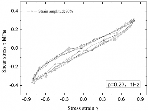
(b) Stress-strain hysteresis curves of MPR-SR I at the strain amplitudes of 80%
Figure 16. Shear stress-strain curves of MPR-SR I at large strain amplitudes
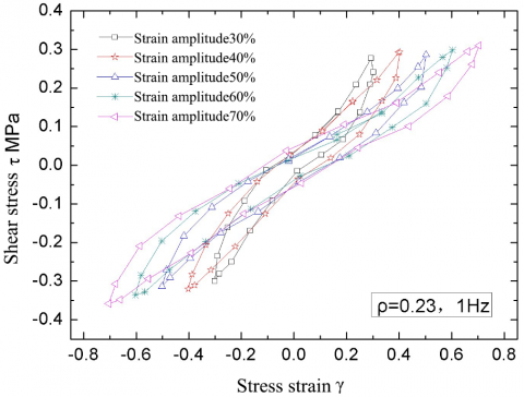
The next step is to test the resistance of the MPR/SR composite to ultimate shear deformation. For this purpose, MPR-SR I were applied shear load with stepwise increase in strain amplitude. Figure 16(a) offers the hysteresis curves of MPR-SR I at the strain amplitudes of 30%, 40%, 50%, 60% and 70%. It can be observed that the specimen could fully recover from the strain amplitude of 70%, revealing the stable elastic performance of the specimen. When the strain further increased to 80% (Figure 16(b)), the AUHC gradually decreased with the growth in cycle number, strain degradation started to appear, and the specimen had obvious residual deformation after unloading. Hence, the recoverable ultimate deformation of the specimen was about 80%. This means the MPR/SR has a strong resistance to shear damages in the directions other than the punching direction.
According to the results of the above compression and share tests, the MPR/SR composite has relatively high bearing capacity and large compression modulus, under the compressive load in the punching direction. However, the shear modulus of the composite is relatively low in the other directions.
Table 4 lists the single-cycle secant moduli and equivalent damping ratios of MPR-SRs I, II and III under the loading frequency of 1Hz and the strain amplitude of 20%. The data show that the equivalent damping ratio of the MPR-SR composite under compression is smaller than that under shear deformation, and the secant modulus of the composite under compressive deformation is more than twice that under shear deformation. These results are favorable for developing a three-way SI device that withstands the vertical load of structures.
After the completion of all tests, each specimen was subjected to a failure test with large strain amplitude in the compression and shear directions. The recoverable ultimate deformations under compression and shear loads of each specimen were observed. The observations show that the MPR-SR composite could recover from the ultimate compressive deformation of 40% and the ultimate shear deformation of 80%.
Table 4. Secant moduli and equivalent damping ratios of specimens under compressive and shear loads
|
Strain amplitude 20%, 1Hz |
MPR-SR I (Molding density: 0.23) |
MPR-SR II (Molding density: 0.25) |
MPR-SR III (Molding density: 0.27) |
|||
|
Secant modulus |
Equivalent damping ratio |
Secant modulus |
Equivalent damping ratio |
Secant modulus |
Equivalent damping ratio |
|
|
Compression |
3.527 |
0.0289 |
4.561 |
0.0294 |
5.596 |
0.0385 |
|
Shear |
1.043 |
0.1153 |
1.2683 |
0.114 |
1.33 |
0.1168 |
This paper prepares MPR-SR specimens of different molding densities, and explores their compressive and shear hysteretic behaviors under quasi-static and dynamic loads, respectively. Several tests were carried out to reflect how these behaviors are affected by load amplitude, cycle count, loading frequency and molding density. The mechanical properties and damping features between the specimens were compared and analyzed in details. The main conclusions are as follows:
(1) When subjected to compressive deformation in the punching direction, the MPR-SR composite carries obvious features of strain hardening in its stress-strain curve, revealing a certain capacity for hysteretic energy dissipation; the cycle number and loading frequency have no significant impact on the compressive stress-strain hysteretic behavior of the composite; under the same strain amplitude, the higher the molding density, the greater the secant modulus and recoverability, and the larger the equivalent damping ratio.
(2) When subjected to shear deformation in the punching direction, the MPR-SR composite exhibits no obvious features of strain hardening in its stress-strain curve, showing a good energy dissipation ability; the cycle number and loading frequency have no impact on the shear stress-strain hysteretic behavior of the composite; under the same strain amplitude, the higher the molding density, the greater the secant modulus and the equivalent damping ratio; the shear stress-strain hysteretic behaviors of the composite are basically the same in the two directions (OX and OY) perpendicular to the punching direction, i.e. the composite enjoys similar shear performance in the two directions.
(3) The equivalent damping ratio of the MPR-SR composite under compression is smaller than that under shear deformation, and the secant modulus of the composite under compressive deformation is more than twice that under shear deformation. These features are favorable for developing a three-way SI device that withstands the vertical load of structures.
This work is supported by Heilongjiang Provincial Natural Science Foundation for the general project “Seismic Failure Modes of Frame-Shear Structures in Energy Dissipators Based on Metal Pseudo-Rubber/ Silicone Rubber” (Grant No.: E201401), and by the University Students Innovation and Entrepreneurship Training Program of Heilongjiang Province for the project “Mechanical Experiment and Seismic Isolation Analysis of Energy Dissipators Based on Metal Pseudo-Rubber/ Silicone Rubber” (Grant No.: 201910225245).
[1] Cetin, H., Aydin, E., Ozturk, B. (2019). Optimal design and distribution of viscous dampers for shear building structures under seismic excitations. Frontiers in Built Environment, 5: 90. https://doi.org/10.3389/fbuil.2019.00090
[2] Taheri, A., Hosseini, M., Moghadam, A.S. (2018). Creation of innovative earthquake resistant steel buildings by dividing the structure into inner and outer parts having interaction by hysteretic dampers. Journal of Vibroengineering, 20(1): 477-493. https://doi.org/10.21595/jve.2017.19194
[3] Chegodaev, D.E. (2000). Design of Metal Rubber Components. Beijing: National Defence Industry Press.
[4] Li, H., Mao, C.X. (2007). Experimental investigation of earthquake response reduction of buildings with added two types of SMA passive energy dissipation devices. Earthquake Engineering and Engineering Vibration, 23(1): 133-139.
[5] Kou, H., Liu, G., Yang, J., Bai, H. (2006). Microstructure and mechanical properties of stainless steel wires used for metal rubber. Journal of Aeronautical materials, 26(4): 24-28.
[6] Jiang, H., Zhang, R., Xia, Y. (2006). Stationary dynamic characteristics analysis of new squeezed film damper. Chinese Journal of Mechanical Engineering (English Edition), 19(3): 442-445. http://dx.doi.org/10.3901/CJME.2006.03.442
[7] Li, Y., Li, X., Huang, X. (2011). Research on factors influencing the mechanical properties of metallic rubber. Mechanics of Composite Materials, 47(5): 571-580. https://doi.org/10.1007/s11029-011-9235-5
[8] Mazzolani, F.M., Mandara, A. (2002). Modern trends in the use of special metals for the improvement of historical and monumental structures. Engineering Structures, 24(7): 843-856. https://doi.org/10.1016/S0141-0296(02)00023-8
[9] Zou, G.P., Liu, Z., Liu, S., Cheng, H. (2016). Finite element simulation of metal rubber damper random vibration. Chinese Journal of Mechanical Engineering, 14(27): 1960-1963. https://doi.org/10.3969/j.issn.1004-132X.2016.14.020
[10] Ma, Y., Gao, D., Hong, J. (2014). Investigation on the effect of dimension on the compression mechanics of metal rubber. ASME Turbo Expo 2014: Turbine Technical Conference and Exposition, Düsseldorf, Germany. https://doi.org/10.1115/GT2014-25373
[11] Cao, F., Bai, H., Li, D., Ren, G., Li, G. (2016). A constitutive model of metal rubber for hysteresis characteristics based on a meso-mechanical method. Rare Metal Materials & Engineering, 45(1): 1-6. https://doi.org/10.1016/S1875-5372(16)30035-2
[12] Balaji, P.S., Moussa, L., Rahman, M.E., Vuia, L.T. (2015). Experimental investigation on the hysteresis behavior of the wire rope isolators. Journal of Mechanical Science and Technology, 29(4): 1527-1536. https://doi.org/10.1007/s12206-015-0325-5
[13] Zhang, D., Scarpa, F., Ma, Y., Hong, J., Mahadik, Y. (2014). Dynamic mechanical behavior of nickel-based superalloy metal rubber. Materials & Design (1980-2015), 56: 69-77. https://doi.org/10.1016/j.matdes.2013.10.088
[14] Ismail, M., Ikhouane, F., Rodellar, J. (2009). The hysteresis Bouc-Wen model, a survey. Archives of Computational Methods in Engineering, 16(2): 161-188. https://doi.org/10.1007/s11831-009-9031-8
[15] Rodney, D., Gadot, B., Martinez, O.R., Du Roscoat, S.R., Orgéas, L. (2016). Reversible dilatancy in entangled single-wire materials. Nature materials, 15(1): 72-77. https://doi.org/10.1038/nmat4429
[16] San Andrés, L., Abraham Chirathadam, T. (2013). Performance characteristics of metal mesh foil bearings: predictions versus measurements. Journal of Engineering for Gas Turbines and Power, 135(12): 122503-122511. https://doi.org/10.1115/1.4025146
[17] Feng, K., Liu, W., Zhang, Z., Zhang, T. (2016). Theoretical model of flexure pivot tilting pad gas bearings with metal mesh dampers in parallel. Tribology International, 94: 26-38. https://doi.org/10.1016/j.triboint.2015.08.002
[18] Ma, Y., Zhang, Q., Zhang, D., Scarpa, F., Gao, D., Hong, J. (2017). Size-dependent mechanical behavior and boundary layer effects in entangled metallic wire material systems. Journal of Materials Science, 52(7): 3741-3756. https://doi.org/10.1007/s10853-016-0478-3
[19] Tan, Q., He, G. (2013). Stretching behaviors of entangled materials with spiral wire structure. Materials & Design, 46: 61-65. https://doi.org/10.1016/j.matdes.2012.10.003
[20] Xia, Y., Jiang, H.Y., Ao, H.R., Li, G. (2002). Research on the effect of wire distribution on the characteristics of metal rubber element. China Mechanical Engineering, 13(10): 880-883.
[21] Zhang, D., Scarpa, F., Ma, Y., Boba, K., Hong, J., Lu, H. (2013). Compression mechanics of nickel-based superalloy metal rubber. Materials Science and Engineering: A, 580: 305-312. https://doi.org/10.1016/j.msea.2013.05.064
[22] Li, S., Mao, C., Li, H., Zhao, Y. (2011). Mechanical properties and theoretical modeling of self-centering shape memory alloy pseudo-rubber. Smart Materials and Structures, 20(11): 271-278.
[23] Gadot, B., Martinez, O. R., Du Roscoat, S. R., Bouvard, D., Rodney, D., Orgéas, L. (2015). Entangled single-wire NiTi material: A porous metal with tunable superelastic and shape memory properties. Acta Materialia, 96: 311-323. https://doi.org/10.1016/j.actamat.2015.06.018
[24] Ertas, B., Luo, H., Hallman, D. (2009). Dynamic characteristics of shape memory alloy metal mesh dampers. In 50th AIAA/ASME/ASCE/AHS/ASC Structures, Structural Dynamics, and Materials Conference, Palm Springs, California. https://doi.org/10.2514/6.2009-2521
[25] Ma, Y., Liang, Z., Wang, H., Zhang, D., Hong, J. (2013). Theoretical and experimental steady-state rotordynamics of an adaptive air film damper with metal rubber. Journal of Sound & Vibration, 332(22): 5710-5726. https://doi.org/10.1016/j.jsv.2013.06.002
[26] Ertas, B.H., Al-Khateeb, E., Vance, J.M. (2003). Rotordynamic bearing dampers for cryogenic rocket engine turbopumps. Journal of propulsion and power, 19(4): 674-682. https://doi.org/10.2514/2.6157
[27] Zhang, D.Y., Xia, Y., Zhang, Q.C., Ma, Y.H., Hong, J. (2018). Researches on metal rubber mechanics properties in retrospect and prospect. Journal of Aerospace Power, 33(6): 1432-1445.
[28] Wang, Q., Cheng, M., He, G., Zhang, X. (2015). Surface modification of porous titanium with microarc oxidation and its effects on osteogenesis activity in vitro. Journal of Nanomaterials, 16(1): 30.