Hamza Bahri | Adelghani Harrag*
OPEN ACCESS
This paper outlines an innovative way in the assessment of proton exchange membrane fuel cell maximum power point tracking using Matlab/Stateflow implementation of variable step size version of perturb and observe and incremental conductance maximum power point tracking algorithms. In this study, the perturb and observe as well as the incremental conductance maximum power point tracking controllers have been completely implemented as Matlab/Stateflow models having as inputs: cell voltage, cell current and the variable step size; the model's output is the pulse width modulation ratio to drive the DC-DC boost converter for supplying the maximum power available from the 7kW proton exchange membrane fuel cell to a 50W resistive load. Simulation obtained results under different test scenarios prove the effectiveness of the proposed Matlab/Stateflow maximum power point tracking models that can provide accurate results and giving a strong tool to test and validate maximum power point tracking controllers.
fuel cell, PEMFC, MPPT, perturb and observe, incremental conductance, Matlab/Stateflow
The world faces several difficult challenges, especially with the increase in demographic growth, which could reach nine billion in the early fifties of this century. This population increase is accompanied by a significant increase in the percentage of electricity consumption, which is one of the most important requirements of life. Fossil fuels have been, to this day, the main source of electric power generation. However, these sources cause an imbalance in the environmental balance due to the exacerbation of global warming. Therefore, it has become imperative to search for alternative renewable energy sources and find new ways to use energy more efficiently. It can be said that this era is the era of renewable energies [1].
Technological development is accelerating daily, which has positively affected the development and improvement of the efficiency of renewable energy sources. As a result, its contributions to the production of electrical energy have increased. For example, in some Western European countries, its contribution has reached 20-30% of the total energy consumption. Therefore, with the achievement of such results in the production of clean energy, the research has begun to raise the production capacity to cover most of our demand in the medium and long term. However, renewable energy sources such as solar and wind power suffer from a drawback that must be taken into account, which is their intermittent nature. In fact, we may record a lack or absence of power produced that may coincide with the moment of the high demand for it from the loads. As a result, it is necessary to apply modern technologies to ensure the storage of energy in order to exploit it in times of inability to supply energy from these sources [1, 2].
In this context, batteries emerge as a primary energy storage solution, as they are always found in all systems that include PV and wind energy sources, both for stand-alone and grid-connected systems. However, energy storage using batteries does not allow for long periods of power supply. Hydrogen and fuel cells play an important role in that fuel cells are highly efficient sources and hydrogen is a well-known energy carrier. Hydrogen can be produced in several ways as it is one of the main elements in all components of materials, and perhaps the use of electrolysis of water is one of the most important ways to produce hydrogen by using photovoltaic system to feed the electrolyzer. The hydrogen produced is stored for later use during low production periods by fuel cells [1, 3, 4].
Fuel cells can be defined as a thermodynamic system that converts the energy contained in hydrogen and oxygen into electrical energy under oxidation and reduction reactions. These reactions are located in two electrodes; one named anode is the center of the hydrogen (H2) oxidation reaction, while the second named the cathode is the center of oxygen (O2) reduction reaction. The anode and cathode is separated by a dense electrolyte, a material that ideally is an ionic conductor but electronic insulator. Unlike batteries, fuel cells are power sources that use hydrogen and oxygen as reactants and work as long as these gases are supplied to the both electrodes. Although there are several types of fuel cells on the market, they offer common features as shown below [5-8]:
Among the six types of fuel cells available in the market, the proton exchange membrane fuel cell (PEMFC) appears as one of the most widely used types in several applications especially in the stationary and portable. This is due to its distinct characteristics such as: high power density, low weight, pollutant free operation and no noise. On the other hand, a relevant aspect is their low temperature of operation (typically 60–80℃), which allows fast starting times [9-12].
The output power of the PEM fuel cell shows a non-linear power-current (P-I) characteristic that its maximum power point (MPP) differs with changes in many parameters such as: temperature, partial gases pressures, membrane water content, density current, reactants humidity level, gas speed and stoichiometry. Therefore, the operation of a fuel cell in applications with varying load demands without power electronics controlled by a maximum power point tracking (MPPT) algorithm to adjust the operating point on the V/I curve corresponding to the actual power demand is impossible [13-15].
Over the past decade, the technique of the maximum power point tracking (MPPT) controller for fuel cell power systems has remarkable development [16, 17]. Perturb and Observation (P&O) and Incremental Conductance (IC) MPPTs are considered the most used algorithms for their simplicity and easy implementation:
Karami et al. [18] introduced a new hybrid technique of MPPT to extract the MPP, which includes the use of the conventional P&O driving a buck converter with a fuel flow rate controller. From results of simulation, the hybrid technique proposed extracts with high efficiency the MPP from the FC at various fuel flow rates. In addition, this proposed technique avoids overheating, allowing the formation of excess water, thereby protecting the fuel cell from deterioration of the mechanical structure and membrane.
Kiruthiga et al. [19] designed a P&O based MPPT for solar photovoltaic system along with interleaved boost converter and boost converter is employed for fuel cell. The hybrid photovoltaic-Fuel cell based system has been studied under various load conditions for the mitigation of voltage sag in the power systems using a PI controller. The proposed approach has been simulated using Matlab/Simulink environment considering different load conditions.
Harrag and Messalti [21] introduced a technique of MPPT controller for the PEMFC system called variable step size IC MPPT. To validate this technique, it applied to PEMFC of 7kW used to feed resistive load through DC-DC boost converter. Under variable operating conditions of pressures and temperatures, the whole system has been simulated. The results obtained confirm the high performances of the proposed MPPT compared to the fixed step size IC MPPT concerning dynamic and static performances leading to a gross optimization of the system output power.
Harrag and Bahri [22] proposed a neural network variable step size IC-based MPPT controller for the PEMFC power system. Using the Matlab/Simulink environment, the effectiveness of the proposed technique has been successfully demonstrated. The results obtained demonstrate the superiority of the technique of neural network IC-based variable step size MPPT compared to the conventional fixed step size in terms of dynamic and static performances. In addition, the proposed MPPT technique has the advantage of better reducing voltage and current ripple, which positively affects the PEMFC in terms of improving efficiency and increasing its life.
To extract the maximum output power from the PEMFC source, Harrag and Messalti [23] introduced a variable step size fuzzy based MPPT controller. To prove the technique proposed, the authors compared it with conventional fixed step size IC, the variable step size IC, the fuzzy auto-scaled variable step size IC. The simulation results show that the proposed MPPT controller has high performances in many aspects such as dynamic and static performances compared to other techniques introduced.
In this work, an innovative way in the assessment of PEM fuel cell MPPT using Matlab/Stateflow implementation of variable step size version of P&O and IC MPPTs is presented and investigated. The P&O as well as the IC MPPTs are completely implemented as Matlab/Stateflow models having as inputs: cell voltage, cell current and the variable step size; the model's output is the PWM ratio used to drive the DC-DC boost converter for supplying the maximum power available from the used 7kW PEM fuel cell to a 50W resistive load. Simulation results using different test scenarios show the effectiveness of the proposed Matlab/Stateflow MPPT models that can provide accurate results and giving a strong tool to test and validate MPPTs.
This paper is presented as follows. In Section 2, the PEMFC modelling, the used MPPT algorithms and the DC/DC boost converter are detailed; while Section 3 presents the P&O as well as the IC MPPTs. The proposed Matlab/Stateflow P&O and IC MPPTs models are detailed in Section 4. The results of simulation and discussions are presented in Section 5. Section 6 present the essential conclusions of our study.
PEMFC is an energy conversion system (Figure 1), which generates electricity and heat without any polluting emissions to the environment [24].
Figure 1. PEMFC operating strategy
PEM fuel cell operates under the following reactions:
At anode: The oxidation of hydrogen occurs as follow:
$\mathrm{H}_{2} \rightarrow 2 \mathrm{H}^{+}+2 \mathrm{e}^{-}$ (1)
At anode: The reduction of oxygen occurs as follow:
$\mathrm{O}_{2}+4 \mathrm{e}^{-} \rightarrow 2 \mathrm{O}^{-2}$ (2)
The total H2/O2 PEMFC reaction is:
$\mathrm{H}_{2}+\frac{1}{2} \mathrm{O}_{2} \rightarrow \mathrm{H}_{2} \mathrm{O}($ Water $)+$ Electricity $+$ Heat (3)
The output voltage can be presented by the below following expression for each cell:
$\mathrm{V}_{\mathrm{FC}}=\mathrm{E}_{\mathrm{nernst}}-\mathrm{V}_{\mathrm{act}}-\mathrm{V}_{\mathrm{ohmic}}-\mathrm{V}_{\mathrm{conc}}$ (4)
where, Enernst is the Nernst voltage approximated by empirical expression of Eq. (5) [25, 26]:
$\begin{aligned} \mathrm{E}_{\text {nernst }}=1.229-& 8.5 \times 10^{-4}(\mathrm{~T}-298.15) \\ &+4.385 \\ & \times 10^{-5} \mathrm{~T}\left(\ln \left(\mathrm{P}_{\mathrm{H}_{2}}\right)\right.\\ &\left.+0.5 \times \ln \left(\mathrm{P}_{\mathrm{O}_{2}}\right)\right) \end{aligned}$ (5)
where, $\mathrm{T}_{F C}$ is the temperature; PO2 and PH2 are the oxygen and hydrogen pressure respectively.
The activation voltage loss Vact is approximated by empirical expression of Eq. (6):
$\mathrm{V}_{\text {act }}=\delta_{1}+\delta_{2} \cdot \mathrm{T}_{F C}+\delta_{3} \cdot \mathrm{T} \cdot \ln \left(\mathrm{C}_{\mathrm{O} 2}\right)+\delta_{4} \cdot \mathrm{T}_{F C}$$\cdot \ln \left(\mathrm{i}_{\mathrm{FC}}\right)$ (6)
where, iFC is the cell current; CO2 is the oxygen’s concentration; and $\delta_{i}(i=1$ to 4$)$ are parametric coefficients for each cell model.
The ohmic voltage loss Vohmic is given by:
$\mathrm{V}_{\text {ohmic }}=\left(\mathrm{R}_{\mathrm{M}}+\mathrm{R}_{\mathrm{C}}\right) \mathrm{i}_{\mathrm{FC}}$ (7)
where, iFC is the cell current; and RM and RC are the membrane and contact resistances, respectively.
The concentration voltage loss $V_{\text {conc }}$ is defined by:
$\mathrm{V}_{\mathrm{conc}}=-\mathrm{b} \cdot \ln \left(1-\frac{\mathrm{i}_{\mathrm{FC}} / \mathrm{A}}{\mathrm{I}_{\max }}\right)$ (8)
where, iFC is the cell current; A is the is cell active area; $\mathrm{I}_{\max }$ is the maximum current density; and b is the concentration loss constant.
In the control of PEMFC, there are three control strategies: the first relates to the output power when the presence of variation in the load requirements. The second control strategies is relates to the parameters of reactant gases (hydrogen and gases), as well as temperature and water management. While the third is relates to the maximum power and efficiency of the PEMFC. In this work, we concentrate on the control of the PEMFC output power.
From the overall output voltage of PEMFC, we can be seen that voltage source shows a highly nonlinear reliance to operating conditions such as partial pressure of reactant gases, temperature, membrane water content and electric current. Due to this nonlinear, multi-parameter dependent conduct, precisely controlled conditions must be guaranteed for proper operation using an MPPT technique to operate around an optimal operating point corresponding to the maximum power generated by the PEMFC source. This is possible by adapting constantly the PWM ratio of the boost converter that acts as adaptive impedance.
3.1 P&O MPPT
P&O MPPT includes perturbation of the operating current based on a comparison of the generated power to track the MPP. At specified PEMFC current, the required power is the solution of the nonlinear equation given by dP/dI = 0 [27].
3.2 IC MPPT
The IC algorithm concentrates directly on power changes. The both current and voltage of the PEMFC are employed to calculate the conductance and the incremental conductance [28]. The main equations of this technique are presented as follows:
$\frac{\mathrm{dP}}{\mathrm{dI}}=\frac{\mathrm{d}(\mathrm{I} . \mathrm{V})}{\mathrm{dI}}=\mathrm{V}+\mathrm{I} \frac{\mathrm{dV}}{\mathrm{dI}}=0$ (9)
Eq. (9) can be rewritten as:
$\frac{\mathrm{dV}}{\mathrm{dI}}=-\frac{\mathrm{V}}{\mathrm{I}}$ at MPP (10)
$\frac{d V}{d I}>-\frac{V}{I}$ at the left of MPP (11)
$\frac{\mathrm{dV}}{\mathrm{dI}}<-\frac{\mathrm{V}}{\mathrm{I}}$ at the right of MPP (12)
Matlab/Stateflow is employed in conjunction with Simulink, and it is a graphical design and development tool for control and supervisory logic. It provides obvious and brief descriptions of complex system behaviour using finite state machine theory, flow diagram notations, and state-transition diagrams. In this study, the P&O as well as the IC MPPTs discussed in section 3 have been completely implemented using Matlab/Stateflow models. The implemented models have as inputs: cell voltage, cell current and the variable step size; while the model's output is the PWM ratio to drive the DC-DC boost converter for supplying the maximum power available from the PEM fuel cell to the load.
In this par, we will analyze the main results of simulation by using Matlab/Simulink environment. The whole system implemented in Matlab/Simulink is composed of 7 kW PEMFC used to supply a 50 W resistive load through a boost converter controlled using the implemented stateflow MPPT controllers. Table 1 and Table 2 give the PEMFC and the DC/DC boost converter parameters respectively.
Table 1. PEMFC parameters
|
Parameter |
Value |
|
Maximum Output Power at MPP (W) |
7000 |
|
Cell open circuit voltage (V) |
1.29 |
|
Number of cells |
50 |
|
Surface of Cell active (cm2) |
200 |
|
Partial pressure of $\mathrm{H}_{2}$ (bar) |
2.6 |
|
Partial pressure of $\mathrm{O}_{2}$ (bar) |
0.3 |
Table 2. Boost converter parameters
|
Parameters |
Value |
|
Inductance (mH) |
5 |
|
Capacity (µF) |
1000 |
|
Switching frequency Fs (KHz) |
10 |
|
Resistive Load (Ω) |
50 |
|
Vg (nominal voltage (V) |
47 |
The PEMFC power source developed model has been employed to analyze the implemented stateflow models performances considering:
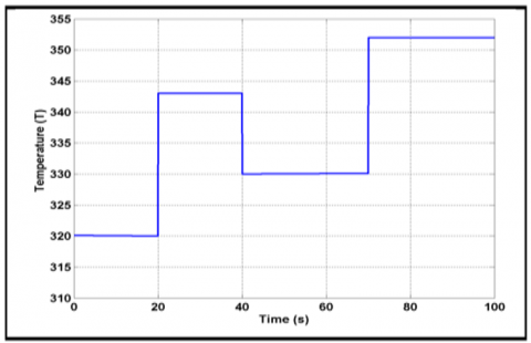
Figures 2.a and 2.b illustrate the test patterns used for temperature and hydrogen pressure variations, respectively.
(a)
(b)
Figure 2. a) Variation of temperature, b) Variation of Pressure
5.1 PEM Fuel Cell temperature variation
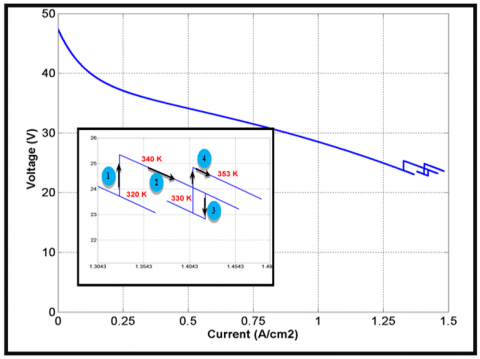
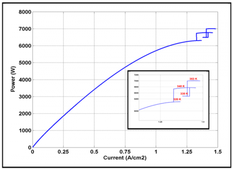
In this case we keep the hydrogen pressure fixed while changing the temperature according to the pattern test shown by Figure 2.a. Figures 3 and 4 show the PEM fuel cell characteristics (V-I and P-I) obtained using the developed P&O and IC stateflow models.
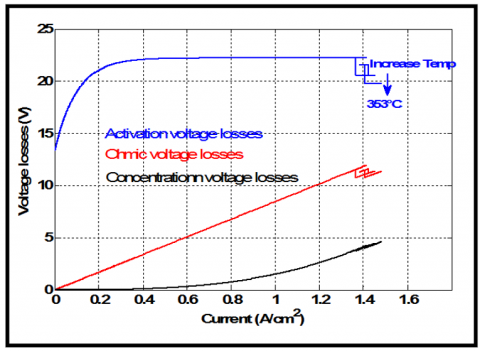
From Figures 3 and 4, we can see that the maximum power 7kW is reached at the operating temperature of 353K. On the other hand, the PEM fuel cell characteristics are sensitive to temperature variation. The increase in temperature during operation accelerates the chemical reaction inside the fuel cell, and decreases the voltage losses (activation and ohmic losses) which are the most affected. On the contrary, the concentration losses are less affected. Therefore the voltage and power produced by the fuel cell increase following the temperature increase as shown in Figure 5.
(a)
(b)
Figure 3. PEMFC characteristics under variation temperature using P&O Stateflow MPPT
(a)
(b)
Figure 4. PEMFC characteristics under variation temperature: using IC Stateflow MPPT
(a)
(b)
Figure 5. PEMFC voltage losses: a) with P&O, b) with IC
5.2 PEM Fuel Cell pressure variation
In this case we keep the temperature fixed while changing the hydrogen pressure according to the pattern test shown by Figure 2.b. Figures 6 and 7 show the PEM fuel cell characteristics (V-I and P-I) obtained using the developed P&O and IC stateflow models under the defined hydrogen pressure changes. In case of hydrogen pressure increase, the power increases. The maximum power delivered is 7kW corresponding to a hydrogen pressure of 2.6bar.
(a)
(b)
Figure 6. PEMFC characteristics under pressure variation using Stateflow P&O MPPT
(a)
(b)
Figure 7. PEMFC characteristics under pressure variation using Stateflow IC MPPT
This paper presents an innovative way in the assessment of PEM fuel cell MPPT using Matlab/Stateflow implementation. The P&O as well as the IC MPPTs are completely implemented as Matlab/Stateflow models having as inputs: cell voltage, cell current and the variable step size; the model's output is the PWM ratio used to drive the DC-DC boost converter for supplying the maximum power available from the used 7kW PEM fuel cell to a 50W resistive load. Simulation results using different test scenarios show the effectiveness of the proposed Matlab/Stateflow MPPT models that can provide accurate results and giving a strong tool to test and validate different kind of fuel cell MPPTs. As future works, the model will be validated firstly using the hardware in the loop mode using the STM32F4 board and secondly in an autonomous mode.
The Algerian Ministry of Higher Education and Scientific Research supported this research (Research PRFU Project reference A01L07UN190120180005).
[1] Moya, X., Muñoz-Rojas, D. (2016). Materials for Sustainable Energy Applications - Conversion, Storage, Transmission, and Consumption. Pan Stanford Publishing, Taylor & Francis Group, Boca Raton.
[2] IRENA. (2018). Global Energy Transformation - A Roadmap to 2050. International Renewable Energy Agency.
[3] Staffell, I., Dodds, P.E. (2017). The role of hydrogen and fuel cells in future energy systems. H2FC SUPERGEN, London, UK.
[4] Ashrafi, M., Shams, M., Bozorgnezhad, A., Ahmadi, G. (2016). Simulation and experimental validation of droplet dynamics in microchannels of PEM fuel cells. Heat and Mass Transfer, 52(12): 2671-2686. https://doi.org/10.1007/s00231-016-1771-z
[5] Guilbert, D., N’Diaye, A., Gaillard, A., Djerdir, A. (2016). Fuel cell systems reliability and availability enhancement by developing a fast and efficient power switch open-circuit fault detection algorithm in interleaved DC/DC boost converter topologies. International Journal of Hydrogen Energy, 41(14): 15505-15517. https://doi.org/10.1016/j.ijhydene.2016.01.169
[6] Larminie, J., Dicks, A., McDonald, M.S. (2003). Fuel Cell Systems Explained. Vol. 2. Wiley Chichester. https://doi.org/10.1002/9781118706992
[7] Bicer, Y., Dincer, I., Aydin, M. (2016). Maximizing performance of fuel cell using artificial neural network approach for smart grid applications. Energy, 116(1): 1205-1217. https://doi.org/10.1016/j.energy.2016.10.050
[8] Ashrafi, M., Shams, M. (2016). Effects of heterogeneous surface of gas diffusion layers on droplet transport in microchannels of PEM fuel cells. International Journal of Hydrogen Energy 41(3): 1974-1989. https://doi.org/10.1016/j.ijhydene.2015.11.096
[9] Kunusch, C., Puleston, P., Mayosky, M. (2012). Sliding-Mode Control of PEM Fuel Cells, Advances in Industrial Control. Springer-Verlag London Limited. https://doi.org/10.1007/978-1-4471-2431-3
[10] Spiegel, C. (2008). PEM Modeling and Simulation Using Matlab. Burlington, MA: Academic Press.
[11] Becherif, M., Hissel, D. (2010). MPPT of a PEMFC based on air supply control of the motocompressor group. International Journal of Hydrogen Energy, 35(22): 12521-12530. https://doi.org/10.1016/j.ijhydene.2010.06.094
[12] Ashrafi, M., Shams, M. (2017). The effects of flow-field orientation on water management in PEM fuel cells with serpentine channels. Applied Energy, 208: 1083-1096. https://doi.org/10.1016/j.apenergy.2017.09.044
[13] Tabanjat, A., Becherif, M., Hissel, D., Ramadan, H.S. (2018). Energy management hypothesis for hybrid power system of H2/WT/PV/GMT via AI techniques. International Journal of Hydrogen Energy, 43(6): 3527-3541. https://doi.org/10.1016/j.ijhydene.2017.06.085
[14] Fathabadi, H. (2016). Novel highly accurate universal maximum power point tracker for maximum power extraction from hybrid fuel cell/PV/wind power generation systems. Energy, 116: 402-416. https://doi.org/10.1016/j.energy.2016.09.095
[15] Ashrafi, M., Kanani, H., Shams, M. (2018). Numerical and experimental study of two-phase flow uniformity in channels of parallel PEM fuel cells with modified Z-type flow-fields. Energy, 147(C): 317-28. https://doi.org/10.1016/j.energy.2018.01.064
[16] Habib, M., Khouch, F., Harrag, A. (2017). GA-based robust LQR controller for interleaved boost DC–D converter improving fuel cell voltage regulation. Electric Power Systems Research, 152: 438-456. https://doi.org/10.1016/j.epsr.2017.08.004
[17] Avanaki, I.N., Sarvi, M. (2016). A new maximum power point tracking method for PEM fuel cells based on water cycle algorithm. J Renew Energy Environ, 3(1): 35-42.
[18] Karami, N., Outbib, R., Moubayed, N. (2012). Fuel flow control of a PEM fuel cell with MPPT. 2012 IEEE International Symposium on Intelligent Control, pp. 289-294. https://doi.org/10.1109/ISIC.2012.6398246
[19] Kiruthiga, K., Dyaneswaran, A., Kavitha, B., Prakash, R.A. (2014). A grid connected hybrid fuel cell-PO based MPPT for partially shaded solar PV system. International Journal of P2P Network Trends and Technology, 4(2): 42-46.
[20] Harrag, A., Bahri, H., Messalti, S. (2016). Variable step size P&O MPPT algorithm for fuel cell energy system. In: 2nd International Conference on Advances in Mechanical Engineering (ICAME'2016), Istanbul, Turkey, 10-13 May.
[21] Harrag, A., Messalti, S. (2017) Variable step size IC MPPT controller for PEMFC power system improving static and dynamic performances. Fuel Cells, 17(6): 816-824. https://doi.org/10.1002/fuce.201700047
[22] Harrag, A., Bahri, H. (2017). Novel neural network IC-based variable step size fuel cell MPPT controller - performance, efficiency and lifetime improvement. International Journal on Hydrogen Energy 42(5): 3549-3563. https://doi.org/10.1016/j.ijhydene.2016.12.079
[23] Harrag, A., Messalti, S. (2018). How fuzzy logic can improve PEM fuel cell MPPT performances. International Journal on Hydrogen Energy, 43(1): 537-550. https://doi.org/10.1016/j.ijhydene.2017.04.093
[24] Gou, B., Na, W., Diong, B. (2010). Fuel Cells: Modeling, Control, and Applications. New York: CRC Press.
[25] Wang, C., Nehrir, M.H., Shaw, S.R. (2005). Dynamic models and model validation for PEMFC using electrical circuits. IEEE Transactions on Energy Conversion, 20(2): 442-451. https://doi.org/10.1109/TEC.2004.842357
[26] Saeed, W., Warkozek, G. (2015). Modeling and analysis of renewable PEM fuel cell system. Energy Procedia, 74: 87-101. https://doi.org/10.1016/j.egypro.2015.07.527
[27] Karami, N., El Khoury, L., Khoury, G., Moubayed, N. (2014). Comparative study between P&O and incremental conductance for fuel cell MPPT. International Conference on Renewable Energies for Developing Countries 2014, pp. 17-22. https://doi.org/10.1109/REDEC.2014.7038524
[28] Harrag, A., Bahri, H. (2016). IC-based variable step size MPPT controller for PEMFC power system-analysis and performance improvements. In: Proceedings International Symposium on Sustainable Hydrogen (ISSH2'2016), Alger, Algeria; 5-6 October.