Zamzami![]() | Akhyar Akhyar*
| Akhyar Akhyar*![]() | Suriadi
| Suriadi![]() | Sarwo Edhy Sofyan
| Sarwo Edhy Sofyan![]() | Agus Sasmito
| Agus Sasmito![]()
© 2026 The authors. This article is published by IIETA and is licensed under the CC BY 4.0 license (http://creativecommons.org/licenses/by/4.0/).
OPEN ACCESS
Gravitational water vortex hydro turbines (GWVHTs) have emerged as a promising renewable energy technology for ultra-low-head hydropower applications. Among the design parameters, the blade angle plays a critical role in governing vortex stability, flow structure, and turbine performance. This study numerically investigated the hydrodynamic response of a three-blade GWVHT featuring blade angles of 75°, 90°, and 105°. Transient computational fluid dynamics simulations were conducted using the realizable k–ε turbulence model with standard wall functions. The analysis focused on velocity distribution, air-core development, and pressure-gradient characteristics to identify the optimal blade configuration. The results indicate that the 90° blade angle provides the most balanced hydrodynamic performance, yielding a stable vortex structure, a compact air core, and a symmetric pressure field. Compared to the 75° configuration, the 90o angle increased the maximum flow velocity by 41.3% (to 4.376 m.s-1) and enhanced the suction-pressure reduction by 53.1% (to 3.154 Pa). Although the 105° blade angle produced the highest peak velocity (4.657 m.s-1) and pressure (5892.066 Pa), its performance was adversely affected by premature flow separation and pressure-field distortion. Consequently, the 90° blade angle was identified as the optimal configuration for improving vortex stability and promoting effective hydraulic energy extraction in GWVHT systems.
gravitational water vortex hydro turbine, blade angle, computational fluid dynamics, vortex stability, hydrodynamic performance
The transition to renewable energy represents a global imperative due to the environmental consequences of fossil fuel dependency [1]. As electricity is essential for modern activities, generation from sustainable sources is necessary. Hydropower plants (HPPs) effectively convert the potential energy of water into electrical energy [2]. Countries with abundant water resources, such as Indonesia, possess significant potential for developing hydropower, particularly through low-head systems [3]. In this context, the ultra-low-head gravitational water vortex turbine (GWVT) has emerged as an innovative technology, specifically for rivers or irrigation channels characterized by minimal current velocities and low water heads [4, 5]. Optimising these turbines is crucial to enhance the exploitation of sustainable water resources and support future energy availability [6].
Previous studies have investigated various methods to improve vortex turbine efficiency through experimental and numerical approaches. Computational fluid dynamics (CFD) serves as an effective tool for this purpose by providing detailed analysis of fluid flow behavior and turbulence around hydraulic structures [7]. In vortex turbine applications, CFD is used to model flow patterns, predict velocity and pressure distributions, and evaluate the impact of geometry variations on performance [8-10]. This numerical approach allows for the efficient testing of numerous scenarios, thereby reducing the costs and time associated with physical prototyping [11-13]. Design parameters such as water head, basin geometry, and channel configurations are critical determinants of efficiency [14-17]. In this study, the outlet diameter ratio was set to 0.2 times the basin diameter, which falls within the optimal range (0.1–0.3) required to generate a stable vortex [18].
The efficiency of a GWVT is fundamentally determined by the interaction between secondary flow structures and runner geometry [19]. Recent studies indicate a significant correlation between blade angular positioning, vortex core stability, and energy conversion effectiveness [20, 21]. Maintaining a cohesive vortex structure is critical because hydrodynamic instability triggers substantial energy dissipation [22]. For instance, a 75° blade configuration often produces an unstable vortex with a fragmented velocity distribution and an excessively large air-core [23]. Such phenomena lead to premature flow separation and hydraulic losses, preventing the effective transfer of tangential momentum to the blades and resulting in suboptimal efficiency [24, 25]. Consequently, this study aims to conduct a detailed analysis of these flow characteristics to determine the optimal blade angle configuration for practical turbine design.
Water vortex turbines have attracted significant interest due to their ability to convert kinetic energy into electricity without requiring large dams or causing substantial environmental impact. Conceptually, these turbines harness the centrifugal force within a vortex system to rotate rotor blades [26]. This mechanism represents a promising solution for sustainable energy production, particularly in low or ultra-low head environments where traditional turbines are ineffective.
The GWVHT typically consists of an inlet channel, a circular basin with a bottom aperture, and a rotor connected to a vertical shaft [27, 28]. The system utilises natural flow to create a free-surface vortex, which lowers the central pressure and forms an air-core [29]. Energy conversion occurs as the mechanical energy from the rotating blades is transferred to an integrated generator.
The strength of the free-surface vortex directly determines turbine efficiency. In a free vortex, gravity is the primary force influencing flow dynamics. The free-surface vortex in a GWVHT comprises several distinct regions: the central air-core, the free vortex zone, the transition between the forced vortex and the boundary layer, and the near-wall region affected by friction [30, 31]. Therefore, optimising these regions is essential for maximising energy yield.
In this study, the CFD approach was employed to investigate the hydrodynamic behaviour of the turbine. The simulations were formulated based on the Navier–Stokes equations (Eqs. (1)-(4)) [32, 33].
$\frac{\partial V_r}{\partial r}+\frac{\partial V_z}{\partial z}+\frac{V_r}{r}=0$ (1)
$V_r \frac{\partial V_\theta}{\partial r}+V_z \frac{\partial V_\theta}{\partial z}-\frac{V_r V_\theta}{r}=v\left(\frac{\partial^2 V_\theta}{\partial r^2}+\frac{\partial V_\theta}{r \partial r}-\frac{V_\theta}{r^2}+\frac{\partial^2 V_\theta}{\partial z^2}\right)$ (2)
$\begin{aligned} V_r \frac{\partial V_r}{\partial r} & +V_z \frac{\partial V_r}{\partial z}-\frac{V_\theta^2}{r}+\frac{\partial \rho}{\rho \partial r} =v\left(\frac{\partial^2 V_r}{\partial r^2}+\frac{\partial V_r}{r \partial r}-\frac{V_r}{r^2}+\frac{\partial^2 V_r}{\partial z^2}\right)\end{aligned}$ (3)
$V_r \frac{\partial V_z}{\partial r}+V_z \frac{\partial V_z}{\partial z}+\frac{\partial \rho}{\rho \partial z}=g+v\left(\frac{\partial^2 V_z}{\partial r^2}+\frac{\partial V_z}{r \partial r}+\frac{\partial^2 V_r}{\partial z^2}\right)$ (4)
where, $V_r$ is the radial velocity, $V_z$ is axial velocity, $ V_\theta$ is the tangential velocity, $v$ is the kinematic viscosity, $\rho$ is the fluid density, and $g$ is gravitational acceleration.
Flow behaviour and rotational forces in a vortex turbine are described by the circulation parameter ($\Gamma$), which is expressed as:
$\Gamma=2 \pi r V_\theta$ (5)
where, $\Gamma$ is the circulation parameter (m2/s), $r$ represents the distance from the centre of rotation (m), and $V_\theta$ denotes the tangential velocity (m/s). The tangential velocity ($V_\theta$) within the vortex flow pattern is governed by the relationship between the radius and fluid viscosity. The value of $V_\theta$ at the basin inlet is evaluated using the continuity Eqs. (6) and (7):
$V_\theta=\frac{Q}{b h_{i n}}$ (6)
$\Gamma=\frac{2 \pi r Q}{b h_{i n}}$ (7)
where, $b$ denotes the width of the inlet channel and $h_{i n}$ represents the water depth at the inlet section.
Hydrodynamic investigations were performed using Ansys Fluent 19.2 to conduct transient simulations. Fluent was selected for its superior capability in resolving rotational flow and turbulence. The Volume of Fluid (VoF) model was employed to accurately track the air-water interface, which is critical for modeling the formation of the turbine's vortex air-core.
The turbine model featured a basin diameter of 1.5 m and a height of 1.38 m. The system comprised a single water inlet channel and an outlet area. The inlet channel dimensions were 1.8 m in length, 0.8 m in width, and 1.2 m in height, featuring a bend angle of 146°. The outlet area had a diameter of 0.75 m and a height of 0.5 m.
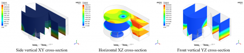
The turbine rotor consisted of three blades with a shaft diameter of 0.1 m. Individual blade dimensions were 0.35 m in height, 0.3 m in length, and 0.005 m in thickness. The primary variable in this study was the blade angle, which was tested at 75°, 90°, and 105° to evaluate the effect of orientation on energy capture efficiency, as shown in Figures 1 and 2.

Figure 1. Dimensions of the turbine with 3 blades

Figure 2. Dimensions of the 3-bladed turbine (75o, 90o, and 105o)
These specific blade angles were selected based on preliminary studies indicating that this range encompasses the peak efficiency point for vortex turbines with comparable diameter ratios. This selection provided two systematic extremes to facilitate a comparative analysis of water flow momentum [34]. While the 90o angle represents the standard perpendicular configuration relative to the axial flow, the +15° variations (75° and 105°) were chosen to examine performance sensitivity to moderate deviations from the standard configuration.
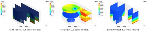
Domain discretisation was performed by importing the geometry into the Design Modeler, as shown in Figure 3. A tetrahedral mesh was selected for its effectiveness in handling complex geometries during fluid flow analysis. The mesh size was uniformly set to 5 mm. Before the simulations, mesh quality was evaluated based on skewness and orthogonality. The resulting grid achieved a maximum skewness of 0.2 and an average orthogonality exceeding 0.8, confirming that the elements were well-shaped for accurate flow-field prediction.


Figure 3. Vortex chamber meshing result
Simulations were executed using a pressure-based, double-precision solver in transient mode. The computational setup included a time-step size of 0.005 s, a total of 600 time steps, and a maximum of 50 iterations per time step. The angular velocity was set to 7.2 rad.s-1. The SIMPLE numerical scheme was applied with standard initialisation. Gravity was defined as 9.81 m s⁻² using an absolute velocity formulation. Furthermore, the VoF model was activated using two Eulerian phases (water-liquid and air) alongside an implicit body-force formulation.
The numerical domain was initialised according to the physical dimensions of the gravitational vortex system. Specific hydraulic diameters were utilized for the inlet channel and bottom aperture to facilitate natural free-surface vortex development. A velocity inlet was prescribed at the channel, while the bottom outlet was set to a pressure outlet condition to resolve air-core formation. The Realizable k-e turbulence model with standard wall functions was selected for its capability in resolving the mean flow of complex swirling fluids. While this model effectively captures macroscopic vortex profiles and centrifugal force distributions, it is acknowledged that isotropic eddy viscosity may have limitations in resolving highly anisotropic turbulence structures within the vortex core. Nonetheless, this framework provides a robust and computationally efficient balance for evaluating gravity-driven flow dynamics across varying blade configurations.
Boundary conditions for the simulation were established as follows: the inlet was defined as a velocity inlet with a constant water entry velocity of 1 m/s and a water volume fraction of 1, as shown in Figure 4. The outlet was set as a pressure outlet with a defined static pressure. All surfaces, including the top, sides, and floor, were designated as no-slip walls and treated as solid, impermeable boundaries.

Figure 4. Main components of the gravitational water vortex hydro turbine (GWVHT)
The solution at each time step reached convergence when all residuals fell below the specified threshold of 10-3. To ensure numerical stability, a maximum of 50 iterations per time step was permitted. A mesh sensitivity analysis was conducted to assess the influence of grid resolution on the numerical results (Figure 5). Blade tangential velocity was selected as the evaluation parameter due to its direct relevance to hydrodynamic performance. Five mesh resolutions were examined, ranging from 231,749 to 293,176 nodes. The tangential velocity increased from approximately 1.28 m.s-1 for the coarsest mesh to 1.29 m.s-1 for the finest mesh. The relative difference between the coarse and medium meshes was approximately 0.3%, while the variation between the medium mesh (252,944 nodes) and finer meshes was less than 0.2%.

Figure 5. Mesh sensitivity analysis showing the effect of the number of nodes on blade tangential velocity for the gravitational water vortex hydro turbine (GWVHT)
These results indicate that the solution reached mesh independence beyond approximately 250,000 nodes. Consequently, the mesh featuring 252,944 nodes was selected for subsequent simulations, as it provides an optimal balance between computational cost and numerical accuracy. Turbine efficiency was quantified based on the mechanical power output derived from torque and rotational speed. This output correlates directly with the CFD-predicted pressure differential across the blades.
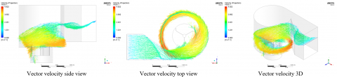
This study analyzed the hydrodynamic characteristics of the GWVHT by evaluating velocity distribution, water volume fraction, and pressure gradients across three blade configurations (75o, 90o, and 105o). These parameters exhibit a significant correlation. The stability of the generated vortex, quantified by the velocity distribution profile, governs the compactness of the air nucleus. This compactness subsequently dictates the differential pressure drop, which determines the overall energy extraction efficiency.
3.1 Velocity distribution
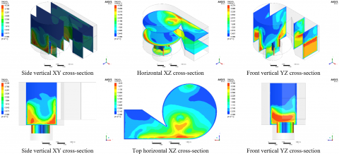
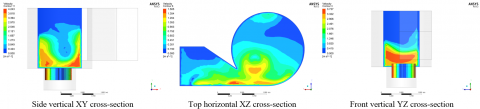
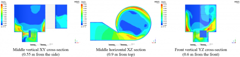
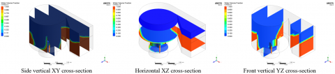
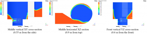
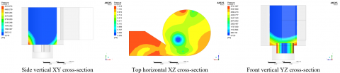
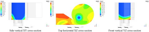
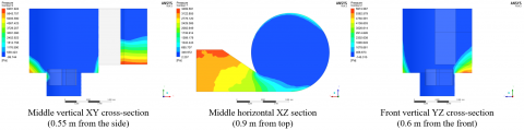
Figure 6 illustrates the velocity contours for the 75o blade angle, which represents a configuration with suboptimal efficiency. As water enters the zone above the turbine, the velocity distribution varies predominantly between 1.548 and 3.096 m.s-1. Despite initial vortex formation, the 75o angle generated low flow stability, as evidenced by the non-uniform velocity contours within the intake area. Rather than establishing a dense, symmetric vortex ring, the velocity pattern appeared fragmented, indicating an unstable vortex structure.
Figure 6. Velocity distribution of the vortex chamber at 75° blade angle (various cross-sections)
This instability was further corroborated by significant low-velocity regions (0 to 1.548 m.s‑1) across the peripheral and upstream sections of the intake area. The presence of these extensive low-velocity areas suggests the formation of recirculation zones where vortex momentum was not effectively developed. Such conditions contribute to substantial hydraulic losses. Consequently, the uneven velocity distribution signifies that tangential energy was not efficiently converted into mechanical energy. The inability to sustain a symmetric vortex directly limits the development of a stable pressure gradient along the blades, thereby reducing torque generation.
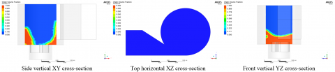
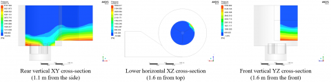
3.1.1 The 90° blade angle configuration
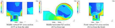
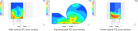
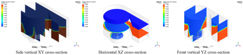
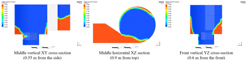
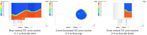
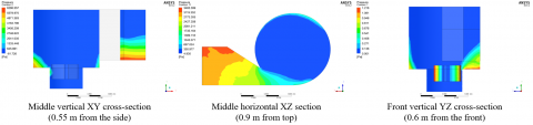
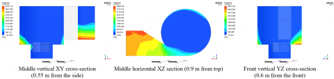
Figure 7 presents the velocity contours for the 90° blade angle, which was identified as the optimal design in this study. The contours confirm enhanced hydrodynamic performance characterized by stable and uniform flow. High-velocity regions, ranging from 3.063 to 4.376 m.s-1, appear dense and symmetrical within the intake area. This pattern evidences the formation of a stable, compact vortex ring, which is essential for minimizing hydraulic losses.
Figure 7. Velocity distribution of the vortex chamber at 90° blade angle (various cross-sections)
The maximum velocity reached 4.376 m.s-1, indicating an effective conversion of potential energy into kinetic energy prior to fluid interaction with the blades. Furthermore, the velocity distribution across the vertical cross-section remained balanced, with minimal low-velocity regions (0 to 0.438 m.s⁻¹) in the main flow zone. This stability was maintained through the lower section of the turbine. Such flow quality is fundamental to maximizing energy extraction, as it ensures an optimal pressure gradient along the blades and facilitates maximum fluid mass interaction.
3.1.2 The 105° blade angle configuration
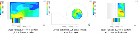
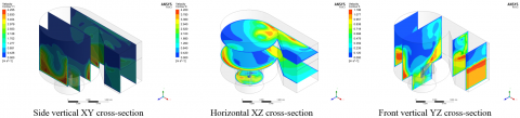
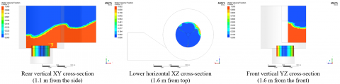
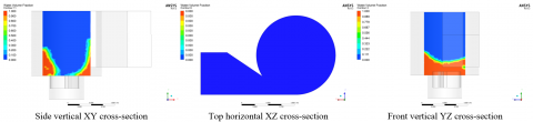
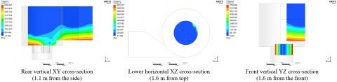
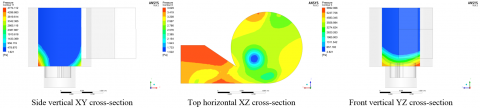
Figure 8 displays the velocity contours for the 105° blade angle, which resulted in significant performance degradation due to severe hydrodynamic instability. The velocity distribution around the intake area and upstream of the blades appeared diffuse. Although high peak velocities were recorded (3.260 to 4.657 m.s⁻¹), the flow failed to establish the compact vortex ring observed in the 90o configuration.
A critical phenomenon identified was premature flow separation, indicated by the substantial expansion of low-velocity areas (0 to 1.397 m.s⁻¹) along the intake area periphery. This separation resulted in the formation of large low-velocity pockets and an enlarged wake downstream of the blades. Consequently, the pressure pattern was distorted, increasing hydraulic losses as vortex energy was not effectively transferred to the rotor. The non-uniform and diffuse velocity contours signify an inability to maintain vortex compactness, which diminished the differential pressure gradient and lowered overall performance. These results confirm that the 105° configuration represents a suboptimal design.
Figure 8. Velocity distribution of the vortex chamber at 105° blade angle (various cross-sections)
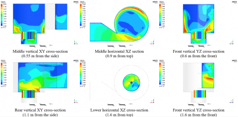
3.2 Water volume fraction distribution
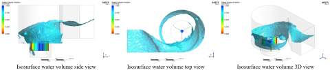
Analysis of the water volume fraction validated the velocity distribution results, demonstrating that vortex stability directly correlates with air-core geometry. The compactness of this air-core is critical, as a slender central region ensures maximum fluid mass interaction with the turbine blades.
3.2.1 The 75° blade angle configuration
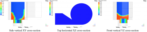
Figure 9 illustrates the unstable water volume distribution for the 75° blade angle, which aligns with the observed suboptimal efficiency. This configuration produced a relatively wide and unfocused air-core in the upper section of the intake area. The free-surface boundary, representing the transition between water volume fractions of 0.111 and 0.889, exhibited a wavy and highly asymmetrical pattern. This non-uniformity indicates an unstable and poorly controlled vortex, resulting directly from the fragmented velocity profile.
The negative hydrodynamic consequences are twofold. First, the expanded air-core significantly reduces the effective contact area between the swirling water and the turbine blades, thereby limiting energy extraction. Second, the vortex instability, evidenced by the irregular air-core geometry, leads to increased hydraulic energy losses. These factors collectively correlate with the low energy conversion efficiency recorded in the simulation.
Figure 9. Water volume distribution of the vortex chamber at 75o blade angle (various cress-sections)
3.2.2 The 90° blade angle configuration
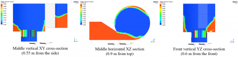
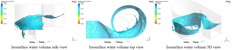
Figure 10 illustrates the water volume distribution for the 90° blade angle, supporting the findings of optimal hydrodynamic performance. The water volume pattern demonstrates a slender, focused air-core formed symmetrically at the vortex center. Unlike the 75° configuration, the free-surface boundary (the transition between fractions 0.100 and 0.900) appeared smoother and more consistent. This pattern substantiates the formation of a stable vortex with minimal power loss.
Vortex compactness is critical because a slender air-core ensures maximum fluid mass interaction with the turbine vanes. The majority of the swirling water volume remains in contact with the blades, enabling efficient energy conversion. This condition is a key determinant in achieving high energy extraction, further validating the 90° design as the optimal configuration.
Figure 10. Water volume distribution of the vortex chamber at 90° blade angle (various cross-sections)
3.2.3 The 105° blade angle configuration
Figure 11 corroborates the findings of hydrodynamic distortion at the 105° angle. The air-core area appeared expanded and exhibited a highly irregular boundary pattern. This outcome aligns with existing literature, indicating that the air-core widens at this specific angle. The free-surface boundary (the transition between fractions 0.100 and 0.900) displayed significant undulations, confirming an unstable and severely distorted vortex. The expansion of the air-core is directly attributable to premature flow separation, which diminishes the volume of water interacting with the blades. Consequently, this leads to increased hydraulic losses and reduced overall efficiency.
Figure 11. Water volume distribution of the vortex chamber at 105° blade angle (various cross-sections)
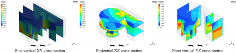
3.3 Pressure distribution
Pressure distribution analysis reveals the differential pressure gradient along the blades. Fundamentally, this gradient generates the thrust force acting upon the turbine rotor.
3.3.1 The 75° blade angle configuration
Figure 12 displays the pressure contours for the 75° blade angle, further supporting the conclusion of suboptimal efficiency. The maximum pressure reached 5,741.087 Pa, concentrated in the lower section of the intake area and immediately upstream of the blades. While this indicates initial thrust potential, the resulting pressure gradient was asymmetrical. After passing the blades, the pressure dropped to a minimum of 6.720 Pa. This asymmetrical pattern results from the unstable vortex and the widened air-core, which hinders the creation of a consistent pressure differential between the pressure and suction sides of the blades.
Figure 12. Pressure distribution of the vortex chamber at 75° blade angle (various cross-sections)
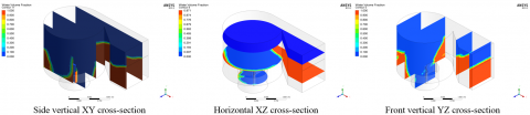
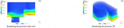
3.3.2 The 90° blade angle configuration
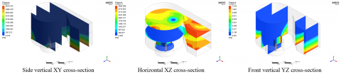
The 90° configuration exhibits the most favourable pressure distribution, as shown in Figure 13. The maximum pressure reached 5,777.397 Pa, concentrated uniformly within the intake area, ensuring that the fluid imparts maximum thrust onto the pressure side of the blades. A key feature of this configuration is the pressure gradient established following the blade interaction. The pressure dropped significantly to a minimum of 3.154 Pa on the suction side, creating a large differential pressure drop that signifies highly effective energy extraction. The pressure contours display a consistent and symmetrical pattern around the blade area, indicating a stable vortex flow.
Figure 13. Pressure distribution of the vortex chamber at 90° blade angle (various cross-sections)
3.3.3 The 105° blade angle configuration
The pressure contours for the 105° angle exhibit an unfavorable and distorted pattern (Figure 14). Although the maximum pressure reached 5,892.066 Pa, the distribution surrounding the blades demonstrated significant distortion. This irregular pressure profile results from premature flow separation, which disrupts the effective transfer of momentum. Consequently, this separation prevents the maximization of the differential pressure drop. These conditions lead to increased hydraulic losses and reduced vortex quality, collectively decreasing turbine efficiency. The suboptimal pressure distribution confirms that the 105° design is ineffective for this application.
Figure 14. Pressure distribution in the vortex chamber at 105° blade angle (various cross-sections)
Numerical results demonstrate a critical correlation between blade angle, hydrodynamic stability, and energy conversion efficiency. The 90o configuration was identified as the optimal design, providing superior performance compared to the 75° and 105° variants. Specifically, the 90° model achieved a 41.3% increase in maximum velocity (4.376 m.s⁻¹) and a 53.1% reduction in suction pressure (3.154 Pa) relative to the 75° design. These quantified improvements facilitate an enhanced pressure gradient, resulting in higher torque generation and maximized energy capture, as summarized in Table 1. Deviation from the 90° angle significantly degrades turbine performance through distinct failure mechanisms. At 75°, inefficiency stems from a lack of flow stability. Although a velocity of 3.096 m.s⁻¹ was achieved, the kinetic energy failed to consolidate into a stable vortex ring. Conversely, the performance decline at 105° was dominated by premature flow separation. Despite recording the highest peak velocity (4.657 m.s⁻¹) and pressure (5,892.066 Pa), the distorted profile and widened air-core indicate severe hydrodynamic losses. These findings suggest that high peak values do not guarantee efficiency; rather, the uniformity and symmetry of the flow field are essential for effective energy conversion [35, 36].
Table 1 synthesizes the visual observations from the velocity, water volume fraction, and pressure contours into quantitative performance indicators. Although the 105° configuration exhibits the highest peak velocity, the data demonstrate that optimal performance is governed by flow symmetry and pressure stability rather than maximum velocity alone. This comparison reinforces the conclusion that the 90° configuration offers the most balanced and effective hydrodynamic performance. Mechanically, the 90° configuration is superior due to the integrated relationship between vortex structural integrity and pressure drop [37]. The formation of a dense, stable vortex ring ensures that the water volume fraction remains focused on the blade surfaces, thereby minimizing energy dissipation from turbulence [38, 39]. This stability yields a symmetric and favorable pressure gradient, providing mechanical confirmation of efficient momentum transfer [40, 41]. Consequently, the 90° design is the most effective for practical applications as it maximizes the pressure differential required for consistent force generation [42].
Table 1. Comparative hydrodynamic performance metrics across different vane angle configurations (75°, 90°, and 105°)
|
Parameter |
Statistics |
75° Vane Angle (Suboptimal) |
90° Vane Angle (Optimal) |
105° Vane Angle (Suboptimal) |
|
Flow velocity, v (m s⁻¹) |
Maximum |
3.096 |
4.376 |
4.657 |
|
|
Minimum |
0 |
0 |
0 |
|
|
Flow-field characteristics |
Fragmented, unstable, predominantly low velocity |
Dense, symmetrical, forms a compact vortex ring |
Diffuse, unstable, flow separation occurs |
|
Pressure, P (Pa) |
Maximum |
5,741.087 |
5,777.397 |
5,892.066 |
|
|
Minimum |
6.720 |
3.154 |
— |
|
|
Pressure-field characteristics |
Asymmetrical gradient, low thrust potential |
Highly effective gradient, large and symmetrical pressure drop |
Distorted due to premature flow separation |
|
Water volume fraction |
Air nucleus |
Expanded and unfocused |
Slender and highly focused |
Very wide and irregular |
|
|
Stability |
Wavy and asymmetrical surface |
Smooth and highly consistent |
Strong undulations |
|
Efficiency |
Status |
Low |
Highest (Maximum) |
Declining (Degradation) |
3.4 Discussion
Overall, the integrated interpretation of the velocity contours (Figures 6-8), water volume fraction distributions (Figures 9-11), and pressure fields (Figures 12-14) provides a coherent explanation of the hydrodynamic mechanisms governing turbine performance. The velocity visualizations demonstrate that uniform tangential velocity and vortex compactness, most evident in the 90° configuration, are essential for maintaining effective momentum transfer from the flow to the turbine blades. This stable vortex structure directly influences air-core formation, as shown by the water volume fraction results, where a slender and symmetric air-core maximizes fluid–blade interaction while minimizing hydraulic losses. These flow characteristics are reflected in the pressure distributions, where the 90° blade angle exhibits the most symmetric pressure field and the largest differential pressure drop across the blades, indicating efficient force generation and energy extraction. Table 1 synthesizes these visual and qualitative observations into quantitative performance metrics, demonstrating that optimal turbine efficiency is governed not by peak velocity alone, but by the combined balance of vortex stability, air-core compactness, and pressure-gradient symmetry. This integrated analysis supports the conclusion that the 90° blade configuration provides the most favorable hydrodynamic conditions for maximizing energy capture in the GWVHT.
This study concludes that the blade angle configuration fundamentally dictates the energy conversion efficiency of a three-bladed GWVHT by governing vortex structural integrity. The 90° blade angle is identified as the optimal design, as it achieves the most effective balance between vortex stability, air-core compactness, and pressure-gradient symmetry. This configuration yields a superior hydrodynamic environment characterized by a stable vortex ring and a maximum velocity of 4.376 m.s-1 and a slender, focused air-core. Most significantly, it establishes a highly symmetric and consistent pressure gradient, dropping to a suction pressure of 3.154 Pa, which represents a 53.1% improvement in suction effectiveness compared to the 75° design. In contrast, deviations to 75° and 105° lead to suboptimal performance; the former suffers from rotational instability and a fragmented velocity profile, while the latter experienced severe premature flow separation despite recording the highest peak velocity of 4.657 m.s-1. These findings demonstrate that the 90° configuration maximizes the extractable differential pressure drop and momentum transfer, providing a robust framework for enhancing electricity generation viability in ultra-low-head water sources.
This study was funded by the Ministry of Research, Technology, and Education, Republic of Indonesia, and LPPM Politeknik Negeri Lhokseumawe under the Grant No. 3938/PL20/PT.01.03/2025.
[1] Frey, G.W., Linke, D.M. (2002). Hydropower as a renewable and sustainable energy resource meeting global energy challenges in a reasonable way. Energy Policy, 30(14): 1261-1265. https://doi.org/10.1016/S0301-4215(02)00086-1
[2] Permana, A.S., Potipituk, C. (2024). Harmonizing power generation and environmental conservation through micro-hydro systems. In Brightening Tomorrow Together, pp. 1-34. https://doi.org/10.1007/978-3-031-73486-1_1
[3] Akhyar, A., Sofyan, S.E. (2025). A review of vortex water turbine design for sustainable energy generation (principles, optimization, and validation). Energy Conversion and Management: X, 26: 100895. https://doi.org/10.1016/j.ecmx.2025.100895
[4] Zamzami, Z., Akhyar, A., Suriadi, S., Sofyan, S.E., Khairil, K., Hasannuddin, T., Yassir, Y. (2025). The influence of water velocity and blade number variation on the performance of water vortex turbines. Multidisciplinary Science Journal, 8(1): 2026068. https://doi.org/10.31893/multiscience.2026068
[5] Zhang, T.T., Elsakka, M., Huang, W., Wang, Z.G., Ingham, D.B., Ma, L., Pourkashanian, M. (2019). Winglet design for vertical axis wind turbines based on a design of experiment and CFD approach. Energy Conversion and Management, 195: 712-726. https://doi.org/10.1016/j.enconman.2019.05.055
[6] Almohammadi, K.M., Ingham, D.B., Ma, L., Pourkashan, M. (2013). Computational fluid dynamics (CFD) mesh independency techniques for a straight blade vertical axis wind turbine. Energy, 58: 483-493. https://doi.org/10.1016/j.energy.2013.06.012
[7] Wang, X., Du, P., Yao, L., Zou, Z., Zeng, F. (2023). Uncertainty analysis of measured geometric variations in turbine blades and impact on aerodynamic performance. Chinese Journal of Aeronautics, 36(6): 140-160. https://doi.org/10.1016/j.cja.2023.03.041
[8] Frant, M., Kozakiewicz, A., Kachel, S. (2020). Analysis of impact of gust angle and velocity on the position of stagnation point. Advances in Science and Technology Research Journal, 14(4): 49-57. https://doi.org/10.12913/22998624/123006
[9] Li, B., Zhou, D.L., Wang, Y., Shuai, Y., Liu, Q.Z., Cai, W.H. (2020). The design of a small lab-scale wind turbine model with high performance similarity to its utility-scale prototype. Renewable Energy, 149: 435-444. https://doi.org/10.1016/j.renene.2019.12.060
[10] Li, H., Steurer, M., Shi, K.L., Woodruff, S., Zhang, D. (2006). Development of a unified design, test, and research platform for wind energy systems based on hardware-in-the-loop real-time simulation. IEEE Transactions on Industrial Electronics, 53(4): 1144-1151. https://doi.org/10.1109/TIE.2006.878319
[11] Barlas, T.K., van Kuik, G.A. (2010). Review of state of the art in smart rotor control research for wind turbines. Progress in Aerospace Sciences, 46(1): 1-27. https://doi.org/10.1016/j.paerosci.2009.08.002
[12] Shamsuddeen, M.M., Ma, S.B., Park, N.H., Kim, K.M., Kim, J.H. (2023). Design analysis and optimization of a hydraulic gate turbine for power production from ultra-low head sites. Energy, 275: 127371. https://doi.org/10.1016/j.energy.2023.127371
[13] Maisuria, M., Ratadiya, L., Patel, A. (2024). Computational investigation and optimization of the bulb turbine for ultra-low head application. Renewable Energy, 230: 120876. https://doi.org/10.1016/j.renene.2024.120876
[14] Pędzisz, I., Magryta, P., Pietrykowski, K. (2024). Computational fluid dynamics studies of a vertical axis wind turbine with a variable swept area. Advances in Science and Technology Research Journal, 18(2): 185255. https://doi.org/10.12913/22998624/185255
[15] Kabat, S.R., Panigrahi, C.K., Ganthia, B.P., Barik, S.K., Nayak, B. (2022). Implementation and analysis of mathematical modeled drive train system in type III wind turbines using computational fluid dynamics. Advances in Science and Technology Research Journal, 16(1): 180-189. https://doi.org/10.12913/22998624/144753
[16] Wu, J., Jin, Y., Hao, Y., Lu, J. (2021). Identification of the control factors affecting water quality variation at multi-spatial scales in a headwater watershed. Environmental Science and Pollution Research, 28(9): 11129-11141. https://doi.org/10.1007/s11356-020-11352-4
[17] Ibrahim, A.A., Elbaz, A.M., Melani, P.F., Mohamed, O.S., Bianchini, A. (2022). Power augmentation of Darrieus wind turbine blades using trapped vortex cavity. Journal of Wind Engineering and Industrial Aerodynamics, 223: 104949. https://doi.org/10.1016/j.jweia.2022.104949
[18] Maika, N., Lin, W., Khatamifar, M. (2023). A review of gravitational water vortex hydro turbine systems for hydropower generation. Energies, 16(14): 5394. https://doi.org/10.3390/en16145394
[19] Vinayakumar, B., Antony, R., Binson, V.A., Youhan, S. (2024). Experimental and numerical study on gravitational water vortex power plant for small water bodies. e-Prime - Advances in Electrical Engineering, Electronics and Energy, 7: 100460. https://doi.org/10.1016/j.prime.2024.100460
[20] Mulligan, S. (2015). Experimental and numerical analysis of three-dimensional free-surface turbulent vortex flows with strong circulation. PhD Thesis. Institute of Technology Sligo, Ireland.
[21] Kueh, T.C., Beh, S.L., Ooi, Y.S., Rilling, D.G. (2017). Experimental study to the influences of rotational speed and blade shape on water vortex turbine performance. Journal of Physics: Conference Series, 822(1): 012066. https://doi.org/10.1088/1742-6596/822/1/012066
[22] Gorle, J.M.R., Chatellier, L., Pons, F., Ba, M. (2019). Modulated circulation control around the blades of a vertical axis hydrokinetic turbine for flow control and improved performance. Renewable and Sustainable Energy Reviews, 105: 363-377. https://doi.org/10.1016/j.rser.2019.02.007
[23] Hoerner, S., Abbaszadeh, S., Maître, T., Cleynen, O., Thevenin, D. (2019). Characteristics of the fluid–structure interaction within Darrieus water turbines with highly flexible blades. Journal of Fluids and Structures, 88: 13-30. https://doi.org/10.1016/j.jfluidstructs.2019.04.011
[24] Ma, S., Jun, H., Wang, X., Ji, J. (2022). Effect of non-uniformity of rotor stagger angle on the stability of a low-speed axial compressor. Energies, 15(8): 2714. https://doi.org/10.3390/en15082714
[25] Umar, M., Baig, X.H., Wang, Z. (2024). Experimental flow performance investigation of Francis turbines from model to prototype. Applied Sciences, 14(17): 7461. https://doi.org/10.3390/app14177461
[26] Saini, G., Saini, R.P. (2019). A review on technology, configurations, and performance of cross-flow hydrokinetic turbines. International Journal of Energy Research, 43(13): 6639-6679. https://doi.org/10.1002/er.4625
[27] Mulligan, S., Casserly, J., Sherlock, R. (2016). Experimental and numerical modelling of free-surface turbulent flows in full air-core water vortices. In Advances in Hydroinformatics, pp. 549-569. https://doi.org/10.1007/978-981-287-615-7_37
[28] Zheng, G., Gu, Z., Xu, W., Lu, B., Li, Q., Tan, Y., Wang, C., Li, L. (2022). Gravitational surface vortex formation and suppression control: A review from hydrodynamic characteristics. Processes, 11(1): 42. https://doi.org/10.3390/pr11010042
[29] Velásquez, L., Rubio-Clemente, A., Chica, E. (2024). Numerical and experimental analysis of vortex profiles in gravitational water vortex hydraulic turbines. Energies, 17(14): 3543. https://doi.org/10.3390/en17143543
[30] Kan, K., Xu, Y., Li, Z., Xu, H., Chen, H., Zi, D., Gao, Q., Shen, L. (2023). Numerical study of instability mechanism in the air-core vortex formation process. Engineering Applications of Computational Fluid Mechanics, 17(1): 2156926. https://doi.org/10.1080/19942060.2022.2156926
[31] Shabara, H.M., Yaakob, O.B., Ahmed, Y.M., Elbatran, A.H. (2015). CFD simulation of water gravitation vortex pool flow for mini hydropower plants. Jurnal Teknologi (Sciences & Engineering), 74(5): 77-81. https://doi.org/10.11113/jt.v74.4645
[32] Timilsina, A.B., Mulligan, S., Bajracharya, T.R. (2018). Water vortex hydropower technology: A state-of-the-art review of developmental trends. Clean Technologies and Environmental Policy, 20(8): 1737-1760. https://doi.org/10.1007/s10098-018-1589-0
[33] Al-Obaidi, A.R., Alhamid, J., Khalaf, H. (2024). Unsteady behaviour and plane blade angle configurations' effects on pressure fluctuations and internal flow analysis in axial flow pumps. Alexandria Engineering Journal, 99: 83-107. https://doi.org/10.1016/j.aej.2024.04.048
[34] Sonawat, A., Kim, S.J., Yang, H.M., Choi, Y.S., Kim, K.M., Lee, Y.K., Kim, J.H. (2020). Positive displacement turbine – A novel solution to the pressure differential control valve failure problem and energy utilization. Energy, 190: 116400. https://doi.org/10.1016/j.energy.2019.116400
[35] Firoozi, A.A., Hejazi, F., Firoozi, A.A. (2024). Advancing wind energy efficiency: A systematic review of aerodynamic optimization in wind turbine blade design. Energies, 17(12): 2919. https://doi.org/10.3390/en17122919
[36] Masoodi, F.A., Goyal, R. (2021). Efficacy of ancillary fluid injection technique for mitigation of vortex rope in hydraulic turbines: A review. Materials Today: Proceedings, 47: 3043-3053. https://doi.org/10.1016/j.matpr.2021.05.618
[37] Seng, W.K., Tanjong, S.J. (2025). Investigation on blade angles effect on micro-gravitational water vortex system via simulation and experimental analysis. Pena Journal of Flow Dynamics, 1(1): 13-27. https://doi.org/10.37934/pjfd.1.1.1327
[38] Edirisinghe, D.S., Yang, H.S., Gunawardane, S.D.G.S.P., Lee, Y.H. (2022). Enhancing the performance of gravitational water vortex turbine by flow simulation analysis. Renewable Energy, 194: 163-180. https://doi.org/10.1016/j.renene.2022.05.053
[39] Sukadana, I.G.K., Suarda, M., Widiarta, I.P., Danus, I. (2024). CFD (Computational Fluid Dynamics) simulation of hydrodynamic vortex turbine performance: Influence of notch angle variation on flow patterns and efficiency. Natural Sciences Engineering and Technology Journal, 4(2): 336-351. https://doi.org/10.37275/nasetjournal.v4i2.56
[40] Hou, X., Yuan, J., Fu, Y., Wang, P., Zhang, P., He, N. (2024). Submerged vortex morphology and pressure fluctuation characteristics in intake sump. Journal of Applied Fluid Mechanics, 17(10): 2100-2114. https://doi.org/10.47176/jafm.17.10.2640
[41] Ullah, R., Cheema, T.A., Saleem, A.S., Ahmad, S.M., Chattha, J.A., Park, C.W. (2019). Performance analysis of multi-stage gravitational water vortex turbine. Energy Conversion and Management, 198: 111788. https://doi.org/10.1016/j.enconman.2019.111788
[42] Laín, S., López, O., Quintero, B., Meneses, D. (2013). Design optimization of a vertical axis water turbine with CFD. In Alternative Energies. Advanced Structured Materials. https://doi.org/10.1007/978-3-642-40680-5_6