Khoi Nguyen Nguyen*![]() | Lam Kim Thanh Vo
| Lam Kim Thanh Vo![]() | Thanh Duy Nguyen
| Thanh Duy Nguyen![]()
© 2025 The authors. This article is published by IIETA and is licensed under the CC BY 4.0 license (http://creativecommons.org/licenses/by/4.0/).
OPEN ACCESS
This study investigates the improvement of the aerodynamic performance of the Audi TT by implementing the Selig 1223 wing configuration as a rear spoiler. The study examines the optimization of the drag and lift coefficients by adjusting the angle of attack of the spoiler to improve vehicle stability during high-speed operation. The 3D vehicle model and spoiler were designed using SolidWorks at a 1:1 scale and conducted using Ansys Fluent computational fluid dynamics (CFD). The study analyzed the pressure and velocity distribution around the base model and the configurations with the spoiler deflection angles of 5°, 10° and 15° at an airflow velocity of 30 m/s. The results demonstrate that the 5° spoiler increases the drag coefficient by 0.07% and reduces the lift coefficient by 6.2%. The 10° configuration shows an increase in drag by 0.14% and a significant reduction in lift by 16.9%. The 15° wing achieved a maximum lift reduction of 20.3% and a substantial drag increase of 4.43%. In conclusion, the study found that a 10° deflection angle provides the optimal aerodynamic efficiency, offering the best balance between drag penalty and lift reduction benefits. This configuration delivers superior performance to enhance vehicle stability during high-speed cornering.
aerodynamic, RANS turbulence model, simulation CFD, drag coefficient, lift coefficient, S1223
In recent years, the role of fuel has garnered increasing attention as its price continues to rise following global events. Specifically, in our country, the fuel issue has not been completely resolved. Vehicular transportation in general, and automobiles in particular, remain a concern regarding the use of fossil fuels [1]. In the automotive industry, aerodynamics plays a crucial role, directly influencing vehicle movement, significantly impacting operational efficiency, stability, and fuel economy [2]. A major issue arises when cars begin to travel at high speeds, as air resistance is proportional to the square of the velocity [3]. This hinders the vehicle, leading to fuel consumption and loss of stability. Factors such as the drag coefficient Cd and lift coefficient Cl directly affect the vehicle's ability to move [3]. However, this can be mitigated by installing a rear spoiler, an accessory that increases grip between the wheels and the road surface, making the car more stable when driving at high speeds and when cornering.
Previous research [4] has shown that spoilers affect the pressure distribution behind the vehicle and the movement of airflow, thereby impacting drag and lift. Research [5] has sought to optimize the performance of the spoiler by changing the tilt angle, with many studies exploring the effect of the S1223 spoiler tilt angle on aerodynamic performance using the computational fluid dynamics (CFD) method. Study [6] contributed to a better understanding of the aerodynamic characteristics around both a simplified car model and a general Formula 1 race car model. Study [7] all indicate the significant influence of spoilers on vehicle operation. Additionally, CFD studies have provided maps of pressure and velocity distributions, where the quality of the calculated grid plays an important role in obtaining sufficiently detailed maps.
However, several research gaps still need to be addressed. First, there is still a lack of detailed and comprehensive studies on the specific spoiler angle range and investigating its effect on different vehicle models [8]. Current studies have only tested the angle of inclination within limited ranges for example, from 0 ÷ 15° or from 0 ÷ 20° with a jump of 5° [8]. Second, research often uses basic vehicle models such as sedans, high-performance vehicles or simplified models such as Ahmed [9]. Particularly, although study indicate that the Audi TT had to be equipped with a rear spoiler to overcome the problem of cornering instability, there was a lack of in-depth aerodynamic studies, especially CFD studies, which focused directly on the Audi TT model to optimize the spoiler. Third, optimization usually focuses on a specific factor [10], while the big challenge is to design a model that achieves the appropriate lift and resistance coefficient values. This requires a complex goal optimization problem, balancing the reduction of lift and drag, which studies have not been able to completely solve for each specific car model [11]. Finally, although CFD studies provide maps of pressure and velocity distributions, the level of detail and the ability to analyze complex flow structures is still limited [12]. The lack of detailed studies of the flow field along the body of the vehicle loses the ability to recognize the flow of the bodywork, its shape and density. Studies have also shown that low grid density can lead to inaccurate calculation and prediction of near-vehicle flows, especially in complex areas [13].
To address the above research gaps, this study focuses on using a spoiler designed based on the Selig 1223 Aerofoil [4, 5], a proven design, and investigates different deflection angles between the direction of the wind acting on the wing and the horizontal axis at angles of 5°, 10°, and 15°. This study will comprehensively investigate the effects of the S1223 spoiler at different tilt angles: No spoiler (case 1) and with spoiler at angles of 5°, 10°, 15° (equivalent to case 2, 3 and 4). This angular band covers a standard range commonly used in wing aerodynamic studies (0 ÷ 15°) and allows the observation of changes in lift and drag [13]. The specific objective is to analyze the effect of the S1223 rear spoiler angle on aerodynamics on the 2019 Audi TT, to determine the optimum spoiler angle for aerodynamic performance and to provide an understanding of the behavior of the flow acting on the vehicle surface (formation of edges and tangled flow).
The novelty of this study focuses on the Audi TT car model, which has been historically noted for the need for spoilers to improve stability. By simulating the combination of the S1223 [5-7] spoiler with the Audi TT model, this study will address aspects related to aerodynamic optimization for a specific model and solve the problem of optimizing the balance between drag coefficient and aerodynamic characteristic lift coefficient [14]. The research method uses CFD simulation [15] based on the Fluent function of Ansys software, performed on both the original model and the improved model at different spoiler angles. The detailed 3D model of the 2019 Audi TT with the S1223 spoiler is designed using SolidWorks software combined with the computational fluid dynamics simulation method [15]. The results of the simulation will provide a basis for comparing pressure, velocity, and various other metrics of the model before and after the addition of the spoiler, not only clarifying the angles that affect aerodynamic characteristics but also analyzing in detail the pressure distribution on the vehicle body and the velocity distribution on the model.
2.1 Building a 3D model of the Audi TT
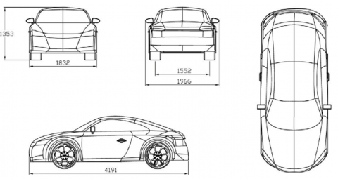
For this paper, the researcher sketched a 3D model of the 2019 Audi TT with the following dimensions: length L = 4191 mm, height H = 1353 mm, width W = 1832 mm on the coordinate axes of the software, which is described in Figure 1.
Figure 1. 3D model of Audi TT
The model was designed to be simplified, omitting details, and the chassis was flattened to achieve time efficiency during simulation.
2.2 Building a 3D model of the rear spoiler
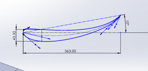
The rear spoiler was constructed according to the specifications of James Selig. Basically, this is a reverse wing compared to an aircraft wing [4, 5]. Because aircraft need to improve lift for takeoff, while cars need to reduce lift to increase grip between the wheels and the road surface. Figure 2(a) shows the shape of the rear spoiler, while Figure 2(b) shows the completed spoiler [6, 7]. The design parameters are described: Selig 1223 Aerofoil, wing length S = 1.240 m, length from tip to tail C = 0.363 m, thickness 12% C, rounded arc is 0.75% C [6], deflection angle relative to the wind direction from 5° to 15°, with an increment of 5° [7], and distance from the wheel center h = 0.8 m.
(a) Sketch of spoiler according to S1223 model
(b) Rear spoiler
Figure 2. Rear spoiler model
2.3 Computational domain
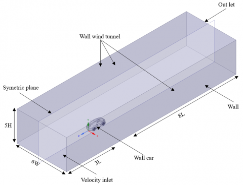
The computational domain is like a rectangular box with specific dimensions depending on the simulation conditions and is understood as the space surrounding the sample. The computational domain is usually larger than the sample so that the airflow is not affected by the model when conducting research. This size has been studied and found to be a suitable computational domain for use in aerodynamic [15] simulation through Figure 3 according to the dimensions 5H (height), 6W (width), 3L, 8L (length).
Figure 3. Size of the computational domain
3.1 Governing equations
When studying the motion of fluid flow, especially fluid dynamics, it is often described by the Navier-Stokes equations [9, 10]. In addition, when studying aerodynamics on automobiles, it has been hypothesized that the gas is incompressible, so the above equation is based on two laws: the continuity equation and the momentum conservation equation.
Continuity Equation:
$\frac{\partial u}{\partial x}+\frac{\partial v}{\partial y}+\frac{\partial w}{\partial z}=0$ (1)
Momentum Conservation Equation:
${{\partial }_{i}}{{u}_{i}}+{{u}_{j}}{{\partial }_{j}}{{u}_{i}}=-\frac{1}{\rho }{{\partial }_{i}}p+v{{\partial }_{j}}{{\partial }_{j}}{{u}_{i}}$ (2)
For the simulation above, the researcher used the RANS (Reynolds-averaged Navier-Stokes) turbulence model to simplify the problem:
${{\partial }_{i}}\overline{{{u}_{i}}}=0$ (3)
${{\partial }_{t}}\overline{{{u}_{i}}}+\overline{{{u}_{j}}}{{\partial}_{j}}\overline{{{u}_{i}}}=-\frac{1}{\rho }{{\partial}_{i}}\overline{p}+\frac{1}{\rho}{{\partial }_{j}}\left( {{\tau }_{ij}}-\rho \overline{u{{'}_{i}}u{{'}_{i}}} \right)$ (4)
where, $u, v, w$ - velocity of the fluid element on the $x, y, z$ coordinate axes; $\partial_i u_t$ - partial derivative of $u$ with respect to time; $p$ - air pressure (Pa); $u_i$ component of the gas velocity vector; $v$ - kinematic viscosity of air $(\mathrm{kg}.\mathrm{m}/\mathrm{s}^{-1})$; $\rho \overline{u_i^{\prime} u_i^{\prime}}$ - Reynolds stress; $\tau_{i j}$ - Stress Tensor [9].
In addition, the researcher used the k - ε turbulence model, by combining two equations describing the turbulent kinetic energy k and the equation describing the dissipation of the turbulent coefficient ε. CFD simulation using the standard k - ε model with Standard Wall Function [16]. With this model, the equation can handle and predict the dispersion of laminar or turbulent flow in aerodynamic problems [17].
In the study of aerodynamic characteristics of sports cars equipped with rear spoilers, the airflow velocity was set at 30 m/s [8].
Other studies have also used velocities in this range or higher for vehicle simulations: A study on the effect of gurney flaps on the rear spoiler of formula cars using velocities of 25, 50 and 88.89 m/s [8-10]. A comparative study of the flow characteristics of the BMW M6 and Audi R8 was conducted at velocities of 27.7, 41.6 and 55.56 m/s [14]. These figures show that 30 m/s is a standard speed and is relevant to actual driving conditions, especially on highways or in situations that require high aerodynamic performance.
Table 1. Boundary conditions and solver methodology
|
Boundary Conditions |
|
|
Model |
k-ε |
|
Material |
Air |
|
Inlet |
30 m/s |
|
Outlet |
0 Pa |
|
Symmetric plane |
No slip |
|
Wall wind tunnel |
|
|
Wall |
|
|
Wall car |
|
|
Solver Methodology |
|
|
Coupled |
|
|
Second order upwind |
|
|
Standard initialization |
|
|
Z velocity: - 30 m/s |
|
|
Number of iterations: 200 |
|
${{\operatorname{R}}_{e}}=\frac{\rho .v.L}{\mu }=\frac{1,204.30.4,191}{1,{{81.10}^{-5}}}=8,{{363.10}^{-6}}$ (5)
In Eq. (1) car studies, the realizable k-ε model was chosen for its highest accuracy compared to other models such as SST k-ω and Spalart-Allmaras for established reference Cd data [8, 9].
Although the standard k-ε model may not be the most accurate for complex flow fields with adverse pressure gradients, flow curvature, or jet flow, the Realizable k-ε version has been widely used in automotive aerodynamics applications with positive results [16, 17].
For simple car models such as the Ahmed body, the Realizable k-ε model has shown results consistent with experimental data with low error [18].
The k-ε model, including the realizable version, is known for its "good convergence speed and relatively low memory requirements", making it a practical choice for industrial applications. With the main objective of obtaining overall aerodynamic coefficients such as drag coefficient Cd and lift coefficient Cl with reasonable accuracy, the Realizable k-ε model can meet the set requirements with acceptable error in predicting these coefficient values [16-18].
3.2 Mesh generation and boundary conditions
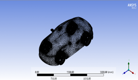
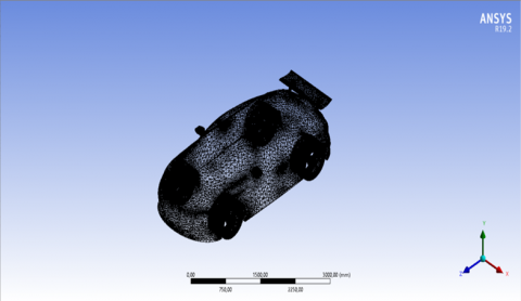
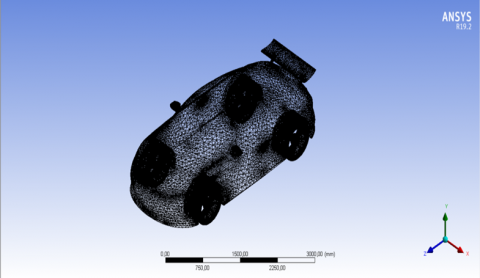
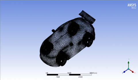
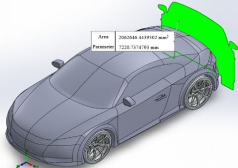
Mesh generation (meshing) is considered an action to discretize the computational area to simulate small elements with simple shapes to perform approximate calculations when using CFD simulation [9]. Meshing has a significant impact on the simulation results because it relates to the number of elements and the simulation time [10]. For this study, the Audi TT model with the rear spoiler was created based on the software's calculations meshing and is shown in Figure 4. The simulation was used a velocity of 108 km/h (30 m/s), a pressure of 0 Pa and air as the working fluid (ρ = 1.204 kg/m³). The main parameters are listed in Table 1. The frontal area was calculated accurately on SolidWorks software, and this area remained unchanged after the improvement, A = 2.06 m2.
A systematic mesh independence study was conducted to ensure solution accuracy while optimizing computational efficiency [16]. The simulation cases were meshed using unstructured tetrahedral elements [17]. As a result, case 1 contained approximately 333,880 nodes and 1,696,808 elements, case 2 contained 355,078 nodes and 1,810,388 elements, case 3 contained 353,452 nodes and 1,801,194 elements, and finally case 4 contained 354,790 nodes and 1,809,407 elements. Details of the grid are presented in Table 2.
(a)
(b)
(c)
(d)
*Note: (a) No spoiler, (b) spoiler at 5° angle, (c) spoiler at 10° angle, and (d) spoiler at 15° angle. This note applies to the entire study, corresponding to cases 1, 2, 3, and 4.
Figure 4. Unstructured tetrahedral mesh generation for the model
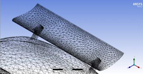
Figure 5. Mesh around spoiler use unstructured tetrahedral
Table 2. Information about mesh cases
|
Cases |
1 |
2 |
3 |
4 |
|
Element Order |
Quadratic |
|||
|
Nodes |
333880 |
355078 |
353452 |
354790 |
|
Elements |
1696808 |
1810388 |
1801194 |
1809407 |
|
Growth Rate |
1.2 (20%) |
|||
|
Min size |
15.223 mm |
16.56 mm |
14.82 mm |
13.951 mm |
|
Max size |
600 mm |
|||
|
Average Surface Area |
1.0395e+006 mm2 |
1,021e+ 006 mm2 |
1.0232e+006 mm2 |
1.0381e+006 mm2 |
Figure 6. Frontal area of the Audi TT
When designing the car and spoiler (Figure 5), authors calculated so that the frontal area before and after the improvement remained unchanged. The purpose is to keep the drag coefficient Cd unchanged when using the method of projecting light onto the car to obtain the shadow. The area obtained is the drag area of the car. The results are presented in Figure 6.
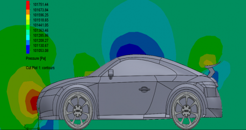
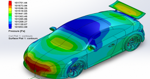
4.1 Pressure distribution around the model
Simulating the pressure distribution of the airflow resulted in the images below.
Exterior shape is a prerequisite for improving vehicle aerodynamics [10, 11]. Cars are designed to optimize aerodynamic performance, reducing drag and improving fuel consumption [2].
The rear shape is particularly important, as large rear sections create vortices and pressure differences that increase drag. Other optimization methods include reducing ground clearance and proper air intake arrangement [2].
(a)
(b)
(c)
(d)
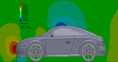
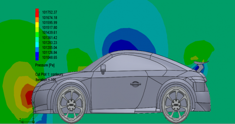
Figure 7. Pressure distribution of airflow at the right plane of the model
Figure 7 makes it easy for us to see that the pressure distributed on the front of the car, the hood, and the windshield does not have much difference. The column on the left shows the value when simulating, with blue representing low pressure and red representing high pressure [9-11]. From this, we can analyze the model, when adding a spoiler, the pressure distributed on the roof of the car has decreased compared to the original model. The blue area has increased significantly. This is due to the airflow affecting the model, causing it to separate and create separation points and vortices around the model.
(a)
(b)
(c)
(d)
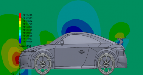
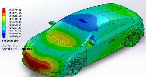
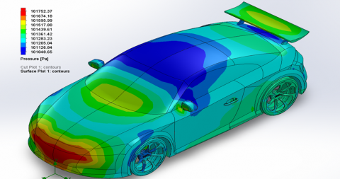
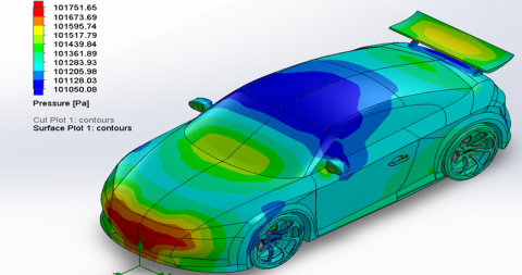
Figure 8. Pressure distribution on the original and improved models (5°, 10°, 15° angles)
Table 3. Comparison of velocity and pressure results behind the car
|
Case\Parameter |
Pressure |
Velocity |
||
|
Max |
Min |
Max |
Min |
|
|
1 |
101752.34 |
100935.64 |
35.499 |
0 |
|
2 |
101752.37 |
101048.65 |
35.108 |
0 |
|
3 |
101751.65 |
101050.08 |
35.132 |
0 |
|
4 |
101751.44 |
101053.08 |
35.125 |
0 |
As the spoiler angle gradually increases to create lift, the spoiler may occupy a certain amount of frontal bumper area of the vehicle or increase the frictional resistance of the spoiler shape [12, 13].
In Figure 8, at the front of the model, the airflow has a higher pressure because the airflow velocity tends to decrease at the front of the car. This can be explained through Bernoulli’s principle that: pressure is inversely proportional to velocity, and where there is high pressure, the velocity will decrease [9-11]. Specifically, the pressure value at the right plane is described in Table 3.
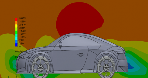
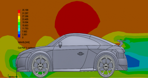
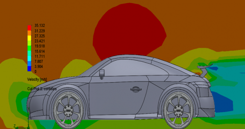
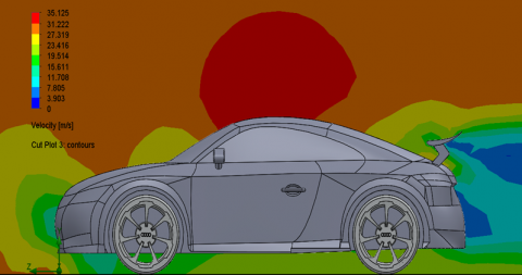
4.2 Velocity distribution around the model
Simulating the velocity of the airflow resulted in the images below.
Based on the Bernoulli principle and the pressure difference between the upper and lower surfaces of the spoiler when mounted upside down on the Audi TT model [9-11].
(a)
(b)
(c)
(d)
Figure 9. Velocity distribution of airflow on the right plane of the car
As the airflow passes through the wings on the lower surface, there is less pressure and higher pressure on the upper surface, thereby reducing the lifting force to create grip between the wheel and the pavement [4-6]. Pressure is inversely proportional to velocity and where there is high pressure, the velocity will be low.
The relationship between the two quantities characterizes generally nonlinear aerodynamics, where Cd increases faster than Cl at large angles [7, 8].
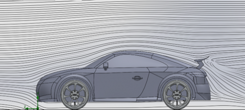
Figure 9 illustrates the velocity distribution around the Audi TT at the right plane. The airflow is obstructed at the front, splitting at a separation point into two streams: one over the model and one under the carriage [9-11]. The left column indicates simulation values, with blue for 0 m/s and red for high velocity. Brown highlights airflow impacting areas of abrupt shape change, where velocity above the model increases significantly.
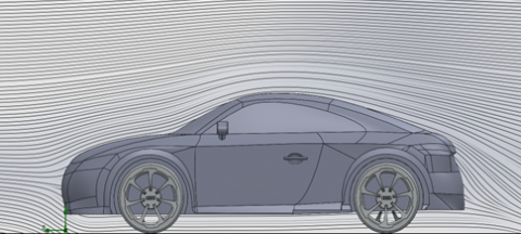
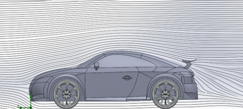
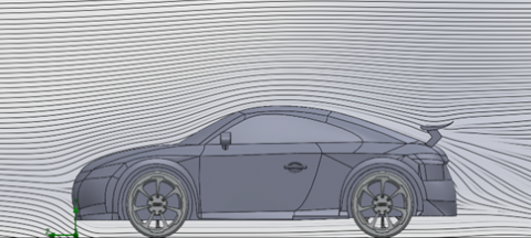
At the same time, the drag coefficient increases when early separation occurs, the vortex area begins to appear a lot at the rear of the car [17-19]. This area usually has lower pressure than the front of the car, and the larger the difference, the greater the drag coefficient. Observe Figure 10 to see the vortex behind the vehicle body, in Figure 10(a) this vortex area is relatively large and dense, it is close to the tail of the car. The remaining, Figures 10(b-d) when the spoiler is attached, the vortex area here has decreased, the lines are thinner and sparser, moving further behind the tail of the car.
(a)
(b)
(c)
(d)
Figure 10. Airflow affecting the surface of the Audi TT
Case 1 - No spoiler: The flow exhibits basic aerodynamic characteristics with smooth flow lines guided upward around the vehicle body. At the rear, flow separation creates a moderate recirculation zone with slight curvature, resulting in stable Cd but no lift reduction.
Case 2 - 5° spoiler: Spoiler addition significantly alters rear flow structure. Airflow over the upper surface creates a low-pressure zone underneath and high-pressure zone above, generating downward flow and pressure [17]. However, this increases drag coefficient due to additional resistance.
Case 3 - 10° spoiler: The 10° angle achieves optimal aerodynamic balance. Flow maintains surface adhesion without premature separation, creating effective pressure differentials between upper and lower surfaces [17]. The rear turbulent zone is well-controlled with minimal vortices, and flow lines converge stably, minimizing energy loss.
Case 4 - 15° spoiler: Excessive angle causes early flow separation on the spoiler's upper surface. Large unstable vortex zones appear behind the spoiler, creating complex multi-layered vortices of varying sizes and intensities. Although lift reduction continues, efficiency decreases significantly due to critical angle effects, resulting in substantial drag coefficient increase.
With the results collected from Table 3, we can compare that the velocity value before and after equipping the spoiler decreases almost linearly at angles of 10° and 15°. From Figure 8 and Figure 9, it is easy to recognize that: when adding a spoiler, the velocity behind the tail area of the car has decreased. Specifically: in case 2, the velocity has decreased by 15.23%; in case 3, it has decreased by 23.30% compared to case 1, the pressure here has also increased significantly.
4.3 Aerodynamic forces on the 3D Audi TT model
Drag is the force opposite to lift and is a component of fluid dynamics parallel to the direction of flow [9-11]. The results of the Audi TT model simulation have determined the Cd and Cl values described in Table 5. From the above values, the forces are calculated through the formula below.
Air Drag Force:
${{F}_{d}}=\frac{1}{2}{{C}_{d}}\rho A{{U}^{2}}$ (6)
Lift Force:
${{F}_{l}}=\frac{1}{2}{{C}_{l}}\rho A{{U}^{2}}$ (7)
in which, Fd,l – corresponding to drag and lift force (N); Cd,l - air drag coefficient and lift coefficient; U - velocity of the airflow during simulation (m/s); A - frontal area of the car (m2), r - air density (kg/m3) [9-11].
4.4 Aerodynamic calculation results
After running the simulation on the software, the results are as shown in the following Tables 4 and 5.
Besides, three different levels of grid smoothness to ensure the independence of the CFD simulation results [16, 17]. The results show that the Cd resistance coefficient and the Cl lift coefficient decrease as the mesh is smoother, with the Fine mesh giving the lowest value and highest accuracy [18].
Mesh convergence study is an important part of the validation of the numerical model by comparing CFD results with experimental data.
The difference between medium and fine averages 1.42% Cd and 2.24% Cl, which is within the acceptable range of < 5%. Coarse has a difference of 3-4% compared to fine mesh and not suitable for simulation.
Table 4. Comparison of results for coarse, medium, and fine meshes
|
Case |
Mesh Refinement |
Cd |
Cl |
|
1 |
Coarse |
0.4432 |
0.4125 |
|
Medium |
0.4335 |
0.4086 |
|
|
Fine |
0.4265 |
0.3969 |
|
|
2 |
Coarse |
0.4436 |
0.3938 |
|
Medium |
0.4326 |
0.3865 |
|
|
Fine |
0.4268 |
0.3797 |
|
|
3 |
Coarse |
0.4420 |
0.3422 |
|
Medium |
0.4332 |
0.3383 |
|
|
Fine |
0.4271 |
0.3297 |
|
|
4 |
Coarse |
0.4615 |
0.3259 |
|
Medium |
0.4509 |
0.3214 |
|
|
Fine |
0.4454 |
0.3163 |
Research shows that the preprocessing stage of analytical CFD, including network generation tasks, has an impact on the reliability of the obtained results [17]. The quality and the password of the imaging system significantly affect the accuracy and stability of the calculation [19].
A well-converged network will provide more accurate results, closer to the actual or theoretical results. It helps to confirm that the numerical model is capable of accurately predicting the aerodynamic properties of the object [20].
Table 5. Table comparing Cd and Cl coefficient results when simulating
|
Parameter/Model |
Original Model |
Model with Spoiler |
||
|
5° |
10° |
15° |
||
|
Drag Coefficient (Cd) |
0.4265 |
0.4268 |
0.4271 |
0.4454 |
|
Drag Force Fd(N) |
476.030 |
476.441 |
476.757 |
497.144 |
|
Lift Coefficient (Cl) |
0.3969 |
0.3723 |
0.3297 |
0.3163 |
|
Lift Force Fl (N) |
443.065 |
415.831 |
368.07 |
353.035 |
The aerodynamic performance evaluation reveals critical insights into the trade-off between drag and lift coefficients across different spoiler configurations.
From Table 5 results, the original model exhibits a Cd of 0.4265. The systematic analysis of various deflection angles demonstrates distinct performance characteristics that require careful consideration for optimal vehicle dynamics.
At a 5° deflection angle, the spoiler configuration shows minimal impact on drag with Cd increasing marginally to 0.4268 (only 0.07% increase), while achieving a notable 6.2% reduction in Cl. This configuration demonstrates that even small angular adjustments can provide meaningful aerodynamic benefits with negligible drag penalty [20].
The 10° deflection angle represents the optimal balance point in this analysis. While the drag coefficient increases moderately by 0.23% compared to the original model, the lift coefficient experiences a substantial 10.8% reduction. Specifically, the lift force decreases from 443.065N to 368.07 N (a reduction of 75 N), while drag increases minimally from 476.030 N to 476,757 N (an increase of only 0.727 N). This configuration achieves the highest aerodynamic efficiency by providing significant downforce enhancement with acceptable drag penalty [21, 22].
At the 15° deflection angle, performance efficiency deteriorates significantly. The drag coefficient increases substantially by 4.7%, while the lift coefficient decreases by 20.20% compared to the original model. Although this configuration provides the maximum downforce reduction from 443.065 N to 353.035 N, the dramatic increase in drag coefficient indicates strong flow separation, as evidenced in Figure 9(d), making this configuration aerodynamically inefficient.
Such as, reduction of the lift coefficient and the increase drag coefficient at an angle of 10° are traded off with an acceptable Cd increase of 0.14% compared to the original model. Therefore, the case with the 10° angle spoiler is the most optimal for the S1223 model on the Audi TT, providing optimal efficiency between lift and drag.
Furthermore, when experimenting in the wind tunnel, as well as verifying the accuracy of the CFD simulation method. Particularly excellent, the research of Phuc et al. [10] on the aerodynamic properties of the simple Ahmed model has achieved impressive accuracy with an error of only 2.35% between the CFD value (0.291) and the experiment (0.298) for the resistance coefficient Cd [10]. This is considered a successful simulation study when the deviation from reality is very low. In the study of formula racing, Phuc et al. [10] validated the CFD results with an error of 7.85% compared to the reference data, using the Realizable k-ε perturbation model with 1,745,573 grid cells [7].
Kurec's [13] study on improving the aerodynamics of Arrinera Hussarya sports vehicles shows that the absolute percentage error of the drag coefficient (Cd) is 3.8% and the absolute percentage error of the lift factor (Cl) is 6.5% when validating the numerical model using test data from the MIRA wind tunnel.
Research by Renold Elsen et al. [14] on BMW M6 and Audi R8 sports cars shows a very good match between CFD and experimental results. For the BMW M6, the error ranges from 1.46% at low speed (27.77 m/s) to 7.03% at medium speed (41.6 m/s), then drops to 4.99% at high speed (55.56 m/s). Notably, the Audi R8 exhibits excellent accuracy with an extremely low error of only 0.36% to 0.72% at all test speeds. Through this study, the gap between CFD simulation and experiment is narrowing, confirming that CFD simulation is completely reliable [14].
In conclusion, vehicle aerodynamics studies have quantified the error between CFD and experiment at less than 8%, with many cases achieving an error of less than 5% and even less than 1%, reinforcing the role of CFD as a reliable design and optimization tool in the field of vehicle aerodynamics.
This paper studies the influence of rear spoiler deflection angle on the aerodynamic characteristics of the 2019 Audi TT model using RANS with the Realizable k-ε turbulence model in CFD simulation [14-16]. The method accurately predicts airflow, pressure, and velocity patterns with high accuracy and low implementation cost. Beyond automotive applications, CFD has been utilized in various complex engineering problems. The ability to adjust lift and drag in real-time enhances vehicle stability and paves the way for active aerodynamic systems capable of adapting to diverse driving conditions.
CFD simulation results were collected for four configurations: no spoiler, 5°, 10°, and 15° spoiler angles. At 30 m/s airflow velocity, drag coefficients were 0.4265, 0.4268, 0.4271, and 0.4454 respectively, showing the 5° spoiler causes slight drag increase while the 15° angle increases drag by 4.46%. The lift coefficients were 0.3969, 0.3725, 0.3297, and 0.3163 respectively, demonstrating the 15° spoiler reduces lift by 20.20% compared to the baseline vehicle. These research results and methodology serve as a foundation for comparison with experimental wind tunnel results and resolve practical difficulties in conducting actual aerodynamic experiments when simulation equipment remains limited.
[1] Tanious, S., Simpson, R., Granlund, K. (2010). Unsteady force and moment measurements on a non-body of revolution vehicle undergoing oscillatory roll. In the 48th AIAA Aerospace Sciences Meeting Including the New Horizons Forum and Aerospace Exposition, Orlando, Florida, USA, pp. 1-12. https://doi.org/10.2514/6.2010-319
[2] Muflikhun, M.A., Ariyadi, H.M., Hidayat, A.M.F. (2022). The evaluation of mesh characteristics of the car modeling and simulation using CFD analysis. Journal of Research in Mechanics, 13: 129-140. https://doi.org/10.21776/ub.jrm.2022.013.01.14
[3] Shehab Uddin, M., Rashid, F. (2021). Effect of rear wing on time-averaged ground vehicle wake with variable slant angle. ASME Journal of Fluids Engineering, 143(7): 071208. https://doi.org/10.1115/1.4050373
[4] Cai, J., Kapoor, S., Sikder, T., He, Y. (2017) Effects of active aerodynamic wings on handling performance of high-speed vehicles. SAE Technical Paper 2017-01-1592. https://doi.org/10.4271/2017-01-1592
[5] Anand, S., Pandey, A., Sharma, A., Kini, C.R. (2017). Effect of trailing edge roundness on FX 63-137 and Selig S1223 Airfoil. ARPN Journal of Engineering and Applied Sciences, 12(19): 5494-5499.
[6] Frihdianto, F., Wardani, N.S., Widiastuti, I. (2023). Analysis of the use of spoiler one level and two levels in conditions of steady against the drag and lift coefficients on a sedan type car by using CFD (Computational Fluid Dynamic). Journal of Mahasiswa Ekonomi Bisnis, 1(2): 123-135. https://doi.org/10.20961/jomeve.v1i2.25066
[7] Singh, J., Singh, J., Singh, A., Rana, A., Dahiya, A. (2015). Study of NACA 4412 and Selig 1223 airfoils through computational fluid dynamics. International Journal of Mechanical Engineering, 2(6): 17-21. http://doi.org/10.14445/23488360/IJME-V2I6P104
[8] Yoanita, Y.V., Pinindriya, S.T., Kumolosari, E., Gilang P., B., Didik, R. (2021). The influence of gurney flap to the stability of formula car rear wing with simulation. Journal of Physics: Conference Series, 1823: 012064. https://doi.org/10.1088/1742-6596/1823/1/012064
[9] Tienphuc, D., ZhengQi, G., Zhen, C. (2016). Numerical simulation of the flow field around generic formula one. Journal of Applied Fluid Mechanics, 9(1): 443-450. https://doi.org/10.18869/acadpub.jafm.68.224.24260
[10] Phuc, Đ.T., Tam, N.T., Sy, N.V., Ngoc, N.X. (2017). Numerical simulation of aerodynamic characteristics of Ahmed Model. Journal of Science and Technology, 25(25). https://doi.org/10.46242/Jst-Iuh.V25i25.400
[11] Thanh Liem, H., Bao Loc, N., Son Tung, P. (2024) Analysis of aerodynamic characteristics of sports cars equipped with rear spoilers. Can Tho University Journal of Science, 60(5): 19-25. https://doi.org/10.22144/ctujos.2024.427
[12] Hadi Doolabi, M., Bakhtiarifar, M., Sadati, H. (2024). Experimental study of airfoil aerodynamic behavior under oscillating motion in ground effect. Journal of Applied Fluid Mechanics, 17(11): 2411-2423. https://doi.org/10.47176/jafm.17.11.2596
[13] Kurec, K. (2022) Numerical study of the sports car aerodynamic enhancements. Energies, 15(18): 6668. https://doi.org/10.3390/en15186668
[14] Renold Elsen, S., Jegadeesan, K., Ronald Aseer, J.A. (2019). Comparative study of flow characteristics of BMW M6 and AUDI R8 commercial SportssCar using flow design software. In Advances in Manufacturing Technology, pp. 243-253. https://doi.org/10.1007/978-981-13-6374-0_29
[15] Ngo, V.H. (2023). Influence of computational domain and mesh on CFD numerical simulation results of viscous drag on ship hulls. Journal of Science & Technology, 181(5): 105-110.
[16] Al-Saadi, A., Hassanpour, A., Mahmud, T. (2016). Simulations of aerodynamic behaviour of a super utility vehicle using computational fluid dynamics. Advances in Automobile Engineering, 5(134): 1-5. http://doi.org/10.4172/2167-7670
[17] Sosnowski, M. (2018). The influence of computational domain discretization on CFD results concerning aerodynamics of a vehicle. Journal of Applied Mathematics and Computational Mechanics, 17(1). https://doi.org/10.17512/jamcm.2018.1.08
[18] Al Zerkani, S., Alaiwi, Y. (2023). Heat transfer enhancement using ferro-nanofluid with magnetic field in tube having inserted twisted tube. Mathematical Modelling of Engineering Problems, 10(4): 1157-1168. https://doi.org/10.18280/mmep.100408
[19] Adebayo, A.S., Adeyinka, D., Kazeem, R.A., Ikumapayi, O.M., Popoola, L.T., Jen, T.C., Akinlabi, E.T. (2022). Computational multiphase flow modelling of oil spill through a hydrophobic mesh. Mathematical Modelling of Engineering Problems, 9(6): 1459-1465. https://doi.org/10.18280/mmep.090603
[20] Oller, S.A., Nallim, L.G., Oller, S. (2016). Usability of the Selig S1223 profile airfoil as a high lift hydrofoil for hydrokinetic application. Journal of Applied Fluid Mechanics, 9(2): 537-542. https://doi.org/10.18869/acadpub.jafm.68.225.24302
[21] Haggag, S., Marzbali, M. (2022). Longitudinal dynamics of a vehicle equipped with an active rear spoiler. SAE International Journal of Passenger Vehicles - Mechanical Systems, 15(3): 183-194. https://doi.org/10.4271/15-15-03-0013
[22] Cakir, M. (2012). CFD study on aerodynamic effects of a rear wing/spoiler on a passenger vehicle. Master's thesis, Santa Clara University.