Asnil Asnil![]() | Refdinal Nazir*
| Refdinal Nazir*![]() | Krismadinata Krismadinata
| Krismadinata Krismadinata![]() | Muhammad Nasir
| Muhammad Nasir![]()
© 2025 The authors. This article is published by IIETA and is licensed under the CC BY 4.0 license (http://creativecommons.org/licenses/by/4.0/).
OPEN ACCESS
Maximizing power extraction in photovoltaic (PV) systems under varying solar irradiation and temperature is challenging, as conventional incremental conductance (InCond) maximum power point tracking (MPPT) algorithms often trade speed for oscillation. This research proposes an adaptive variable step size (VSS)-based InCond MPPT algorithm, enhanced with auxiliary proportional-integral-derivative (PID) correction, which dynamically adjusts step size for duty cycle based on the power change rate. Simulation under dynamic conditions shows the proposed algorithm significantly improves tracking speed, achieving the fastest convergence in 0.0008 s under varying irradiation and constant temperature. It substantially enhances electrical power generation; for instance, at the irradiation level corresponding to Region VI, it achieves approximately 250 W, significantly higher than the 215 W of the conventional method. While the conventional algorithm exhibits a peak power ripple of 7.05 W, the proposed algorithm shows 9.2 W (the highest steady-state), and the modified one shows 12.3 W, demonstrating a performance trade-off. Furthermore, the algorithm demonstrates superior output at low irradiation levels, generating 23.5 W more electrical power than conventional methods under similar conditions. It also proves to be less sensitive to temperature variations under such conditions, maintaining high power output despite these temperature changes. This approach effectively optimizes PV system performance across diverse operating conditions.
maximum power point tracking (MPPT), variable step size (VSS), incremental conductance (InCond), proportional-integral-derivative (PID) control, tracking speed, steady-state oscillation, photovoltaic power optimization
Driven by escalating global demand and growing environmental concerns, the transition to renewable energy source has accelerated, positioning photovoltaic (PV) system as a crucial contributor to clean power generation [1-3]. However, the inherent non-linearity of the current-voltage (I-V) and power-voltage (P-V) characteristics of solar panels causes the maximum power point (MPP) to vary dynamically with solar irradiation and temperature [4, 5]. Consequently, efficient maximum power point tracking (MPPT) algorithms implementation is indispensable for continuous peak efficiency in PV system [6]. Of the existing MPPT techniques, the incremental conductance (InCond) algorithm is widely favored for its superior accuracy compared to the perturb and observe (P&O) method [7]. InCond determines the MPP by comparing the instantaneous conductance (I/V) and the InCond (ΔI/ΔV), and adjusts the converter duty cycle accordingly [8]. Despite its advantages, the conventional InCond suffers from two main drawbacks: (1) the use of a fixed step size, which necessitates a trade-off between convergence speed and steady-state oscillations [9-11] and (2) sensitivity to rapid irradiation fluctuations, which can lead to erroneous MPP detection [12, 13].
To address the drawback of a fixed step size, researchers have proposed variable step size (VSS) schemes, where the step size is dynamically adjusted based on the system’s proximity to the MPP [14-16]. This approach allows the algorithm to take larger steps when far from the MPP to accelerate tracking, and smaller steps when near the MPP to enhance stability [17, 18]. However, many VSS methods still experience instability near the MPP and degraded performance under dynamic environmental conditions or partial shading scenarios [19-21]. Advanced control techniques, such as fuzzy logic controllers and artificial intelligence (AI)-based methods, have been explored to enhance MPPT performance. However, these methods often introduce increased computational complexity or necessitate extensive offline training, which limits their practicality for real-time PV application [22]. Furthermore, existing VSS-based InCond methods, despite their improvements over fixed-step approaches, still struggle with persistent oscillations near MPP. They can also exhibit diminished performance amidst swift environmental shifts or partial shadowing.
The inherent trade-off between tracking speed and stable oscillation presents persistent challenges in MPPT, along with the necessity for reliable operation in dynamic environments. This paper, therefore, introduces a novel enhanced MPPT algorithm. This algorithm integrates a VSS-InCond method with an auxiliary proportional integral derivative (PID) correction mechanism. The unique contribution of this work lies in its specific integration strategy. Unlike conventional hybrid methods, where the PID controller often dominates the overall MPPT decision making or is primarily responsible for the main tracking logic, this approach employs the PID controller solely as a fine-tuning auxiliary correction for the duty cycle signal. This correction utilizes the rate at which power changes, ensuring that the VSS-InCond logic remains the primary determinant of the tracking trajectory. This distinction allows the proposed algorithm to leverage the rapid convergence and broad tracking capabilities of VSS-InCond. Simultaneously, it effectively minimizes residual steady-state oscillations and improves transient response without introducing the significant computational overhead typically associated with more complex AI-based or dominant PID-based MPPT schemes. The parameters for the auxiliary PID controller in this research were tuned systematically through an iterative optimization process combined with observation of system response during simulations to achieve optimal damping and steady-state accuracy. This refined design is anticipated to achieve faster convergence toward the MPP, substantially reduce steady-state oscillation, and improve overall energy production. Consequently, it advances the state of art in MPPT for PV systems by offering a more balanced solution between performance and computational efficiency.
2.1 Fundamental InCond method
The InCond algorithm has emerged as a widely adopted technique for MPPT in PV system, owing to its robust performance and relative simplicity. This approach is grounded in the characteristic of the power-voltage curve, where $\frac{\Delta P}{\Delta V}$ equal zero at the MPP, positive in the region preceding the MPP, and negative in the region following it. The algorithm continuously compares the I/V with the InCond ($\frac{\Delta I}{\Delta V}$) of the PV array to determine the optimal direction of duty cycle adjustment [23]. The fundamental relationship utilized by the InCond algorithm is expressed as:
$\frac{\Delta P}{\Delta V}=I+V \frac{\Delta I}{\Delta V}$ (1)
where, $P$ is the photovoltaic power, $V$ is the array voltage, $I$ is the array current, $\Delta P$ is the change in power, $\Delta V$ is the change in voltage, and $\Delta I$ is the change in current. The operational rules governing this algorithm are presented as follows:
a. On the left side of the MPP, the $\frac{\Delta P}{\Delta V}$ is positive.
$\frac{\Delta P}{\Delta V}>0$, which implies $I+V \frac{\Delta I}{\Delta V}>0$ (2)
In this case, the duty cycle should be increased to move the operating point toward the MPP.
b. On the right side of the MPP, the $\frac{\Delta P}{\Delta V}$ is negative.
$\frac{\Delta P}{\Delta V}<0$, which implies $I+V \frac{\Delta I}{\Delta V}<0$ (3)
Here, the duty cycle should be decreased to move the operating point toward the MPP.
c. At the MPP, $\frac{\Delta P}{\Delta V}$ is zero.
$\frac{\Delta P}{\Delta V}=0$, which implies $I+V \frac{\Delta I}{\Delta V}=0$ (4)
At this point, the operating point as at the MPP, and the duty cycle should remain unchanged to maintain the maximum power output.
While effective under stable conditions, the conventional InCond algorithm’s fixed-step property often forces a choice between tracking speed and stable oscillation, leading to inevitable power ripples around the MPP. This limitation highlights the need for adaptive step-size mechanisms.
2.2 VSS logic
To address the inherent limitations of the conventional fixed-step InCond method, this research implements an adaptive VSS logic. This logic is particularly crucial for dynamic operating conditions, as it dynamically adjusts the step size for the converter’s duty cycle control based on the real-time operating point of the PV system. The core principle involves utilizing a large step size when the system operates far from the MPP, thereby significantly accelerating convergence. Conversely, a smaller step size is employed as the system approaches or reaches the MPP, which enhances tracking accuracy and effectively minimizes steady-state oscillations. The magnitude of the adaptive step size (Step) is calculated using the following relationship:
Step $=N \frac{\Delta P_{\text {avg }}}{\Delta V}$ (5)
Here, $N$ represents an amplification factor that governs the sensitivity of the step size adjustment, and $\Delta P_{\text {avg }}$ is derived from the moving average of the power slope value. The selection of $N$ is critical for balancing tracking speed and stability; in this research, a value of $N=0.95$ was adopted. This specific value was determined through comprehensive simulation-based optimization, aiming to ensure a rapid response when the operating point is distant from the MPP, while simultaneously mitigating excessive oscillations as the MPP is approached.
Furthermore, to enhance stability and reduce unnecessary adjustments at the MPP, a hysteresis band is strategically applied to the operating condition (cond = I + (dI/dV) * V). With a defined width of 0.1, this hysteresis band creates a “dead zone” around the MPP. When the calculated operation condition value falls within the absolute range of this band (i.e., |cond| <= 0.1), the duty cycle is maintained without further adjustment. This mechanism is highly effective in eliminating minor oscillations that can occur in the vicinity of the MPP, thereby improving the overall tracking efficiency under steady-state conditions. The $\Delta P_{\text {avg }}$ is computed as the change in the average power derived from the mean of the last two instantaneous power values, stored in a buffer. This averaging process effectively smooths the power slope signal, making the step size adjustment less susceptible to instantaneous noise or rapid transients, which further enhances the algorithm’s stability, particularly near the MPP. This adaptive approach enables the system to rapidly converge towards the MPP while maintaining superior stability and reduced power fluctuations. Despite these enhancements, residual power oscillation around the MPP can still occur, even after the MPP has been reached, highlighting the need for further correction mechanisms [24-26].
2.3 Auxiliary PID correction mechanism
To address the residual power oscillation around the MPP that can still occur despite the advancements of the VSS approach, an auxiliary PID controller is implemented as a correction mechanism to refine the duty cycle signal [27, 28]. This phenomenon arises from the dynamics of the converter and the non-linearity of the PV characteristics, and minimizing these oscillations is crucial for overall system efficiency. The PID controller operates based on an error signal $e(t)$, which in this implementation is defined as the change in average power ($\Delta P_{\text {avg}}$), i.e., the difference between the current average power and the previous average power. This direct use of $\Delta P_{\text {avg}}$ as the error signal allows the PID to directly respond to power deviations, guiding the system towards zero power change at the MPP. The general formulation of the PID controller output, $\mu(t)$, is given by Eq. (6).
$\mu(t)=K_p \cdot e(t)+K_i \int e(t) d t+K_d \frac{d e(t)}{d t}$ (6)
where, $\mu(t)$ represents the control signal or PID output, $e(t)$ represents the error signal at a given instant $t$, the term $\int e(t) d t$ donates the time-integral of this error, and $\frac{d e(t)}{d t}$ signifies the error's time-derivative. The PID gain parameters, $K_p, K_i$, and $K_d$, were meticulously tuned through extensive simulation to achieve optimal damping of oscillations and ensure a rapid, yet stable, response. Specifically, $K_p$ was set to $0.005, K_i$ to 0.0009 , and $K_d$ to 0.95.
This PID correction is subsequently scaled by a fixed percentage contribution (specifically, 35% in this implementation) before being added to the main duty cycle signal. This scaling acts as a blending function to ensure the PID output aids rather than dominates the primary InCond logic, maintaining the fundamental characteristics of the MPPT algorithm. Furthermore, an integral wind-up limiter is implemented within the PID controller (with a maximum integral value of 20) to prevent integral saturation and maintain control stability during large or sustained errors. Among the expected functions of implementing PID as an auxiliary correction are minimizing steady-state errors, damping overshoot during transients, and providing finer adjustments around the MPP. The integration of the VSS strategy and PID correction into the InCond algorithm framework aims to achieve a tracking system that is fast in responding to irradiation dynamics while also being stable in steady-state conditions.
2.4 Integrated of VSS-InCond with PID
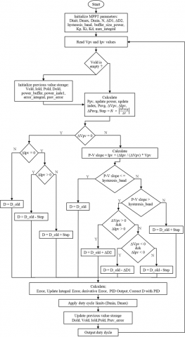
Figure 1 illustrates the overall block diagram of the proposed VSS-InCond with auxiliary PID correction. The system operates by measuring PV voltage and current, these input feed the VSS-InCond algorithm, which generates a primary duty cycle. Concurrently, the PID controller generates a correction signal based on the change in average power. This PID output is then scaled and summed with the VSS-InCond duty cycle. The resulting combined duty cycle signal drives the dc-dc converter, ensuring the PV array operates at the MPP. This integration combination the VSS-InCond’s fast tracking with the PID’s precise regulation and oscillation damping. This integrated approach aims for superior MPPT performance. Its effectiveness will be validated through extensive simulation results.
Figure 1. Proposed algorithm
The proposed algorithm integrates VSS and InCond and employs PID correction for power optimization in PV system, as illustrated in Figure 1. The operation of the proposed VSS-InCond PID MPPT algorithm systematically follows these steps in each control cycle.
a. Parameter initialization
The algorithm begins by initializing all necessary parameters, including the initial duty cycle, previous power and voltage value, PID parameters (gains, contribution factor, and integral wind-up limit). VSS factor, and hysteresis band. The duty cycle bounds are set to $D_{\min }=0.1$ and $D_{\max }=0.9$, which are crucial for maintaining converter stability and preventing undesired operational states.
b. PV measurement
The voltage (Vpv) and current (Ipv) from the PV array are measured, and the current PV power (Pcurrent) is calculated.
c. Incremental change calculation
The variation in power (∆P) and voltage (∆V) is computed based on current and previous values to determine ∆P/∆V.
d. Primary duty cycle adjustment (VSS-InCond)
Based on the ∆P/∆V value and Vpv, the VSS-InCond logic determines the orientation and extent of the initial duty cycle adjustment. The step size is dynamically adjusted.
e. PID correction calculation
A PID error is calculated from the change in power (∆P). Then, the PID correction output is computed using the defined gains and update based on the integral and derivative terms.
f. Duty cycle update
The PID correction is scaled and added to the primary duty cycle adjustment produced by VSS-InCond to obtain the new duty cycle.
g. Application of safety constraints
The updated duty cycle is ensured to be within safe bounds ($D_{\min }$ to $D_{\max }$) to maintain stability and protect the converter.
h. Data storage
Current power, voltage, and duty cycle values, as well as PID errors, are stored for use in the next control cycle iteration.
The flowchart commences with the initialization of MPPT parameters, followed by reading the output voltage and current value of the PV array and calculating the previous value storage. The previous value storage serves as a temporary memory of the previous values for the subsequent iteration. In each iteration, the algorithm reads the output voltage and current values of the PV array. Subsequently, the PV power is computed, and the incremental changes in voltage and current are determined based on the current and previous values. The initial step size for adjusting the duty cycle value is calculated based on the change in power with respect to the change in voltage.
The core of this algorithm lies in the implementation of the VSS and InCond logic. When voltage change occurs ($\Delta V_{p v} \neq$ 0), the slope of the power-voltage ($\mathrm{P}-\mathrm{V}$) curve is calculated. Based on the slope's value relative to the hysteresis band, and also based on the sign of $\Delta V_{p v}$ and $\Delta I_{p v}$, the duty cycle step size is varied. Whwn the operating point is distant from the MPP, a large step ize is utilized, conversely a smaller step size is adopted as the operatin point nears the MPP. To enhance dynamic performance and reduce steady-state errors, the output of the VSS and InCond logic is corrected using a PID controller. The error for the PID controller is derived from the slope of the P-V curve. This correction signal is then added to the duty cycle value generated by the VSS and InCond logic. After the PID is applied, the final duty cycle value is limited between $D_{\text {min }}$ and $D_{\text {max }}$ to ensure safe converter operation. the integration of VSS allows for an adaptive response to changes in operating conditions, while the PID correction provides finer adjustments and reduces the potential for oscillations around the MPP, thereby improving the overall system efficiency.
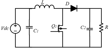
The DC-DC converter employed in this research is a boost converter type, and its equivalent circuit can be seen in Figure 2.
Figure 2. Boost converter equivalent circuit
Moreover, formulas (7)-(10) facilitate the determination of the boost converter’s component values [29].
$\frac{V_{\text {out }}}{V_{p v}}=\frac{1}{1-D}$ (7)
$C_1 \geq \frac{D}{8 \times f^2 \times L \times \Delta V_{i n}}$ (8)
$C_2 \geq \frac{D}{f \times R \times \Delta V_{o u t}}$ (9)
$L=\frac{D \times\left(1-D^2\right) \times R}{r \times f}$ (10)
The boost converter output voltage is $V_{\text {out }}$, the PV output voltage serving as the input to the boost converter is $V_{p v}, D$ is the duty cycle, $f$ is the frequency, $C_1$ and $C_2$ are the input and output capacitors of the boost converter, $L$ is the inductor, and $R$ is the load resistance. Furthermore, $r$ in Eq. (10) is the current ripple ratio with a value between 0.1 and 0.3. Based on formulas (7) through (10), the component values used are $C_1 =C_2=68\,\mathrm{uF}, L=2.2 \, \mathrm{mH}, R=68 \, \mathrm{Ohm}$, with a duty cycle of 0.6 and switching frequency of 10 kHz . Specifically, calculation for the capacitors based on desired ripple ratios yielded minimum required value of $34\,\mu\mathrm{F}$ for $C_l$ and $43.6\,\mu\mathrm{F}$ for $C_2$. As the design equations allow for values greater than or equal to these calculated minimums, $C_1=C_2=68\,\mathrm{uF}$ were chosen to provide an adequate safety margin, effectively reduce output ripple, and align with readily available commercial component size. In addition, for the boost converter to operate properly, the inductor must be designed for continuous conduction mode (CCM).
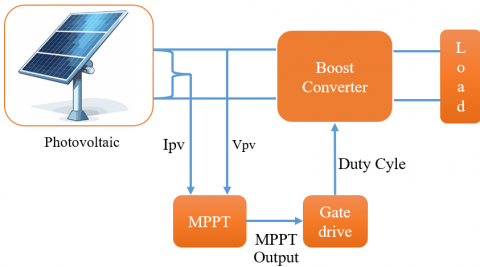
To confirm the efficacy of the proposed algorithm, a simulation-based methodology was employed. The system block diagram utilized in the simulation is depicted in Figure 3. Figure 3 illustrates the system used in this research, where the photovoltaic module is a monocrystalline type, Solana brand, Mono-24V-250W series, with a capacity of 24 V and 250 W, and the converter type used is a boost converter. The focus of this research is to enhance the system’s performance, thereby increasing the generated electrical power despite variations in irradiation and temperature. To conduct the simulation-based evaluation, the system model was developed and simulated using Simulink. A variable step solver, specifically ode45, was employed to effectively handle the system’s dynamics while ensuring numerical accuracy. Each simulation scenario was run for a total simulation time of 1 second. As a variable-step solver was utilized, the step size was automatically adjusted by the solver to optimize accuracy and computational efficiency based on the system’s dynamics. For the scope off simulation study, the boost converter model primarily focuses on the ideal behavior of its main components (L, C, R). This model does not explicitly incorporate parasitic elements, such as the equivalent series resistance of capacitors and the direct current resistance of the inductor or switching losses. This is to prioritize a clear evaluation of the proposed MPPT algorithm’s core performance in tracking the MPP and to maintain manageable simulation complexity.
Figure 3. System block diagram of the proposed research
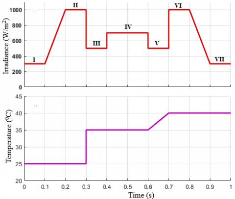
Figure 4. Irradiation pattern used
The testing scenario is divided into two parts: evaluating the system’s performance under changing irradiation conditions with a constant temperature (25℃) and under conditions where both irradiation and temperature vary simultaneously. The varying irradiation and temperature pattern are shown in Figure 4, where the irradiation changes are divided into seven distinct regions.
The proposed algorithm is an InCond algorithm combined with VSS and the utilization of a PID controller for improved duty cycle correction. To evaluate the effectiveness of the proposed algorithm’s performance, the simulation results are compared with those of a conventional algorithm and one that has been modified by previous researchers.
6.1 Performance analysis
The efficiency values presented in this section. Table 1 and Table 2 were calculated as the ratio of the simulated electrical power output to the ideal MPP power, using the Eq. (11).
Efficiency $(\%)=\frac{\text { Simulated } M P P \text { power }}{\text { Ideal MPP power }} \times 100$ (11)
These calculations were performed at each level of irradiation change after system reached a steady-state condition, ensuring an evaluation of the algorithm’s performance at specific operating point. Furthermore, it should be emphasized that the results presented in this study are derived from single-run simulation under predefined dynamic conditions. While these demonstrate clear comparative advantages, future work will involve extensive simulations with statistical analysis aiming to validate the algorithm’s robustness more comprehensively and thereby provide quantitative measure of variability.
Table 1. Performance comparison of MPPT algorithms under varying irradiation and constant temperature conditions
|
No. |
Regions |
MPPT Algorithm |
Power Overshoot (W) |
Power Undershoots (W) |
Steady-State Power Oscillation (W) |
Settling Time (S) |
Generated Power (W) |
Efficiency (%) |
|
|
Ideal MPP |
Simulated MPP |
||||||||
|
I |
I |
Conventional |
NA |
NA |
NA |
NA |
72.612 |
45 |
61.97 |
|
2 |
Modified [19] |
NA |
NA |
NA |
NA |
56 |
77.12 |
||
|
3 |
Proposed |
NA |
NA |
NA |
0.03 |
68 |
93.65 |
||
|
4 |
II |
Conventional |
NA |
NA |
7 |
NA |
250 |
214 |
85.6 |
|
5 |
Modified [19] |
NA |
NA |
10 |
NA |
250 |
100 |
||
|
6 |
Proposed |
NA |
NA |
3.3 |
NA |
250 |
100 |
||
|
7 |
III |
Conventional |
NA |
55.23 |
NA |
0.02 |
123.271 |
119 |
96.54 |
|
8 |
Modified [19] |
NA |
28.18 |
12 |
0.015 |
123 |
99.78 |
||
|
9 |
Proposed |
NA |
26.08 |
NA |
0.007 |
123.3 |
100 |
||
|
0 |
IV |
Conventional |
NA |
NA |
NA |
0.002 |
174.142 |
174 |
99.92 |
|
11 |
Modified [19] |
NA |
NA |
7 |
0.016 |
174 |
99.92 |
||
|
12 |
Proposed |
NA |
NA |
NA |
0.001 |
174.2 |
100 |
||
|
13 |
V |
Conventional |
NA |
8.65 |
NA |
0.015 |
123.271 |
119 |
96.54 |
|
14 |
Modified [19] |
NA |
NA |
12.3 |
0.0155 |
123 |
99.78 |
||
|
15 |
Proposed |
NA |
NA |
NA |
0.0008 |
123.3 |
100 |
||
|
16 |
VI |
Conventional |
65.5 |
NA |
7.02 |
0.013 |
250 |
215 |
86 |
|
17 |
Modified [19] |
NA |
NA |
9.5 |
0.0176 |
250 |
100 |
||
|
18 |
Proposed |
4 |
NA |
9.2 |
0.001 |
250 |
100 |
||
|
19 |
VII |
Conventional |
NA |
NA |
NA |
0.015 |
72.612 |
44.5 |
61.28 |
|
20 |
Modified [19] |
NA |
NA |
NA |
0.015 |
56 |
77.12 |
||
|
21 |
Proposed |
NA |
NA |
NA |
0.002 |
68 |
93.65 |
||
Note: *NA is not available.
Table 2. Performance comparison of MPPT algorithms under simultaneously varying irradiation and temperature conditions
|
No. |
Regions |
MPPT Algorithm |
Power Overshoot (W) |
Power Undershoots (W) |
Steady-State Power Oscillation (W) |
Settling Time (S) |
Generated Power (W) |
Efficiency (%) |
|
|
Ideal MPP |
Simulated MPP |
||||||||
|
I |
I |
Conventional |
NA |
NA |
NA |
NA |
72.612 |
45 |
61.97 |
|
2 |
Modified [19] |
NA |
NA |
NA |
NA |
55 |
75.75 |
||
|
3 |
Proposed |
NA |
NA |
NA |
0.03 |
68 |
93.65 |
||
|
4 |
II |
Conventional |
NA |
NA |
7.02 |
NA |
250 |
213 |
85.2 |
|
5 |
Modified [19] |
NA |
NA |
10 |
NA |
250 |
100 |
||
|
6 |
Proposed |
NA |
NA |
3.3 |
NA |
248.5 |
99.4 |
||
|
7 |
III |
Conventional |
NA |
94 |
NA |
0.01 |
123.271 |
116.2 |
94.26 |
|
8 |
Modified [19] |
NA |
42.4 |
7 |
0.01 |
117.35 |
95.20 |
||
|
9 |
Proposed |
NA |
16 |
7 |
0.025 |
117.5 |
95.32 |
||
|
0 |
IV |
Conventional |
NA |
NA |
NA |
0.01 |
174.142 |
165 |
94.75 |
|
11 |
Modified [19] |
NA |
NA |
NA |
0.01 |
166 |
95.32 |
||
|
12 |
Proposed |
NA |
NA |
NA |
0.002 |
168 |
96.47 |
||
|
13 |
V |
Conventional |
NA |
8.4 |
NA |
0.01 |
123.271 |
115 |
93.29 |
|
14 |
Modified [19] |
NA |
18 |
7 |
0.008 |
116 |
94.10 |
||
|
15 |
Proposed |
NA |
4 |
NA |
0.0012 |
116 |
94.10 |
||
|
16 |
VI |
Conventional |
44.5 |
NA |
7.05 |
0.014 |
250 |
189 |
75.6 |
|
17 |
Modified [19] |
10 |
NA |
9.3 |
0.0113 |
232.8 |
93.12 |
||
|
18 |
Proposed |
4.5 |
NA |
6.4 |
0.001 |
230 |
92 |
||
|
19 |
VII |
Conventional |
NA |
NA |
NA |
0.015 |
72.612 |
45 |
61.97 |
|
20 |
Modified [19] |
NA |
NA |
NA |
0.015 |
57.2 |
78.77 |
||
|
21 |
Proposed |
NA |
NA |
NA |
NA |
65 |
89.52 |
||
Note: *NA is not available.
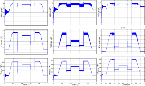
To test the performance of the proposed algorithm, the system depicted in Figure 3 was utilized. The performance under the testing scenario with varying irradiation and constant temperature can be observed in Figure 5. Figure 5 illustrated the simulation waveform result of the three algorithms across different subplots: (a) conventional InCond, (b) modified InCond, and (c) proposed algorithm, with detailed numerical comparisons provided in Table 1. In region I (300 W/m2 irradiation level), the power waveform using the conventional and modified algorithms exhibit significant oscillations (e.g., peak-to-peak oscillation of 31.7 W and 24.8 W) and do not reach convergence until the irradiation level increases to its maximum value. In contrast, the proposed algorithm demonstrates rapid convergence, achieving a stable MPP within approximately 0.03 s. Similarly, regarding steady-state oscillation, the proposed algorithm demonstrates significantly better performance in reducing oscillations, achieve a steady-state power ripple of only 9.2 W (highest in all radiation levels) compared to 7.02 W for the conventional and 12.3 W for the modified algorithm. However, despite having a slightly higher peak power ripple than the conventional method, the proposed algorithm consistently demonstrates superior performance in term of overall generated electrical power, which is clearly evident across the different regions as depicted in Figure 5. The voltage and current waveform for the proposed algorithm also exhibit faster stabilization and reduced fluctuation, directly contributing to the smoother power output.
A comprehensive comparison was conducted across all operating region (I-VII). The performance metrics evaluated included generated electrical power, overshoot, undershoot, steady-state oscillation, time to steady-state, and efficiency. For instance, at the irradiation level corresponding to Region VI, the conventional method yielded approximately 215 W, while both the modified and proposed methods achieved around 250 W. As detailed in Table 1. These comparisons consistently demonstrate the proposed algorithm’s outperforming the conventional and modified algorithms.
Figure 5. Simulation result comparison of (a) conventional InCond, (b) modified InCond [19], (c) proposed algorithm under varying irradiation and constant temperature conditions
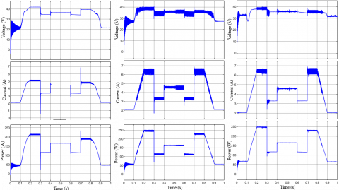
Figure 6 presents a performance comparison of the algorithms under simultaneously varying irradiation and temperature conditions, following the pattern shown in Figure 4. Similar to Figure 5, Figure 6 also illustrates (a) conventional InCond, (b) modified InCond, and (c) proposed algorithm for the three algorithms under these more complex dynamic conditions. The general performance patterns of the algorithms are largely similar to those displayed in Figure 5, with the proposed algorithm maintaining its superior tracking and oscillation damping capabilities. However, one notable difference observed in this scenario is a general decrease in generated electrical power due to combined effects of varying irradiation and temperature. Under these conditions, it is evident that an increase in temperature (e.g., in Region VI where temperature rises to 40℃) lead to a corresponding decrease in voltage, which is clearly confirmed by the simulation results (Figure 6, Region VI). A slight decrease in generated power also occurs in region V, but its magnitude is not significant compared to the overall trend. The proposed algorithm consistently exhibits advantages at low irradiation level (e.g., 300 W/m2), and the simulation results indicate that its performance is notably less affected by temperature variations under such conditions. This is evidenced in Region I and VII of both test conditions, where the test results show that the electrical power generated using the proposed algorithm is significantly better (e.g., generating 68 W more power at low irradiation than conventional methods) than that of the other algorithms. In terms of steady-state oscillation and overshoot, the proposed algorithm also consistently demonstrates considerably better performance. The highest oscillation value in Region III was 7 W for the proposed algorithm, 10 W for the modified algorithm in Region II, and 7.05 W for the conventional algorithm in Region VI. A detailed breakdown of the performance of each algorithm tested in this research can be found in Table 2.
6.2 Discussion on implementation aspects and limitations
While the proposed algorithm demonstrates robust performance in simulations, it is important to discuss certain practical considerations for its implementation. The auxiliary PID controller, crucial for enhancing tracking accuracy and oscillation dumping, relies on meticulously tuned gain parameters (KP, Ki, Kd). Although these gains were optimized through extensive simulation in this study, the tuning process for PID controllers can be inherently complex and sensitive in real-word applications. Achieving optimal performance in varying environmental conditions or with different PV system characteristics may require further fine-tuning, which could be a challenging aspect for broad applicability.
Furthermore, regarding computational requirements for real-time systems, the proposed method is designed to offer a more balanced solution between performance and computational efficiency compare to more complex AI-based MPPT schemes. The auxiliary PID correction adds a relatively minimal computational overhead compared to a pure InCond algorithm. However, for highly constrained embedded systems or very low-cost microcontroller, the additional calculations involved in the proportional, integral, and derivative terms of the PID controller should still be carefully considered. Optimization of the control code and selection of appropriate microcontroller hardware would be necessary to ensure efficient real-time implementation and avoid processing delays that could impact system performance.
Figure 6. Simulation result comparison of (a) conventional InCond, (b) modified InCond [19], (c) proposed algorithm under simultaneously varying irradiation and temperature conditions
The dynamic nature of solar radiation and thermal conditions critically influences the electrical power yielded by PV installations. Within this research, an innovative adaptive MPPT algorithm was developed, employing a variable step size strategy in conjunction with the InCond method and PID regulation. This aims to fine-tune the duty cycle, guided by the measured power change rate. Simulation outcomes demonstrate the proposed algorithm’s enhanced performance relative to conventional and modified counterparts. Specifically, it demonstrates improved ability in reducing steady-state oscillation and significantly enhances the generated electrical power. The algorithm also shows particular advantages at low irradiation levels, where it yields considerably higher electrical power output. Furthermore, the conducted tests suggest that the proposed algorithm maintains effective tracking and high-power output even under temperature variations, particularly at low irradiation levels, indicating less sensitivity to such changes. Despite these promising simulation results, it is important to acknowledge the inherent limitations of this study, primarily its reliance on simulation data. Future work will focus on experimental validation of the proposed algorithm using a physical PV system to confirm its performance in real-world conditions. This will include conducting extensive statistical analysis to further quantify its robustness and reliability, as well as exploring its applicability in more complex scenarios like partial shading conditions.
This research was supported by Department of Electrical Engineering, Universitas Andalas and Universitas Negeri Padang, West Sumatera, Indonesia.
[1] Le, A.V., Vu, L.T.T. (2025). Adaptive sliding mode control for maximum power point tracking in photovoltaic systems. Journal Européen des Systèmes Automatisés, 58(1): 31-38. https://doi.org/10.18280/jesa.580104
[2] Tawalbeh, M., Al-Othman, A., Kafiah, F., Abdelsalam, E., Almomani, F., Alkasrawi, M. (2021). Environmental impacts of solar photovoltaic systems: A critical review of recent progress and future outlook. Science of the Total Environment, 759: 143528. https://doi.org/10.1016/j.scitotenv.2020.143528
[3] Osman, A.I., Chen, L., Yang, M., Msigwa, G., et al. (2023). Cost, environmental impact, and resilience of renewable energy under a changing climate: A review. Environmental Chemistry Letters, 21(2): 741-764. https://doi.org/10.1007/s10311-022-01532-8
[4] Ali, M.H., Zakaria, M., El-Tawab, S. (2025). A comprehensive study of recent maximum power point tracking techniques for photovoltaic systems. Scientific Reports, 15(1): 14269. https://doi.org/10.1038/s41598-025-96247-5
[5] Malkawi, A.M., Odat, A., Bashaireh, A. (2022). A novel PV maximum power point tracking based on solar irradiance and circuit parameters estimation. Sustainability, 14(13): 7699. https://doi.org/10.3390/su14137699
[6] Katche, M.L., Makokha, A.B., Zachary, S.O., Adaramola, M.S. (2023). A comprehensive review of maximum power point tracking (MPPT) techniques used in solar PV systems. Energies, 16(5): 2206. https://doi.org/10.3390/en16052206
[7] Jalali Zand, S., Hsia, K.H., Eskandarian, N., Mobayen, S. (2021). Improvement of self-predictive incremental conductance algorithm with the ability to detect dynamic conditions. Energies, 14(5): 1234. https://doi.org/10.3390/en14051234
[8] Ramírez Torres, J.A., Lastres Danguillecourt, O., González Domínguez, R.A., Ibáñez Duharte, G.R., et al. (2025). Development and implementation of the MPPT based on incremental conductance for voltage and frequency control in single-stage DC-AC converters. Energies, 18(1): 184. https://doi.org/10.3390/en18010184
[9] Feroz Mirza, A., Mansoor, M., Ling, Q., Khan, M.I., Aldossary, O.M. (2020). Advanced variable step size incremental conductance MPPT for a standalone PV system utilizing a GA-tuned PID controller. Energies, 13(16): 4153. https://doi.org/10.3390/en13164153
[10] Chellakhi, A., El Beid, S., Abouelmahjoub, Y., Doubabi, H. (2024). An enhanced incremental conductance MPPT approach for PV power optimization: A simulation and experimental study. Arabian Journal for Science and Engineering, 49(12): 16045-16064. https://doi.org/10.1007/s13369-024-08804-1
[11] Chuang, M.T., Liu, Y.H., Ye, S.P. (2020). A novel variable step size incremental conductance method with an adaptive scaling factor. Applied Sciences, 10(15): 5214. https://doi.org/10.3390/app10155214
[12] Asnil, A., Nazir, R., Krismadinata, K., Sonni, M.N. (2024). Performance analysis of an incremental conductance MPPT algorithm for photovoltaic systems under rapid irradiance changes. TEM Journal, 13(2): 1087-1094.
[13] Shang, L., Guo, H., Zhu, W. (2020). An improved MPPT control strategy based on incremental conductance algorithm. Protection and Control of Modern Power Systems, 5(2): 1-8. https://doi.org/10.1186/s41601-020-00161-z
[14] Amir, A., Amir, A., Selvaraj, J., Rahim, N.A., Abusorrah, A.M. (2017). Conventional and modified MPPT techniques with direct control and dual scaled adaptive step-size. Solar Energy, 157: 1017-1031. https://doi.org/10.1016/j.solener.2017.09.004
[15] Isaloo, B.A., Amiri, P. (2016). Improved variable step size incremental conductance MPPT method with high convergence speed for PV systems. Journal of Engineering Science and Technology, 11(4): 516-528.
[16] Singh, J., Singh, S.P., Verma, K.S., Kumar, B. (2022). Comparative analysis of MPPT control techniques to enhance solar energy utilization and convergence time under varying meteorological conditions and loads. Frontiers in Energy Research, 10: 856702. https://doi.org/10.3389/fenrg.2022.856702
[17] Yüksek, G., Mete, A.N. (2023). A P&O based variable step size MPPT algorithm for photovoltaic applications. Gazi University Journal of Science, 36(2): 608-622. https://doi.org/10.35378/gujs.1050325
[18] Ali, M.M., Youssef, A.R., Ali, A.S., Abdel-Jaber, G.T. (2020). Variable step size PO MPPT algorithm using model reference adaptive control for optimal power extraction. International Transactions on Electrical Energy Systems, 30(1): e12151. https://doi.org/10.1002/2050-7038.12151
[19] Asnil, A., Krimadinata, K., Astrid, E., Husnaini, I. (2024). Enhanced incremental conductance maximum power point tracking algorithm for photovoltaic system in variable conditions. Journal Européen des Systèmes Automatisés, 57(1): 33-43. https://doi.org/10.18280/jesa.570104
[20] Saidi, K., Maamoun, M., Bounekhla, M.H. (2019). A new high performance variable step size perturb-and-observe MPPT algorithm for photovoltaic system. International Journal of Power Electronics and Drive Systems (IJPEDS), 10(3): 1662-1674. http://doi.org/10.11591/ijpeds.v10.i3.pp1662-1674
[21] Chai, Y.B., Pu, X. (2019). Variable step-size incremental conductance method used in PV power system. IOP Conference Series: Earth and Environmental Science, 295(4): 042006. http://doi.org/10.1088/1755-1315/295/4/042006
[22] Owusu-Nyarko, I., Elgenedy, M.A., Abdelsalam, I., Ahmed, K.H. (2021). Modified variable step-size incremental conductance MPPT technique for photovoltaic systems. Electronics, 10(19): 2331. https://doi.org/10.3390/electronics10192331
[23] Al-Wesabi, I., Fang, Z., Farh, H.M.H., Al-Shamma’a, A.A., Al-Shaalan, A.M. (2024). Comprehensive comparisons of improved incremental conductance with the state-of-the-art MPPT Techniques for extracting global peak and regulating dc-link voltage. Energy Reports, 11: 1590-1610. https://doi.org/10.1016/j.egyr.2024.01.020
[24] Alsumiri, M. (2019). Residual incremental conductance based nonparametric MPPT control for solar photovoltaic energy conversion system. IEEE Access, 7: 87901-87906. https://doi.org/10.1109/ACCESS.2019.2925687
[25] Triki, Y., Bechouche, A., Seddiki, H., Abdeslam, D.O. (2020). Unity efficiency and zero-oscillations based MPPT for photovoltaic systems. Applied Solar Energy, 56(2): 75-84. https://doi.org/10.3103/S0003701X20020127
[26] Goswami, Y., Rana, K.P.S., Kumar, V. (2021). Performance analysis of an improved variable step-size IC MPPT technique for SPV system. In 2021 International Conference on Computing, Communication, and Intelligent Systems (ICCCIS), Greater Noida, India, pp. 822-827. https://doi.org/10.1109/ICCCIS51004.2021.9397127
[27] Islam, H., Mekhilef, S., Shah, N.M., Soon, T.K., Wahyudie, A., Ahmed, M. (2021). Improved proportional-integral coordinated MPPT controller with fast tracking speed for grid-tied PV systems under partially shaded conditions. Sustainability, 13(2): 830. https://doi.org/10.3390/su13020830
[28] Sahoo, J., Samanta, S., Bhattacharyya, S. (2020). Adaptive PID controller with P&O MPPT algorithm for photovoltaic system. IETE Journal of Research, 66(4): 442-453. https://doi.org/10.1080/03772063.2018.1497552
[29] Asnil, A., Nazir, R., Krismadinata, K., Nasir, M. (2025). Comparative analysis of incremental conductance MPPT for enhanced algorithm performance. Indonesian Journal of Electrical Engineering and Computer Science, 37(3): 1415-1427. http://doi.org/10.11591/ijeecs.v37.i3.pp1415-1427