Aulia Ishak*![]() | Rosnani Ginting
| Rosnani Ginting![]() | Elsa Sri Erjuni Rumapea
| Elsa Sri Erjuni Rumapea![]() | Pramodkumar Kataraki
| Pramodkumar Kataraki![]() | Ahmad Faiz Zubair
| Ahmad Faiz Zubair![]()
© 2025 The authors. This article is published by IIETA and is licensed under the CC BY 4.0 license (http://creativecommons.org/licenses/by/4.0/).
OPEN ACCESS
The integration of reverse engineering (RE) and additive manufacturing (AM) in the design and development of prosthetic devices has emerged as a promising approach to improving personalization, production efficiency, and the overall quality of assistive medical technologies. This study reviews recent advancements in the combined use of RE and AM within the prosthetics field, focusing on methodologies employed and outcomes achieved in various research efforts. RE allows for the accurate digital capture of a patient's residual limb, which serves as the basis for creating customized prosthetic components. When combined with AM, which enables rapid prototyping and precise fabrication, the result is a highly tailored device that aligns with the user’s anatomical and functional needs. Findings from multiple studies indicate that this integration leads to improvements in mechanical performance, dimensional precision, and user satisfaction. Moreover, the use of AM reduces lead times and manufacturing costs, facilitating quicker access to prosthetic solutions, particularly beneficial in low-resource settings. However, challenges remain, including concerns over material biocompatibility, long-term durability, and the lack of standardized workflows and regulatory guidelines. These limitations highlight the need for continued research and interdisciplinary collaboration involving engineers, clinicians, and industry stakeholders. Advancing this integration further could revolutionize prosthetic care and significantly enhance the quality of life for individuals with limb differences.
additive manufacturing (AM), customization, prosthetics, reverse engineering (RE), biocompatibility
Lower limb amputation can occur due to various reasons, including congenital conditions where patients are born with missing limbs, as well as health-related issues such as Diabetes Mellitus or traumatic injuries [1]. These amputations or congenital defects disrupt the complex neural networks responsible for transmitting motor commands and sensory feedback between the brain and the affected limb. This disruption significantly impairs an individual’s ability to control movement and experience sensation, thereby severely affecting their daily functional capacity [2]. Compared to the general population, amputation has a negative impact on physical function, role performance, social interactions, vitality, and overall health [3].
Amputation is a medical intervention often undertaken as a result of traumatic injuries or chronic conditions, including complications from diabetes, severe infections, cancer, and other health issues. For patients with chronic illnesses, amputation serves as a preventative measure to halt the progression or spread of the disease to unaffected areas. This procedure commonly involves the removal of limbs such as arms, fingers, toes, legs (either above or below the knee), or other parts of the body [4].
Transtibial amputation, or the removal of the leg below the knee, is a significant cause of lower-limb disability. To compensate for limb loss, many patients utilize prosthetic devices to support physical activity. Among these, the below-knee prosthetic leg, commonly referred to as a prosthetic leg, is specifically designed for individuals with below-knee amputations. This device functions as a substitute for the natural leg, aiming to enhance the user’s quality of life and mitigate the economic challenges associated with amputation. Compared to other assistive devices such as wheelchairs, walking sticks, and crutches, below-knee prosthetic legs offer superior flexibility and adaptability for individuals with this type of disability [5].
Prosthesis rejection remains a significant challenge in the rehabilitation of amputees. The research highlights that prioritizing personalized prosthetic quality, tailored to meet individual user needs, plays a crucial role in achieving successful fitting, extending prosthesis usage, and reducing rejection rates. Therefore, creating affordable and easily customizable prosthetic devices is crucial to enhancing the quality of life for individuals living with limb impairments [6].
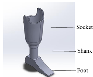
A transtibial or below-knee prosthetic leg is an assistive device designed to replace lower limbs lost due to amputation or congenital conditions. It comprises three primary components: the socket, shin tube (pylon or shank), and foot. However, many amputees in North Sumatra face financial barriers preventing them from acquiring or utilizing prosthetic legs. Traditional sockets, produced using plaster molding techniques, typically weigh between one and two kilograms. Patients have reported these sockets to be excessively heavy, particularly when combined with the need to use walkers for mobility. The introduction of 3D-printed lower-limb socket prosthetics offers a promising alternative by reducing costs and production time while enabling easy customization for user comfort. These sockets weigh between 1.5 and 3 kilograms and can be tailored to fit individual sizes, providing a more practical and user-friendly solution [7]. The specifications of transtibial prosthetic foot will be shown in Figure 1.
Figure 1. Specifications of transtibial prosthetic foot
Based on Figure 1, transtibial prosthetic foot can be divided into socket, shank/pylon, and foot. Socket is a part to connect between the stump for the amputees to the prosthetic. Shank is a part of transtibial prosthetic foot that act as a buffer, while foot is basically made from softer material such as silicon. A preliminary study was conducted using the Prosthetic Evaluation Questionnaire (PEQ), with certain adjustments, to identify challenges faced by respondents. Number of respondents in this research is based on judgement sampling, where sampling is taken on elements of population that relates to the objective of the research. The evaluation focused on below-knee prosthetic leg products commonly available and used in Indonesia, particularly among individuals from middle to lower socioeconomic backgrounds. These prosthetics are typically constructed with High-Density Polyethylene (HDPE) as the primary material. Similar evaluations of prosthetic leg products using questionnaires will be validated using Pearson correlation and Alpha Cronbach coefficient.
Based on an evaluation involving 20 respondents who use below-knee prosthetic legs, various complaints and issues were identified during prosthetic usage. The detailed results of this evaluation are presented in Figure 2.
Figure 2. PEQ questionnaire respondent evaluation results
The evaluation results indicated that respondents did not report significant issues with the current transtibial prosthetic leg products. This conclusion is supported by utility, appearance, and limb health scores that exceeded the minimum threshold. However, these results may reflect the respondents' limited exposure to or knowledge of alternative prosthetic foot products.
The preliminary study using the PEQ identified at least 12 types of issues encountered by users of I-5 prosthetic foot products. Among these, the most frequently reported issue was the occurrence of blisters at the stump-socket interface, which was noted in 10 instances.
The challenge of ensuring that prosthetic legs are easy to fit Their study aimed to design a simplified prosthetic leg product that is both user-friendly and cost-effective on improving the shank or pylon of prosthetic legs to make the products lighter and more functional.
Based on Figure 2, the flexibility of the material and the satisfaction of the product still has negative scoring. Figure 3 shows stump of the amputees can be wounded due to bad material and invalid measurement. To date, most efforts to improve or redesign transtibial prosthetic legs have focused on enhancing specific components without considering the prosthesis as an integrated system. Addressing this issue, the reverse engineering method has been employed as a comprehensive approach. Reverse engineering involves analyzing existing products to inform the design of similar products, with the aim of minimizing weaknesses while enhancing strengths [8].
This method is particularly valuable in product development, as it helps reduce production costs and improve the quality of the final product [9, 10]. Reverse engineering is advantageous because it enables rapid product development [11], facilitates the creation of health products tailored to patient needs, and enhances measurement accuracy and prosthesis modeling through data acquisition processes, such as scanning [12].
Figure 3. Stump of scars
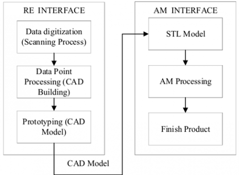
The integration of reverse engineering and additive manufacturing methods in problem solving with the implementation steps of both methods in this study are presented in Figure 4.
Figure 4. Integration steps of RE and AM methods
Based on Figure 4, there are several steps of the integration between reverse engineering and additive manufacturing:
Additive manufacturing (AM) interfacing is the stage to print the CAD Model already designed in the previous stage in STL File format. The CAD Model printing process is fully implemented by the 3D Printing machine until it reaches the finished product stage [13].
3.1 Measurement
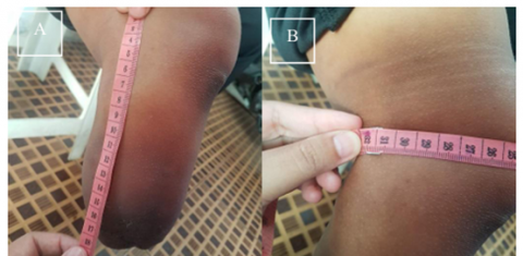
Manual measurement was conducted to verify the size obtained digitally through 3D scanning and ensure that the digitally recorded size was the same as the manual measurement.
Figure 5. Stump length measurement (A); Stump diameter measurement (B)
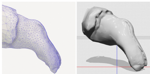
Figure 6. User stump scan result
Based on Figure 5, the manual measurement was conducted by measuring two parts of the stump, which are stump length and stump diameter. To verify the result, digital measurements were performed to capture detailed data points, dimensions, and a three-dimensional representation of the stump. These measurements were obtained using the LIDAR (Light Detection and Ranging) technique, facilitated by an iPhone and the PolyCAM application. The results of the three-dimensional scan of the stump are shown in Figure 6, with the scan producing a total of 2,353.90 data points recorded using the PolyCAM application.
3.2 Reverse engineering
3.2.1 Data digitalization (scanning process)
This stage aims to find out the patient's main data such as foot size and stump shape, in addition to size, the patient's daily activities are also observed such as riding a motorcycle or going up and down small stairs. The shape of the stump in each patient has a personal size, to get good data, a 3D scanner must be used and processed into digital data as shown in Figure 7.
Figure 7. Digital data from 3D scanning with PolyCAM
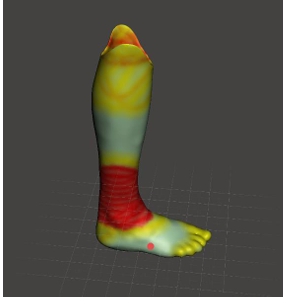
To validate the accuracy of the PolyCAM scan, manual anthropometric measurements were performed at key anatomical landmarks (e.g., stump circumference, residual limb length) and compared with the corresponding dimensions in the 3D model. The average deviation was ±1.5 mm, which is considered acceptable for prosthetic applications [14]. It is also important to note that the anatomical shape of residual limbs can vary significantly between individuals with disabilities. Additionally, scanner accuracy may vary depending on the size and geometry of the scanned body segment [15].
3.2.2 Data point processing (CAD building)
The design concept development for the transtibial prosthetic leg was undertaken by referencing the shape of the user's left leg. In this process, the scans of the user’s left foot were refined using the Meshmixer application to sculpt and finalize the prosthetic leg design. Meshmixer was used for smoothing, surface patching, and mesh repair. In this process, the scans of the user's left foot were refined using the Meshmixer application to sculpt and finalize the prosthetic leg design. The results of this embodiment design stage are illustrated in Figure 8.
Figure 8. Transtibial prosthetic foot sculpting result design
Simplification of the design form of the prosthetic leg was applied to facilitate the 3D printing process to be carried out. The design simplification was implemented on the recommendation of 3D printer users in Medan city due to the unavailability of a proper 3D printer to print a full prosthesis leg. The temporary design of transtibial prosthetic foot will be shown in Figure 9.
Figure 9. Transtibial prosthetic foot temporary design
Topology optimization was not explicitly applied to the socket design, as the shape was directly derived from the scanning and sculpting of the user’s stump. However, to ensure the structural integrity of the design, a static load simulation was conducted using SolidWorks Simulation software with the Von Mises stress analysis method. A vertical load of 1000 N was applied to the socket, based on the reference maximum body mass that the design is expected to accommodate, which is 100 kg [15].
Detail design of socket on transtibial prosthetic foot will be shown in Figure 10.
Figure 10. Socket temporary design
3.3 Prototyping
Based on the detailed design process that has been carried out by applying topology optimization simulations, the final design of the transtibial prosthetic leg is obtained as shown in Figure 11.
Figure 11. Transtibial prosthetic foot final design
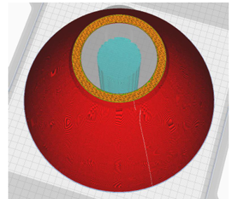
The dimensions of the final design of the transtibial prosthetic leg in p × l × t are 24 × 15 × 24 cm. The final design of the prosthetic leg is then used as input in the additive manufacturing process to see if the final design can be produced with 3D printing technology. The sliced model shown in Figure 12.
Figure 12. STL model socket after slicing
3.4 Additive manufacturing
Once the optimal or "best" design was finalized, the next step was to implement the design using a 3D printer. The 3D printer employed was the "Prusa I4 Sunhokey" model, utilizing the Fused Deposition Modeling (FDM) technique. The use of this type of 3D printer involves two main stages: the modeling stage and the printer setup stage.
In the modeling stage, 3D printing software such as "Ultimaker Cura" is used. Initially, the software must be configured according to the specifications of the printer, including the bed dimensions, nozzle size, number of extruders, and other relevant settings. Following this, the model to be printed is created, either directly within the software or imported from CAD software. The next step involves defining the model's parameters, such as the material type, printing pattern, wall thickness, model density, printing speed, and others. Once these parameters are set, the software provides guidance on the appropriate printer settings, including nozzle and bed temperatures.
The 3D printing process for the foot design was carried out using the following specified printing parameters:
Layer thickness: 0.22 mm.
Nozzle and bed temperature: 60℃.
Infill density: 11.42%.
Infill pattern: Gyroid.
The application of these parameters was obtained through discussions with 3D printing service providers. The filaments used to print the current design are Polylactic Acid (PLA).
3.5 Final product design
The design process for a transtibial prosthetic leg starts with manual measurements using a body meter, complemented by digital measurements through LIDAR-based 3D scanning applications, such as PolyCAM and KIRI Engine, on an iPhone. The choice of these applications is supported by Askar and Sternberg [16], which indicates that both applications produce digital models with minimal error compared to other alternatives. The scanning data was used as the basis for making the initial design of the prosthetic leg [16].
The next step involved creating a CAD model of the prosthetic foot using the VDI 2221 method. This process began with the classification of design tasks, such as fit, curvature, slight design, and interchangeability, which were defined through consultations with prosthetic orthotics experts. The design model was based on the shape of the user's left foot and served as the foundation for further development.
Initially, the design concept was planned as an exoskeletal structure, allowing the entire prosthetic leg to be printed without the need for assembly. However, due to limitations in 3D printing services available in Medan, the design was modified to an endo skeletal model. This revision offered the advantage of allowing damaged parts to be replaced individually, rather than replacing the entire prosthesis, based on feedback from the prosthetic orthotist. On the other hand, the transition from exoskeletal to endoskeletal designs presents several challenges. One of the main issues is giving irritation and potential infections to the stump. Material selection is crucial, with metals, polymers, and carbon fibers commonly used while prosthetic designs must consider functional requirements on movement freedom [17].
The initial exoskeletal design aimed for a fully 3D-printed, assembly-free structure. However, due to limitations in Medan’s 3D printing infrastructure, the design was revised to an endoskeletal model, enabling modular replacement of damaged components—a recommendation from the prosthetist. For material selection, PLA+ was chosen for its balanced mechanical properties, suitability for lightweight prosthetics, and consistent printability. PLA+ offers superior flexibility, impact resistance, and thermal stability compared to standard PLA [18]. Its low cytotoxicity and proven use in non-invasive orthotic applications addressed biocompatibility concerns. However, for long-term durability in extreme conditions, alternatives like Nylon CF or TPU may be explored. Notably, PLA has demonstrated promising tensile and structural performance in transtibial sockets [19].
The provisional prosthetic leg design met the minimum standards required for supporting the user's ability to walk and stand. However, the initial design weight of 1,865 grams exceeded the target maximum weight of 2,000 grams. To address this, a topology optimization simulation was performed with the goal of reducing the weight by up to 80%. A topology simulation is used to reducing weight. By doing this simulation, it can save material to the maximum number. As a result, the final weight of the design was reduced to 373 grams, in line with research, which suggested an 80% weight reduction for design efficiency [15].
The prosthetic leg design after topology optimization should have good structural integrity. Therefore, stress analysis simulations were carried out to validate the structural integrity of the design. The stress analysis simulation was carried out with Von-Misses simulation which showed values ranging from 8.450e-04 to 2.6988e+0.6 N/m2 with the amount of force applied to the design is 1000 N. The application of a force value of 1000 N is based on the research of which assumed that the maximum mass that can be accommodated by the design is 100 kg [15].
The application of both methods in prostheses in other studies showed a reduction in weight and effort expended. PratimaSarangi and Nayak’s study showed a lightweight prosthetic weighing 256 grams while reducing manufacturing time compared to traditional methods [20].
The resulting provisional prosthetic design was implemented and tested using a comfort survey. The provisional product design provided comfort in a more even spread of pressure in comparison. The aesthetics of the provisional prosthetic design can be customized due to the use of 3D printing whereas customization is limited to traditional prosthetics. The weight of the traditional design is heavier with high cost compared to the proposed design with light weight and lower cost.
The comparison between conventional prosthetic leg and 3D printing based prosthetic leg is on several factors, such as cost and production time. According to the doctor and engineer that were interviewed, conventional prosthetic leg’s production can take 3 days of production time, while the 3D printing based prosthetic leg only take around 24 hours (assuming the 3D printing machine is not turned off). This long production time gives an effect to increasing cost to around Rp4,000,000 while 3D printed prosthetic leg only cost half of it. The usage of PolyCAM to scan the stump of the amputee makes 3D printed product has shorter time of production and cheaper cost.
The process of improving the design of the transtibial prosthetic leg was carried out through reverse engineering and additive manufacturing. The steps started with scanning the user's stump to obtain the shape and dimensions as the basis of the design. The design was created using the VDI 2221 and Topology Optimization methods to achieve an optimal shape, then converted to STL format for 3D printing. The printing process uses polylactic acid material with appropriate infill pattern settings and parameters. The designed prosthetic leg consists of three parts: foot, shank, and socket, with dimensions of 24 × 15 × 24 cm after assembly. 3D printed prosthetic leg production cut the weight by 375 grams with only 3 days of production time and reduce the price for half of the initial prosthetic leg.
However, due to variation of customer requirement because of different types of amputation on the patient, makes this research have a small sample size and the production can only be categorized as Make to Order type of production. Clinical trials for this new prosthetic leg should be conducted in the near future to make sure product can be comfortable and usable by patient.
The authors would like to express their gratitude and appreciation to the Master of Industrial Engineering, University of North Sumatra for the opportunity and financial support provided to carry out this research.
[1] Han, G., Ceilley, R. (2017). Chronic wound healing: A review of current management and treatments. Advances in Therapy, 34: 599-610. https://doi.org/10.1007/s12325-017-0478-y
[2] Wheaton, L.A. (2017). Neurorehabilitation in upper limb amputation: Understanding how neurophysiological changes can affect functional rehabilitation. Journal of Neuroengineering and Rehabilitation, 14: 1-12. https://doi.org/10.1186/s12984-017-0256-8
[3] Eiser, C., Darlington, A.S.E., Stride, C.B., Grimer, R. (2001). Quality of life implications as a consequence of surgery: Limb salvage, primary and secondary amputation. Sarcoma, 5(4): 189-195. https://doi.org/10.1080/13577140120099173
[4] Suryawan, D., Ridlwan, M., Setiadi, A. (2019). Inovasi desain dan simulasi model prostesis bawah lutut berdasarkan antropometri orang indonesia. Jurnal Teknik Mesin Indonesia, 14(1): 30-36. https://doi.org/10.36289/jtmi.v14i1.112
[5] Fitrianto, T.R., Dharmastiti, R. (2019). Evaluasi produk kaki prostetik bawah lutut berdasarkan persepsi pengguna usia 15-64 tahun. Prosiding Sains Nasional dan Teknologi, 1(1).
[6] Østlie, K., Lesjø, I.M., Franklin, R.J., Garfelt, B., Skjeldal, O.H., Magnus, P. (2012). Prosthesis rejection in acquired major upper-limb amputees: A population-based survey. Disability and Rehabilitation: Assistive Technology, 7(4): 294-303. https://doi.org/10.3109/17483107.2011.635405
[7] Masykur, L.A., Suryawan, D. (2021). Desain dan simulasi socket prostesis bawah lutut dengan variasi material berbasis komposit. JTT (Jurnal Teknologi Terapan), 7(2): 153-160. https://doi.org/10.31884/jtt.v7i2.337
[8] Babić, M., Verić, O., Božić, Ž., Sušić, A. (2019). Fracture analysis of a total hip prosthesis based on reverse engineering. Engineering Fracture Mechanics, 215: 261-271. https://doi.org/10.1016/j.engfracmech.2019.05.003
[9] Asadizanjani, N., Tehranipoor, M., Forte, D. (2017). PCB reverse engineering using nondestructive X-ray tomography and advanced image processing. IEEE Transactions on Components, Packaging and Manufacturing Technology, 7(2): 292-299. https://doi.org/10.1109/TCPMT.2016.2642824
[10] Valerga, A.P., Batista, M., Bienvenido, R., Fernández-Vidal, S.R., Wendt, C., Marcos, M. (2015). Reverse engineering based methodology for modelling cutting tools. Procedia Engineering, 132: 1144-1151. https://doi.org/10.1016/j.proeng.2015.12.607
[11] Dúbravčík, M., Kender, Š. (2012). Application of reverse engineering techniques in mechanics system services. Procedia Engineering, 48: 96-104. https://doi.org/10.1016/j.proeng.2012.09.491
[12] Telea, A.C. (Ed.). (2012). Reverse Engineering: Recent Advances and Applications. InTech, Croatia.
[13] Kumar, A., Kumar, P., Singh, H., Haleem, A., Mittal, R.K. (2023). Integration of reverse engineering with additive manufacturing. In Advances in Additive Manufacturing, pp. 43-65.
[14] Koepke, A., Lafarge, T., Possolo, A., Toman, B. (2017). Consensus building for interlaboratory studies, key comparisons, and meta-analysis. Metrologia, 54(3): S34. https://doi.org/10.1088/1681-7575/aa6c0e
[15] Mansour, H.A., Abdullah, H.N. (2022). Design and implementation of remote evaluation system for the prosthetic limbs. In 2022 3rd International Conference for Emerging Technology (INCET), Belgaum, India, pp. 1-7. https://doi.org/10.1109/INCET54531.2022.9824666
[16] Dessery, Y., Pallari, J. (2018). Measurements agreement between low-cost and high-level handheld 3D scanners to scan the knee for designing a 3D printed knee brace. PloS One, 13(1): e0190585. https://doi.org/10.1371/journal.pone.0196183
[17] Askar, C., Sternberg, H. (2023). Use of smartphone lidar technology for low-cost 3D building documentation with iPhone 13 pro: A comparative analysis of mobile scanning applications. Geomatics, 3(4): 563-579. https://doi.org/10.3390/geomatics3040030
[18] Aschoff, H.H., McGough, R.L. (2012). The Endo-Exo Femoral Prosthesis: A new rehabilitation concept following above knee amputation. Orthopaedic Proceedings, 94(SUPP_XXXIX): 77-77. https://doi.org/10.1302/1358-992X.94BSUPP_XXXIX.BOA2011-077
[19] Rochlitz, B., Pammer, D. (2017). Design and analysis of 3D printable foot prosthesis. Periodica Polytechnica Mechanical Engineering, 61(4): 282-287. https://doi.org/10.3311/PPme.11085
[20] van der Stelt, M., Verhamme, L., Slump, C.H., Brouwers, L., Maal, T.J. (2022). Strength testing of low-cost 3D-printed transtibial prosthetic socket. Proceedings of the Institution of Mechanical Engineers, Part H: Journal of Engineering in Medicine, 236(3): 367-375. https://doi.org/10.1177/09544119211060092