Khalid M. Sowoud*![]() | Balsam H. Abed
| Balsam H. Abed![]() | Emad Q. Hussein
| Emad Q. Hussein![]()
© 2025 The authors. This article is published by IIETA and is licensed under the CC BY 4.0 license (http://creativecommons.org/licenses/by/4.0/).
OPEN ACCESS
The aeroelastic phenomenon of flutter poses significant challenges in aircraft design, requiring careful consideration of multiple parameters to ensure stability. This study investigates the combined effects of sweep angle, flap angle and taper ration on flutter speed. The motion equations are derived in 3D using bending and torsional mode coupling, with aerodynamic forces influenced by the aforementioned geometric parameters. Numerical simulations are performed in MATLAB to predict flutter speed across a wing configuration, and the results are compared to existing theoretical research to ensure accuracy. The researchers discovered that increasing the sweepback angle from 0° to 50° significantly improved flutter speeds with gains of up to 15-25% depending on wing configurations. Conversely, increasing the flap angle consistently reduces flutter speed, with a 10-20% reduction. The taper ratio causes a slight but noticeable increase in flutter speed, contributing to a 5-10% improvement. This study provides a comprehensive framework for understanding flutter phenomena, resulting in safer and more efficient wing design.
aeroelasticity, sweep angle, flap angle, taper ratio, aerodynamic, MATLAB
Flutter is a dynamic instability caused by the interaction between aerodynamic forces, structural bending and torsional motions in an aircraft wing. When the bending and torsional motion couple, the wing exhibits an oscillatory motion, and at a certain speed called the flutter speed, the energy exchange between the modes becomes self-sustaining leading to catastrophic structural failure if not controlled [1]. Flutter represents a critical challenge in the design and operation of aircraft wings, characterized by the interaction between aerodynamic forces and structural dynamics. It is a dynamic instability that can lead to catastrophic failure if not adequately addressed. Historically aircraft designers have sought to understand the underlying mechanism that contribute to flutter to enhance safety and performance [2]. The analysis of flutter characteristics in aircraft wings with varying configurations reveals significant insights into the relationship between wing design and aeroelastic behavior. The configuration of an aircraft wing particularly its taper ratio, and sweep angle plays a pivotal role in determining its aerodynamic properties and dynamic response. Taper ratios affect the distribution of lift and structural stiffness, while sweep angles influence the aerodynamic center and overall performance at high speed [3]. Previous studies have suggested that backward swept wings may demonstrate superior flutter characteristics compared to their forward swept counterparts although empirical data and comprehensive modeling are often lacking in this research, we develop a robust mathematical model that incorporates unsteady aerodynamic forces and structural dynamics to analyze the flutter behavior of wing with varying configuration [4-6]. The model utilizes aerodynamic integrating aerodynamic forces with structural properties to predict flutter speed across different taper ratios and sweep angles. Previous research has looked into the flutter problem; with an emphasis on its importance in aircraft design configuration [7-10]. It describes how variables such as aspect ratio and sweep angle affect flutter speed and stability. The primary goal of this study is to investigate the effects of sweep angle, flap angle, and taper ratio on wing flutter speed. The study aims to understand how geometric factors affect aeroelastic stability thoroughly. The goal is to create a predictive framework that will assist designers in optimizing wing configuration for improved flutter performance, resulting in safer and more efficient aircraft designs. Furthermore, this study intends to fill gaps in the existing literature by performing quantitative and comparative analyses of flutter speed under various wing configurations. This study is unique because it takes a comprehensive approach to analyzing the combined effects of sweep angle, flap angle, and taper ratio on flutter speed, which has never been done before. This study brings together these critical parameters to reveal their interdependence and combined effect on aeroelastic stability.
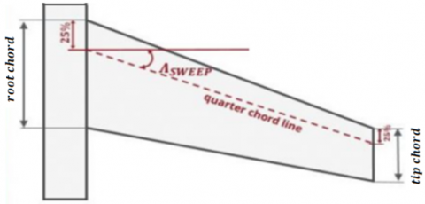
Flutter is a dynamic instability caused by the interaction of aerodynamic forces (lift and moment), inertial forces (mass and stiffness) and structural flexibility (bending and torsion) [11, 12]. For a swept wing as shown in Figure 1, the bending mode (in the vertical direction) and the torsional mode (twisting about the longitudinal axis) are coupled due to the aerodynamic forces, especially in swept wings.
Figure 1. The sweep angle of the aircraft Boeing 747 [13]
The governing equations of motion for flutter analysis can be represented as a system of coupled second order differential equation in bending and torsion. Here's a mathematical model based on the standard ceroplastic formulation with the inclusion of sweep angle, flap angle and taper ratio. The bending mode primarily describes the vertical displacement of the wing [7]:
$M_b \ddot{W}+C_b \dot{W}+K_b W=L_{\text {aero }(W, \alpha)}$ (1)
where, Laero(w,α) is the aerodynamic lift force which depends on the bending displacement, the torsional angle and the wing parameters. The torsional mode primarily describes the rotation of the wing around its longitudinal axis:
$I_t \ddot{\theta}+C_t \dot{\theta}+K_t \theta=M_{\text {aero }}(W, \alpha)$ (2)
where, Maero(w,α) is the aerodynamic pitching moment which depends on both bending displacement and the torsional angle.
The aerodynamic lift force and the pitching moment are dependent variables that are influenced by bending displacement, torsional angle, and additional parameters such as sweep angle, flap angle, and taper ratio. The lift force, which is categorized as an aerodynamic force and represented by [14, 15]:
$L_{{aero }}=\frac{1}{2} \rho V^2 S\left(C_{L o}+C_{L \alpha} \alpha+C_{L w} \frac{w}{C}+C_{L \delta} \delta\right)$ (3)
where, CL0, CLα, CLw, CLδ are lift coefficients that are contingent upon the angle of attack, bending displacement, and flap angle. The aerodynamic moment, commonly referred to as the pitching moment, can be expressed by
$M_{ {aero }}=\frac{1}{2} \rho V^2 SC\left(C_{M o}+C_{M \alpha} \alpha+C_{M w} \frac{w}{C}+C_{M \delta} \delta\right)$ (4)
where, CMo, CMα, CMw, CMδ are the pitching moment coefficients, which depend on the same variable as the lift coefficients. The sweep angle (Λ) is the angle between the lateral axis of the wing and a line parallel to the leading-edge. For swept wing, the effective angle of attack (α) decreases by a factor of cos(Λ). This means that the aerodynamic forces driving both the bending and torsional modes are reduced in the coupled equations, this modifies the aerodynamic force terms as [16]:
$C_L(\alpha+\theta) \rightarrow \frac{C L(\alpha+\theta)}{\operatorname{Cos}(\Lambda)}$
$C_M(\alpha+\theta) \rightarrow \frac{C M(\alpha+\theta)}{\operatorname{Cos}(\Lambda)}$
The flap angle (δ) refers to the deflection of control surface like ailerons or flaps attached to the wing. The flap deflection increases the lift by CL and moment by CM. This introduces additional terms CL(α+θ+δ) and CM(α+θ+δ). Flap deflection changes the overall stability, especially in the torsional modes, as it increases the moment arm for aerodynamic forces on the wing, as illustrated in the parameters within Eq. (3) and in Eq. (4). The taper ratio (λ) refers to the relationship between the length of the wingtip chord and the chord length of the entire wing. This ratio plays a significant role in determining the stiffness and mass distribution throughout the wing. As the taper ratio changes, it alters the structural stiffness parameters in both the bending and torsional equations (Kb(λ) and Kt(λ)). These modifications subsequently influence the natural frequencies related to bending and torsional modes. The coupling between the bending and torsional modes is induced by the aerodynamic forces acting on the wing. The interaction term comes from the angle of attack which depends on both the bending displacement w(t), and the torsional displacement θ(t). The effective angle of attack(αeff) for each section of the wing is [17]:
$\alpha_{e f f}=\alpha+\frac{d \omega}{d x}+\theta$ (5)
This term enters both the bending and torsion equations, causing the coupled dynamic behavior.
This interaction can be mathematically modeled by coupled differential equations representing the bending and torsional dynamic of the wing. For swept wings, flap angle and taper radios, the coupling between bending (vertical flexural deformation) and torsional (rotational deformation about the longitudinal axis) becomes more pronounced due to the aerodynamic and structural effects of these parameters [18, 19]. To represent the interrelated bending and torsional modes in three-dimensional space, the equations of motion may be integrated into a matrix formulation denoted by
$\left(\begin{array}{cc}M_b & 0 \\ 0 & I_t\end{array}\right)\binom{\ddot{w}}{\ddot{\theta}}+\left(\begin{array}{cc}C_b & 0 \\ 0 & C_t\end{array}\right)\binom{\dot{w}}{\dot{\theta}}+\left(\begin{array}{cc}K_b & 0 \\ 0 & K_t\end{array}\right)\binom{w}{\theta}=\left(\begin{array}{cc}L_{\text {aero }} & (w, \alpha) \\ M_{\text {aero }} & (w, \alpha)\end{array}\right)$ (6)
The flutter speed arises when these two modes become synchronously coupled, leading to an unstable response. To find the flutter speed, we need to solve this coupled system of equation. The critical flutter speed is determined when the system becomes dynamically unstable. By incorporating these parameters (sweep angle, flap angle and taper ratio) we can express the flutter speed as [20]:
$V_f(\alpha, \delta, \lambda)=\frac{1}{\cos (\Lambda)} \sqrt{\frac{2\left(K_b+K_t\right)}{\rho S\left(C_{L o}+C_{L \delta} \delta\right) C\left(\frac{k_t}{K_b}+\frac{M_b}{M_t}\right)}}$ (7)
where, $f(\lambda)$ is an empirically or analytically derived function accounting for the variation of mass and stiffness along the span.
To validate the current study's findings on the simulator flutter speed vs. sweep angle plot, theoretical results from previous studies were compared [21]. Figure 2 depicts this using the same parameters used for aircraft wings; the method is based on the 2D theory for a swept-back wing with a taper ratio of 0.5. Both simulated and theoretical flutter speed increase with sweepback angle, indicating a consistent upward trend. As the sweep angle increases, the simulated flutter speed appears to rise faster than the theoretical speed, with only a minor deviation at sweep angles greater than 40 degrees. There is a small difference between the theoretical and simulation results, particularly at higher sweep angles. This could be due to model simplification or differing assumptions (for example, coupling and damping). In most cases, the simulated flutter speed is close to the theoretical values, and good agreement is reported across the sweep angle range.
Figure 2. Comparison of theoretical and simulated flutter
This study will provide clarification on the main findings of our investigation into aeroelastic parameters. The 3D representation of flutter speed is based on three different aerodynamic parameters: sweep angle, flap angle, and taper ratio, all of which have a significant impact on the wing's flutter characteristics. We have tailored the analysis of the system parameters to a specific aircraft, as detailed in Table 1 [22].
Table 1. Realistic parameters for aircraft flutter estimation
|
Wing Geometric Properties |
|
|
Wing span length |
10 m |
|
Chord length |
2 m |
|
Wing reference area |
12 m² |
|
Taper ratio |
0.6 to 1 |
|
Sweepback angle |
0° to 50° |
|
Aerodynamic Properties |
|
|
Air density |
1.122 kg/m³ |
|
Cruise speed |
180 m/s |
|
Lift coefficient |
0.6 |
|
Lift curve slope |
4.5 per rad |
|
Incremental lift coefficient |
0.05 per deg |
|
Structural Properties |
|
|
Bending stiffness |
5×10⁶ N/m |
|
Torsional stiffness |
1×10⁶ Nm/rad |
|
Moment of inertia |
5000 kg m2 |
|
Unit mass/area of wing |
100 kg/m2 |
|
Young's modulus |
70 GPa |
|
Shear modulus |
30 GPa |
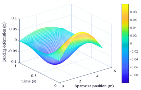
The interaction between bending and torsional modes, especially when considering parameters like sweep angle, flap deflection and taper ratio, leads to complex dynamic behavior in aircraft wings. These parameters directly affect the aerodynamic forces, changing how the bending and torsional stiffness interact. This coupling of bending and torsional modes plays a critical role in determining the stability of an aircraft wing and understanding this relationship helps in the design and analysis of safe, efficient wings. The 3D plot bending deformation and torsional deformation of an aircraft wing over time, as showing in Figures 3 and 4. These visualizations are useful for understanding how bending and torsional varies across the wing span and over time, which can be crucial in flutter analysis.
Figure 3. Bending mode versus time and spanwise position
Figure 4. Torsional mode versus time and span wise position
Figure 5 illustrates the simultaneous occurrence of bending and torsional deformations within the visualization framework. This 3D representation elucidates the interaction effects, combining these modes over time and spanwise position, which gives insight into the dynamic response of the wing. When the bending and torsional modes are coupled, the motion of the wing in one mode influences the motion in the other; these two modes become synchronously coupled, leading to an unstable response.
Figure 5. Combined deformation versus time and spanwise
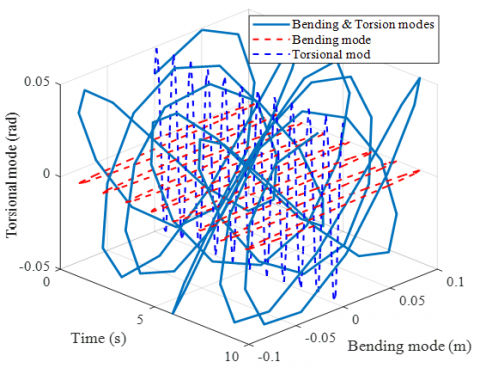
The 3D plot displays as shown in Figure 6, the wing flutter dynamics by showing the bending (vertical mode) and torsional (twisting mode) simultaneously over time. The bending mode is represented along the Y-axis and varies with time, while the torsional mode is along the Z-axis, showing how the wing twists over time. As time progresses along the X-axis, the oscillations of both modes can be seen in their 3D relationship.
Figure 6. 3D flutter dynamics with different mode
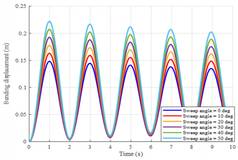
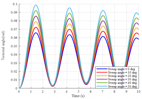
This graphical representation, shown in Figures 7 and 8, demonstrates that the sweep angle has a significant influence on the bending displacement and torsional rotation of the wing over time. Higher sweep angles (50°) reduce bending amplitude compared to lower sweep angles. This is because swept wings are typically more flexible. Similarly, increased sweep angles reduce torsional deformations. Higher sweep angles reduce the wing's torsional flexibility, and the geometry of the wing influences the couple interaction between bending and torsion.
Figure 7. Bending versus time with different sweep angles
Figure 8. Torsional versus time with different sweep angles
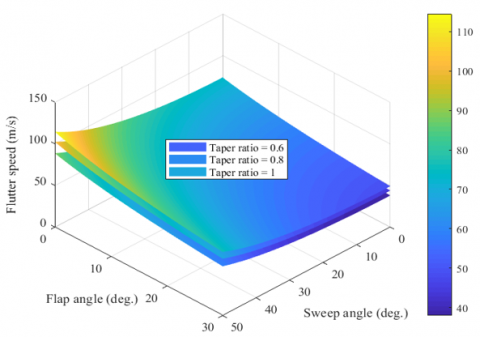
Figure 9 depicts a nonlinear comparison of flutter speed at various flap angles and sweep angles at taper ratios ranging from 0.6 to 1. These parameters are critical in determining the aeroelastic stability of an aircraft wing; each has an impact on the wing's aerodynamic and structural response.
Figure 9. 3D representation of an aircraft wing sweep angle, flap angle, and flutter speed
At minimal flap angles (approaching 0°) with negligible flap deflection, the wing exhibits enhanced aerodynamic stability, culminating in an increased flutter speed. The aerodynamic forces are more equitably distributed, and the torsional effects are constrained. Conversely, at elevated flap angles, when the flaps are significantly deflected, the aerodynamic forces on the wing change. Increased flap deflection leads to a rise in the pitching moment and induces higher torsional stresses on the wing, causing a reduction in flutter speed. This occurs because the deflection alters the aerodynamic damping and stiffness; both critical factors in flutter onset. Increasing the sweep angle initially from 0° to 10° reduces flutter speed, but then slightly increases with the sweep angle; the initial reduction is due to an increase in effective aerodynamic load, which changes the pitching moment and structural dynamics. High sweep angles (50°) reduce structural interdependence between bending and torsion, leading to higher flutter speeds. In contrast, at low sweep angles, the wing induces more structural coupling between the bending and torsional modes; this increased coupling typically reduces flutter speed, especially at low sweep angles, where the wing is more prone to aeroelastic instabilities such as flutter. There is a critical sweep angle beyond which the aerodynamic damping effect takes precedence over the destabilizing aerodynamic forces. Wings with a high taper ratio are closer to rectangular. Higher taper ratio (close to 1), these wings are more aerodynamically uniform and structurally stiffer along the span. The distributed aerodynamic forces are more balanced, leading to higher flutter speeds. As the taper ratio decreases (0.6 or 0.8), the wing tip experiences more torsional flexibility, which reduces the overall stiffness of the wing. This allows for more torsional motion during bending, which reduces the flutter speed as a result of the weaker aerodynamic damping.
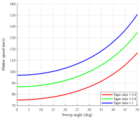
Figure 10 depicts a plot of flutter speed versus sweep angle for various taper ratios. As the sweep angle increases from 0 to 50, the flutter speed rises nonlinearly. This happens because sweep reduces the effective aerodynamic load, resulting in faster critical flutter speeds. A higher taper ratio results in faster flutter speeds, whereas a lower taper ratio causes slower flutter speeds. This is because increasing the taper ratio increases structural stiffness and reduces flutter susceptibility. A higher taper ratio and moderate sweep angle can improve flutter stability.
Figure 10. Flutter speed vs. sweep angle at varies tap ratio
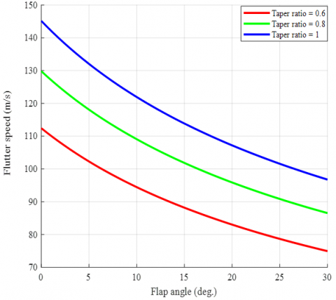
Figure 11 depicts the influence of the taper ratio on flutter speed. It showed that increasing the taper ratio reduces flutter speed. This was due to an increase in the structure's bending and torsional stiffness. It can be concluded that lift increases as the taper ratio.
Figure 11. Flutter speed vs. flap angle at varies tap ratio
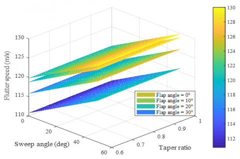
Figure 12 is a 3D plot that shows the relationship between flutter speed, flap angle, and taper ratio at various sweepback angles ranging from 0° to 50°. Flutter speed decreases as flap angle increases, implying that lower flap angles increase flutter speed, most likely due to changes in aerodynamic stiffness and damping effects. The flutter speed rises as the taper ratio approaches 1.0. A higher taper ratio indicates a less tapered wing, which may improve structural rigidity and delay flutter onset. The flutter speed decreases as the flap angle rises from 0° to 30° degrees; a higher flap angle may increase aerodynamic loads while decreasing the flutter margin. The plot shows proximate, nearly linear relationships between flap angle and flutter speed for all sweep angles. The slopes of the lines show that increasing the sweep angle decreases the sensitivity of flutter speed to changes in flap angle. Design optimization can focus on determining the best taper ratio and flap angle to achieve higher flutter speeds while maintaining aerodynamic efficiency.
Figure 12. Flutter speed with flap angle, taper ratio at various sweep angle
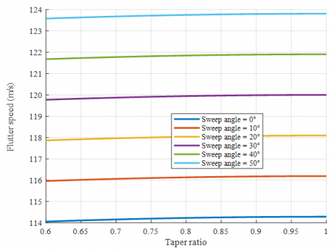
This graphical representation depicts the significant impact of the taper ratio on flutter speed across various sweep angles, as shown in Figure 13. Higher taper ratios (closer to one or less tapering) consistently result in higher flutter speed because they provide more structural stiffness and reduce the risk of aeroelastic instability. The optimal sweep angle for maximum flutter speed is extreme; flutter speed decreases with all taper ratios, especially for more tapered wings (lower taper ratios). These findings are critical for aircraft wings, emphasizing the importance of carefully balancing taper ratio and sweep angle to improve flutter stability while retaining aerodynamic efficiency. This indicates that wings with higher taper ratios have better flutter resistance.
Figure 13. Flutter speed vs. taper ratio at various sweep angle
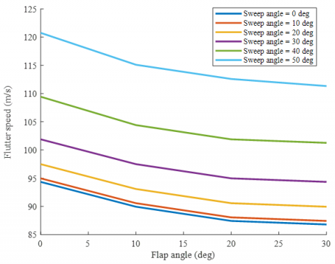
Figure 14 shows how the flap angle affects flutter speed at different sweep angles. The flutter speed decreases as the flap angle increases. The highest flutter speed is observed at a flap angle of zero degrees. Flutter speed gradually decreases as flap angles rise to 10, 20, and 30. This suggests that higher flap angles result in more unsteady aerodynamic loads, lowering flutter speed. Higher flap deflections improve flow effects, add aerodynamic loads that interact with structural dynamics, and reduce flutter speeds by increasing effective aerodynamic stiffness, making the wing more prone to flutter at lower speeds. Lower flap angles (0-10) increase aerodynamic stability and reduce disturbances, allowing for faster flutter speeds. Flutter speed decreases as the flap angle increases, and the curves shift downward, confirming the destabilizing effect of increased flap deflection.
Figure 14. Flutter speed vs. flap angle with various sweep angle
Figure 15 depicts the variation in flutter speed with sweep angle for various flap angles ranging from 0 to 30 degrees. As the sweep angle increases from 0° to 50° , the flutter speed increases monotonically, as shown by the curves. This is because sweep wings distribute aerodynamic forces differently, reducing effective dynamic pressure and increasing aerodynamic stability. Each curve represents a different flap deflection, and higher flap angles (30°) result in the slowest flutter speed. Flap deflection increases aerodynamic loading and, ultimately, the aerodynamic center, reducing flutter stability. The separation of curves demonstrates that flap deflection has a nonlinear effect on flutter characteristics. Deflecting the flap increases aerodynamic loading and changes the aeroelastic coupling, lowering flutter speed. Additional lift and moment modify the wing's structural response, making it more prone to fluttering. At higher flap angles, aerodynamic forces interact more strongly with elastic deformations, resulting in less aerodynamic damping. This accelerates the onset of flutter at slower speeds. Deploying flaps at high speeds reduces the flutter margin, which can lead to instability. Higher sweep angles slow the onset of flutter by lowering the component of aerodynamic forces normal to the wing. This results in a lower aerodynamic moment acting on the structure, increasing flutter stability, while the dynamic pressure component normal to the wing decreases, reducing the aerodynamic energy available to induce flutter. Swept wings have better flutter characteristics, making them a popular choice for high-speed aircraft.
Figure 15. Flutter speed with sweep angle, taper ratio at various flap
This graph depicts flutter speed as a function of sweep angle for various flap angles with a constant taper ratio of 0.8, as shown in Figure 16. The flap angles range from 0° to 30°, while the sweep angle ranges from 0° to 50°. The plot clearly shows how sweep angle and flap angle interact to influence the flutter speed of a wing with a fixed taper ratio. While moderate sweep angles and low flap deflections promote faster flutter speeds, extreme values of these parameters increase the risk of aeroelastic instability, lowering the critical flutter speed.
Figure 16. Flutter speed vs. sweep angle at varies flap angle
This graphical representation depicts the significant impact of the taper ratio on flutter speed across various flap angles, as shown in Figure 17. Higher taper ratios (closer to one or less tapering) consistently result in higher flutter speed because they provide greater structure stiffness and reduce the risk of aeroelastic instability. Flutter speed decreases for all taper ratios, particularly for more tapered wings (lower taper ratios). These findings are critical for aircraft wings, emphasizing the importance of carefully balancing taper ratio and sweep angle to improve flutter stability while retaining aerodynamic efficiency.
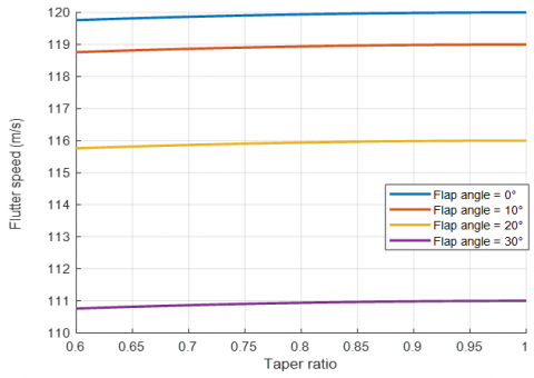
Figure 17. Flutter speed vs. taper ratio at varies flap angle
This research provides a detailed numerical analysis of the effects of sweep angle, flap angle, and taper ratio on flutter speed. Numerical analysis in MATLAB is used to forecast flutter speed across wing configurations, and the results are compared with previous theoretical research. The main findings are as follows:
These findings show how each geometric parameter affects flutter speed and highlight the importance of careful wing configuration optimization.
|
C |
mean aerodynamic chord, m |
|
$C_b$ |
structural damping in bending mode, Ns.m-1 |
|
$C_L$ |
lift force coefficient |
|
$C_m$ |
pitching moment coefficient |
|
$C_t$ |
structural damping in torsional mode, Ns.m-1 |
|
$K_b$ |
bending stiffness in bending mode, N.m-1 |
|
$K_t$ |
torsional stiffness in torsional mode, N.m-1 |
|
$I_t$ |
torsional inertia, kg.m3 |
|
L |
aerodynamic lift force, N |
|
M |
aerodynamic pitching moment, N.m |
|
$M_b$ |
moment in bending mode, N.m |
|
$M_t$ |
moment in torsional mode, N.m |
|
V |
airspeed/s, m.s-1 |
|
S |
reference wing area, m2 |
|
w |
bending displacement, m |
|
Greek symbols |
|
|
$\theta$ |
torsional angle, deg |
|
$\rho$ |
density of air, kg.m-3 |
|
$\alpha$ |
angle of attack, deg |
|
$\delta$ |
flap angle, deg |
|
$\lambda$ |
taper ratio |
|
$\Lambda$ |
sweep angle, deg |
|
$\omega$ |
angular speed, rad. s-1 |
|
Subscripts |
|
|
b |
bending mode |
|
t |
torsional mode |
|
aero |
aerodynamic forces |
[1] Bisplinghoff, R.L., Ashley, H., Halfman, R.L. (2013). Aeroelasticity. Courier Corporation. Dover Publications.
[2] Hussein, E., Azziz, H., Rashid, F. (2021). Aerodynamic study of slotted flap for NACA 24012 airfoil by dynamic mesh techniques and visualization flow. Journal of Thermal Engineering, 7(2): 230-239. https://doi.org/10.18186/thermal.871989
[3] Garrigues, E. (2018). A review of industrial aeroelasticity practices at Dassault aviation for military aircraft and business jets. Aerospace Lab, (14): 1-34. https://doi.org/10.12762/2018.AL14-09
[4] Raveh, D., Levy, Y., Karpel, M. (2000). Aircraft aeroelastic analysis and design using CFD-based unsteady loads. In 41st Structures, Structural Dynamics, and Materials Conference and Exhibit, Atlanta, GA, U.S.A., p. 1325. https://doi.org/10.2514/6.2000-1325
[5] Al-Zughaibi, A., Hussein, E.Q., Rashid, F.L. (2021). Numerical investigations of fluid structural interaction for aircraft wing flap structure using CFD technique. Journal of Mechanical Engineering Research and Developments, 44(3): 138-150.
[6] Abdelkefi, A., Vasconcellos, R., Nayfeh, A.H., Hajj, M.R. (2013). An analytical and experimental investigation into limit-cycle oscillations of an aeroelastic system. Nonlinear Dynamics, 71: 159-173. https://doi.org/10.1007/s11071-012-0648-z
[7] Wright, J.R., Cooper, J.E. (2008). Introduction to Aircraft Aeroelasticity and Loads. John Wiley & Sons. https://doi.org/10.1002/9781118700440
[8] Hodges, D.H., Pierce, G.A. (2011). Introduction to Structural Dynamics and Aeroelasticity. Cambridge University Press. https://doi.org/10.1017/CBO9780511997112
[9] Hodges, D.H., Patil, M.J., Chae, S. (2002). Effect of thrust on bending-torsion flutter of wings. Journal of Aircraft, 29(2): 371-376.
[10] Patil, M.J., Hodges, D.H. (2006). Flight dynamics of highly flexible flying wings. Journal of Aircraft, 43(6): 1790-1799. https://doi.org/10.2514/1.17640
[11] Anderson Jr, J.D. (1998). Aircraft Performance and Design. McGraw-Hill Education.
[12] Phillips, W.F. (2009). Mechanics of Flight. Wiley India Pvt. Ltd.
[13] Hall, K.C., Kielb, R.E., Thomas, J.P. (Eds.). (2006). Unsteady Aerodynamics, Aeroacoustics and Aeroelasticity of Turbomachines. Rotterdam, The Netherlands: Springer. https://doi.org/10.1007/1-4020-4605-7
[14] Dowell, E.H., Hodges, D.H. (2015). A Modern Course in Aeroelasticity. Springer. https://doi.org/10.1007/978-3-319-09453-3
[15] Rampurawala, A.M. (2005). Aeroelastic analysis of aircraft with control surfaces using CFD. Doctoral Dissertation, University of Glasgow.
[16] Clark, R., Cox, D., Gern, F. (2002). Active flutter suppression: State of the art and technology maturation needs. Journal of Aircraft, 39(4): 612-619. https://doi.org/10.2514/2.2989
[17] Gennaretti, M. (2022). Fundamentals of Aeroelasticity. Cham, Springer. https://doi.org/10.1007/978-3-031-53379-2
[18] Shubov, M.A. (2006). Flutter phenomenon in aeroelasticity and its mathematical analysis. Journal of Aerospace Engineering, 19(1): 1-12. https://doi.org/10.1061/(ASCE)0893-1321(2006)19:1(1)
[19] Lai, K.L., Tsai, H.M. (2007). Flutter simulation and prediction with CFD-based reduced-order model. In 45th AIAA Aerospace Sciences Meeting and Exhibit, Reno, Nevada. https://doi.org/10.2514/6.2007-731
[20] Drela, M. (2014). Flight Vehicle Aerodynamics. MIT Press.
[21] Molyneux, W.G. (1950). The flutter of swept and unswept wings with fixed-root conditions. In Reports and memoranda / Aeronautical Research Council, Vol. 2796, H.M.S.O.
[22] Etkin, B., Reid, L.D. (1996). Dynamics of Flight: Stability and Control. John Wiley & Sons.