Alaa Ali Salman Al-Taai![]()
© 2025 The author. This article is published by IIETA and is licensed under the CC BY 4.0 license (http://creativecommons.org/licenses/by/4.0/).
OPEN ACCESS
This paper summarizes the findings of a study aimed at enhancing the understanding of the fundamental performance of short circular columns constructed from steel tubes filled with concrete. This study presents a three-dimensional finite element model utilizing the ANSYS2023R1 software to analyze columns from steel tubes filled with concrete, assess performance enhancement, and examine the impact of critical parameter, including the concrete strength, the steel tube strength, the steel tube diameter-to-thickness percentage, and the slenderness percentage of the column. A 3D brick element eight-node SOLID 65 was used to depict the concrete, while a 3D solid element SOLID 185 was applied to represent the steel tube. The verification study indicates a strong correlation between the ANSYS simulations and the experimental test outcomes. The findings of the parametric analysis reveal that material and geometric characteristics greatly influence the axial strength of concrete filled steel tube (CFST) columns. Increasing the compressive strength of concrete and the yield strength of steel enhances the ultimate load. A rise in D/t percentage and L/D percentage leads to reductions in the ultimate load.
CFST, circular columns, confined concrete, finite element analysis, steel tube
Concrete filled inside steel tubes (CFST) column has gained importance in contemporary structures, including residential homes, high-rise buildings, and arch bridges [1, 2]. Concrete filled steel tubes are a cost-effective type of column because the concrete resists most of the axial load and is economically more viable than steel. The steel tube reduces construction time and costs by acting as a formwork for the concrete core [3-6]. The tube serves as both longitudinal and lateral reinforcement for the concrete core, minimizing the need for further reinforcement [7]. Additional cost reductions can be achieved because CFST columns span less areas on stories than bare steel and reinforced concrete equivalents [7, 8]. Concrete filled steel tubes columns are more active structural components than reinforced concrete or hollow steel columns. columns integrate the optimal attributes of both concrete and steel, exhibiting great strength, exceptional ductility, and considerable stiffness. Composite columns are utilized in constructions to withstand earthquake wave because of these characteristics as well as their high energy absorption capacity [9, 10].
Earlier tests on steel tubes filled with concrete for columns carried out by Gardner and Jacobson [11], Schneider [12], Han et al. [13], and Yu et al. [14] found that, in the scenario of pressure on the cross section of concrete, the steel tubes provide a confined influence on the core of concrete section when lateral deformations of the concrete core occurred. Besides, the contact the steel tube with the concrete core significantly affects both the structural behavior and the confinement effect, yet in the case of loading, the bond strength has no influence on the entire section. Yu et al. [14] conducted an Experimental examination of the performance of steel tube filled with concrete for columns employing self-compacting of concrete and conventional concrete, subjected to axial compressive loading until failure. The conclusion indicates that an enhancement in the compressive strength of two concrete types leads to a significant improvement in load capacity, whereas the impact of normal concrete (NC) and self-compacting concrete (SCC) with comparable strengths on the maximum load and failure mode of CFT column is minimal. Dundu [15] examined the behavior of CFST columns with varied diameters and lengths. The predominant failure mode of CFST columns was flexural buckling, exhibiting little evidence of local buckling because of the high slenderness percentage of the column. The specimens failed due to the fracturing the core of concrete and deformation of the steel tube.
The findings of prior investigations indicated that short CFST column exhibit exceptional dissipation for energy by way of ductility and load-bearing capability owing to enhanced confinement efficiency.
Despite experiments are essential for investigating CFST columns, they are notably costly and time-intensive, especially for studies including a broad spectrum of strengths and properties of materials. Thus, numerical analyses are crucial for offering further insights to prior tests and facilitating subsequent parametric analysis, thereby assisting in the prediction of structure behavior without numerical and empirical testing. The last few decades, several studies had examined CFST columns utilizing finite element (FE) techniques [16-20]. However, the majority of these finite element models have predominantly concentrated on CFST columns using normal strength concrete (NSC) or high strength concrete (HSC). In previous studies, Hu et al. [16] offered material model for CFT columns and validated them using ABAQUS. The study found that circular CFT columns show strong confinement effects, especially when the D/t ratio is small, while square CFT columns are less effective unless reinforced with ties, which enhance confinement when ties are closely spaced, and their diameter or quantity is relatively large.
Yu et al. [17] examined the behavior of different cross-sectional shapes of CFST columns filled by NSC subjected to axial force through a finite element analysis utilizing ABAQUS software. The tension behavior of steel tube filled with concrete (CFS) was examined by Han et al. [18]. The presence of core concrete in concrete-filled steel tubes enhances the tensile strength of the steel tube. A finite element model (FEM) was created to conduct mechanism analysis and parametric investigation. Bahrami et al. [19] investigated the behavior of stiffened concrete filled inside steel section utilizing finite element program LUSAS. The CFST stub columns are meticulously designed using specific arrangements, quantities, spacing, and bar stiffeners diameters, together varying steel thickness, concrete strength, and steel strength. The parameters influence the behavior of the columns. Tao et al. [20] developed an advanced finite element model that introduced a novel three-stage framework incorporating strain hardening with softening rules for concrete of confined, implemented in ABAQUS software alongside the calibration of essential material parameters within the damaged plasticity model of concrete. This novel finite element development can simulate steel tube filled by concrete below axial loading with various concrete strengths. Gupta and Singh [21] developed a numerical model to simulate steel tube filled with concrete column exposed to central loading utilizing the commercial finite element software ABAQUS. Gupta and Singh [21] examined changes in radial confinement pressure in the concrete core both circumferentially and vertically within the specimen. Haghinejad and Nematzadeh [22] conducted a nonlinear finite element study in ABAQUS program of circular steel-tube concrete columns below axially loaded utilizing novel confinement relationships for normal-strength concrete cores. Li et al. [23] examined the steel formwork concrete column utilizing a thin-walled form, building upon prior investigations of CFST buildings. Numerous aspects were examined, including concrete strength, reinforcing diameter, and width-to-thickness ratios, to rectify the shortcomings in the experimental design by numerical modeling. A survey of previous studies has revealed that is a shortage of discover directed towards the numerical analysis of circular CFST columns, particularly finite element (FE) models encompassing diverse concrete and steel strength.
To overcome the discovered study gap, the primary objective of this research is to examine the axial loaded behavior of circular steel tube filled with concrete (CFST) columns with a diverse array of material and geometric characteristics utilizing a novel finite element model in ANSYS2023R1-3D. A novel finite element model utilizing ANSYS2023R1-3D software has been created to simulate circular concrete-filled steel tubes columns with diverse material and geometric characteristics. The key point in this study is not merely the use of ANSYS 2023R1, but rather the effective utilization of its advanced capabilities to enhance the performance of the numerical model compared to previous studies. The software provided precise control over mesh generation, with accurate distribution along the circular cross-section of the column, which improved the stress and strain distribution and helped reduce convergence issues. Additionally, the solution algorithms in ANSYS 2023R1 demonstrated outstanding performance in nonlinear stages, particularly after the peak load, which is a phase that often presents challenges in other software such as ABAQUS and LUSAS. Accordingly, the developed model in this study offers a more accurate and reliable numerical representation of the axial behavior of circular CFST column.
Numerical methods, including finite element and finite difference techniques, have been employed more realistically to get approximate solutions to complex problems [24]. This study utilized the ANSYS computer program (version 2023R1) to model and analyze the specimens, demonstrating the similarity between prior experimental work and numerical analysis. The outcomes compare with experimental findings, involving the ultimate load, and ultimate deflection.
2.1 Used element types
2.1.1 SOLID 65
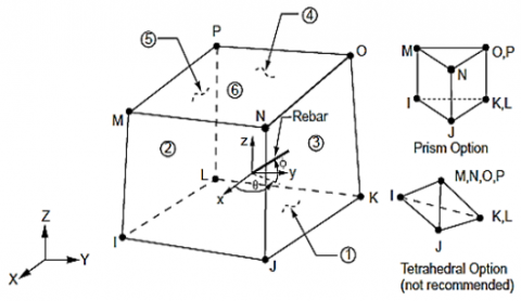
The SOLID 65 employed to model concrete inside ANSYS program. Each element comprises by eight nodes, each possessing three degrees of freedom for x-axis, y-axis, and z-axis translation. The element exhibits cracking potential perpendicular ways subject to tension and possesses the ability to fracture subject to compressive and plastic deformation. Figure 1 illustrates a depiction of SOLID 65. The cracking is represented using the smeared crack method. The multi-linear an isotropic slope depicted the established Uniaxial in stress-strain curve for the concrete compressive characteristics [25].
Figure 1. SOLID 65 element geometry [26]
SOLID 65 is used to model concrete because it can simulate cracking under tension and crushing under compression, which are not supported by most other elements in ANSYS. This element allows for accurate nonlinear analysis of concrete behavior, making it the optimal choice for realistically modeling concrete performance under various loads.
2.1.2 SOLID 185
The SOLID 185 components were employed to simulate the steel tube. The placement of nodes for element was analogous to those of element SOLID 65, as observed in Figure 1 [26]. The thickness of the elements used to represent the steel plate is equivalent to the thickness of the tube.
SOLID 185 is used because it accurately represents the elastic-plastic behavior of steel and effectively captures the local stress distribution. It is considered the optimal choice for modeling the metal, ensuring an integrated interaction between the nonlinear properties of each material, which reflects the limitation influence provided by the concrete on the steel tube.
2.1.3 Contact case between concrete and steel plate
This study investigates the contact between concrete core and the surrounding steel tube has been represented as a bonded contact. This assumption was made based on composite behavior of steel tube filled with concrete for column, where the concrete and steel tube are assumed to work together under load, enhancing the structural strength and stability.
In the ANSYS model, no contact elements are used between the surface of SOLID 65 (representing concrete) and SOLID 185 (representing the steel tube). Instead, a bonded interaction is assumed, meaning that the surfaces between infilled concrete and surrounding steel tube behave as if they were permanently bonded, with no sliding or separation occurring.
2.2 Boundary conditions
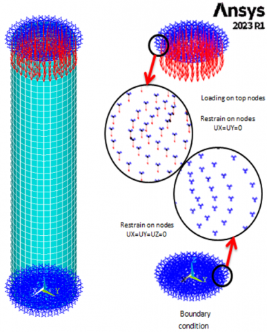
Boundary conditions were applied to simulate the behavior of the columns under experimental tests. At the column base, a support state was implemented by limiting all translational freedom degrees, ensuring that displacements in all directions were fully constrained, effectively replicating a rigid support. At the top, the load was applied uniformly over the entire surface of the model. In this region, displacements in the two horizontal directions were restrained, while vertical movement in the load direction was permitted, as shown in Figure 2. These conditions are essential for ensuring the model's stability and accurately representing the column's behavior under various loadings.
Figure 2. Boundary conditions of CFST columns by ANSYS2023R1
2.3 Meshing and convergence criteria
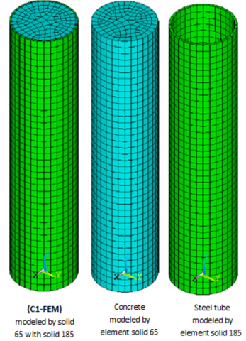
The model was discretized using a three-dimensional mesh suitable for analyzing stresses and deformations within the column. The type of elements was chosen based on their capability to accurately represent the stress distribution (SOLID 185 and SOLID 65 elements), as shown in Figure 3, and a mesh study was directed to ensure that the results’ accuracy was not significantly affected by changes in element size.
Regarding convergence criteria, strict standards were adopted based on the relative differences in energy and displacement between iterative solutions. Convergence was considered achieved when the changes in results were less than 5% between successive iterations. This approach helps ensure the stability of the results and reduces potential numerical errors.
Figure 3. Mesh and used element types by ANSYS2023R1
2.4 Material modeling
The material properties in the column model were accurately defined to replicate their actual behavior under loading conditions. For concrete, the SOLID 65 A concrete material model based on the Willam–Warnke failure criterion was adopted to represent the concrete under tension and compression. Key parameters such as compressive and tensile strengths, along with parameters that aid in numerical stability, were specified, along with critical strain values. The model is established on theory of concrete failure, which accounts for nonlinear effects under various stress states.
For steel, the SOLID 185 model was used, an appropriate plasticity-based hardening model, such as isotropic hardening, was used to simulate material behavior after yielding. The von Mises yield criterion was applied to define the yield point, and the hardening characteristics were calibrated based on experimental data to ensure accurate stress-strain behavior. This detailed material modeling contributes to enhancing accuracy of the model in predicting the column’s response under various loads.
3.1 Experimental results
Previous experimental investigations on circular columns composed of steel tube filled with concrete by Lachemi et al. [27], and Ali et al. [28] were utilized to validation the FEM established in this research. Table 1 explains the properties of the geometrical and material for the tested specimens.
Table 1. Data from previous experimental work on circular CFST short columns
|
Specimens According to References |
Dimensions |
Material Properties |
Experimental Ultimate Load (kN) |
Tested By |
|||||
|
(D) (mm) |
(t) (mm) |
(L) (mm) |
(D/t) |
(L/D) |
(F'c) (MPa) |
(Fy) (MPa) |
|||
|
CI-NC-4.4 |
114 |
4.4 |
500 |
26 |
4.4 |
52 |
300 |
1237 |
Lachemi et al. [27] |
|
CI-NC-8.8 |
114 |
4.4 |
1000 |
26 |
8.8 |
52 |
300 |
1087 |
|
|
S1 |
160 |
2.8 |
400 |
57 |
2.5 |
30 |
368 |
1370 |
Ali et al. [28] |
|
M1 |
160 |
2.8 |
1000 |
57 |
6.25 |
30 |
368 |
1300 |
|
The specimens utilized in the experiments performed by Lachemi et al. [27] had an outer diameter of 114 mm and two lengths of 1000 mm and 500 mm. The specimens CI-NC-4.4 and CI-NC-8.8 consisted of concrete fill inside steel tube columns 4.4 mm thickness and concrete strengths of 52 MPa. The experiments were performed on concrete-fill inside steel tube column exposed toward compression between ends. The yield stress of steel tube was 300 MPa, for thickness of 4.4mm. Ratios of the length to diameter for specimens CI-NC-4.4 and CI-NC-8.8 were 4.4 and 8.8, respectively.
The circular concrete fill inside steel tube columns tested by Ali et al. [28] featured thickness of steel tube plate of 2.8 mm with nominal diameters of 160 mm. Specimen S1 has column length of 400 mm and ratio of column length to diameter of 2.5. Specimen M1 has column length of 1000 mm and column length to diameter percentage of 6.25. The concrete strength was 30 MPa. The yield stress of the steel tube was 368 MPa.
3.2 Comparison of finite element analysis with experimental data
A comparison was made among the investigational findings and the F.E. outcomes to validate the F.M. representation. The ultimate loads acquired from the previous experimental findings (PExp.) [27, 28] and current analysis of finite element (PFEM) with the load–axial shortening curves have undergone examination.
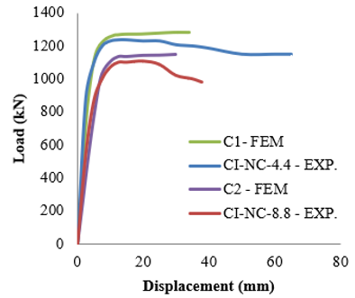
Table 2 presents the ultimate loads of concrete fill inside steel tubes columns, derived from both experimental and numerical methods utilizing the finite element representation. There is a notable agreement between the two groups of the majority results of the columns. The differentiation between numerical results and experimental results was expressed as the percentage of (P(FEM)-P(Test((/P(FEM), where P(FEM) represents the ultimate load obtained from numerical results and P(Test( refers to the ultimate load obtained from experimental results. The observed differentiation for specimens (C1- FEM), (C2- FEM), (C3- FEM), and (C4- FEM) were 3.7%, 5.1%, 4.2%, and 4.5%, respectively. The ratio of P(Test(/P(FEM) for these specimens was 0.963, 0.949, 0.958, and 0.955, respectively. The mean P(Test(/P(FEM) ratio was 0.956, as shown in Table 2. The specimen (C1-FEM) is the most convergence between the geometric analysis and the investigational analysis, showing a strong correlation between the geometric and investigational results compared to the other specimens. The differentiation is primarily due to the lack of convergence between the theoretical analysis and the practical testing. This discrepancy can arise from various factors, such as variations in material properties, differences in boundary conditions, or limitations in the accuracy of the experimental setup, which may not perfectly replicate the idealized assumptions used in the theoretical model. Figure 3 illustrates the representation of the specimen (C1-FEM) within ANSYS2023R1 software environment.
Table 2. The ultimate loads of previous experimental results and FEM results of CFST short columns
|
Name of Specimens According to FEM Analysis |
Name of Specimens According to Reference's |
PExp. |
PFEM |
PExp./PFEM |
|
C1- FEM |
CI-NC-4.4 |
1237 |
1285 |
0.963 |
|
C2- FEM |
CI-NC-8.8 |
1087 |
1146 |
0.949 |
|
C3- FEM |
S1 |
1370 |
1430 |
0.958 |
|
C4- FEM |
M1 |
1300 |
1360 |
0.955 |
|
mean |
|
|
|
0.956 |
|
COV |
|
|
|
0.005 |
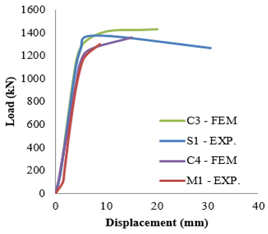
Previous experimental tests of the load-axial displacement curves were in comparison with the numerical analysis, demonstrating a strong correlation. Figures 4 and 5 illustrate the load-axial displacement behavior of concrete fill inside steel tubes columns. The specimen (C1-FEM) exhibited concrete cube strength of (52 MPa), (114 mm) diameter, and steel tubes thickness (4.4 mm), with (300 MPa) tensile strength. There is a strong correlation between tests and a numerical load- axial displacement behavior. The P(Test)/P(FEM) ratio was 0.963, as indicated in Table 2.
Figure 4. The load-axial shortening curves between previous experimental work [27] and FEM analysis
Figure 5. The load-axial shortening curves between previous experimental work [28] and FEM analysis
A parametric study is conducted on specimen (C1-FEM) using the developed finite element model Figure 3, which has been validated against prior test results, to assess the influence of steel tube strength, concrete strength, percentage of steel tube diameter to thickness, and slenderness percentage of the columns. The parametric study investigated 22 columns, with their dimensions and material attributes detailed in Table 3.
Table 3. The geometrical and material properties in parametric study of the columns
|
Study |
Parameter |
Parametric Specimens |
Geometrical Properties |
Material Properties (MPa) |
PFEM |
|||||
|
Dimension (mm) |
Ratio |
|||||||||
|
L |
D |
t |
D/t |
L/d |
F'c |
Fy |
||||
|
Parametric |
Concrete Strength |
1 |
500 |
114 |
4.4 |
26 |
4.4 |
75 |
300 |
1338.75 |
|
2 |
500 |
114 |
4.4 |
26 |
4.4 |
100 |
300 |
1477.9 |
||
|
3 |
500 |
114 |
4.4 |
26 |
4.4 |
120 |
300 |
1657.5 |
||
|
4 |
500 |
114 |
4.4 |
26 |
4.4 |
150 |
300 |
1874.25 |
||
|
5 |
500 |
114 |
4.4 |
26 |
4.4 |
200 |
300 |
2185.3 |
||
|
Steel Strength |
6 |
500 |
114 |
4.4 |
26 |
4.4 |
52 |
241 |
909.3 |
|
|
7 |
500 |
114 |
4.4 |
26 |
4.4 |
52 |
248 |
974.3 |
||
|
8 |
500 |
114 |
4.4 |
26 |
4.4 |
52 |
289 |
1234.1 |
||
|
9 |
500 |
114 |
4.4 |
26 |
4.4 |
52 |
317 |
1493.9 |
||
|
10 |
500 |
114 |
4.4 |
26 |
4.4 |
52 |
344 |
1623.8 |
||
|
11 |
500 |
114 |
4.4 |
26 |
4.4 |
52 |
390 |
1818.6 |
||
|
12 |
500 |
114 |
4.4 |
26 |
4.4 |
52 |
440 |
2143.4 |
||
|
13 |
500 |
114 |
4.4 |
26 |
4.4 |
52 |
490 |
2338.2 |
||
|
Diameter to Thickness ratio |
14 |
500 |
114 |
3.8 |
30 |
4.4 |
52 |
300 |
1277.9 |
|
|
15 |
500 |
114 |
2.85 |
40 |
4.4 |
52 |
300 |
1070 |
||
|
16 |
500 |
114 |
2.3 |
50 |
4.4 |
52 |
300 |
783.2 |
||
|
17 |
500 |
114 |
1.9 |
60 |
4.4 |
52 |
300 |
488.2 |
||
|
Length to Diameter Ratio |
18 |
342 |
114 |
4.4 |
26 |
3 |
52 |
300 |
1387.7 |
|
|
19 |
684 |
114 |
4.4 |
26 |
6 |
52 |
300 |
1257.7 |
||
|
20 |
1026 |
114 |
4.4 |
26 |
9 |
52 |
300 |
1182.4 |
||
|
21 |
1368 |
114 |
4.4 |
26 |
12 |
52 |
300 |
1009.1 |
||
|
22 |
1710 |
114 |
4.4 |
26 |
15 |
52 |
300 |
927 |
||
|
Verification |
C1-FEM |
500 |
114 |
4.4 |
26 |
4.4 |
52 |
300 |
1285 |
|
4.1 Grade of concrete
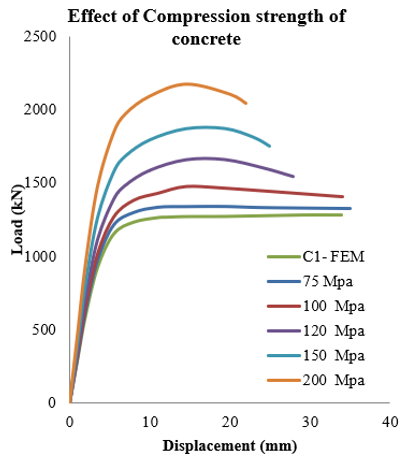
This modeling involves five circular short columns specimens to examine an impact of concrete difference on the compression behavior. Figure 6 illustrates load-axial shortening curves, whereas Figure 7 shows the impact of concrete grade variation on ultimate load of CFST column. Stiffness grows with the enhancement of concrete strength; yet, columns suffer to failure through the concrete crushing, demonstrating brittle behavior when utilizing high-strength concrete (f'c < 50 MPa and > 100 MPa) and ultra-high-performance concrete (f'c < 100 MPa and > 800 MPa). Nonetheless, it is a truth that an augmentation in concrete core strength substantially improves the column strengths. The load-bearing capability of columns increases with high value of concrete strength. Increasing a strength beginning 52 MPa toward (200 MPa) raises the ultimate load-bearing capacity by 70.06%.
Figure 6. Effect of concrete strength on load-axial shortening curves of CFST columns
Figure 7. Effect of concrete strength on the ultimate load
4.2 Grade of steel
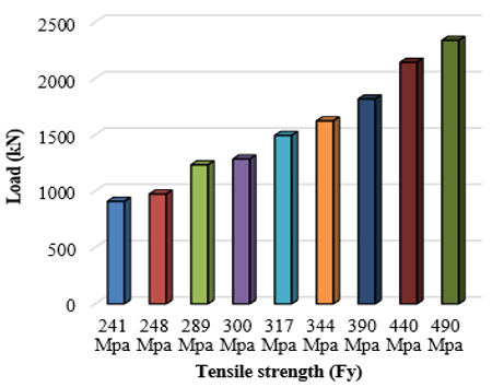
Eight circular short columns specimens are analyzed to examine an impact of steel grade variation on axial compression performance. Figure 8 depicts the influence of yield strength variation on the ultimate load of CFST columns, whereas Figure 9 illustrates the load-axial shortening curves. The strength of a CFST columns is influenced by a variance in steel grade. As to ANSI/AISC360 and ASTM standards, the yield strength of steel differs by type: Pipe A53 Gr.B has a yield strength of 241 MPa, A501 has 248 MPa, A501 Gr.B has 289 MPa, A501 Gr.C has 317 MPa, and A618 has 344 MPa. According to EN and CAN/CSA regulations, the yield strength of steel ranges from 235 MPa to 490 MPa. Upon examining the yield strength data, the findings indicate that the ultimate load-bearing capability escalates with rises in the steel yield strengths. The load ultimate rises by 81.96% once the yield strengths are elevated beginning (300 MPa) toward (490 MPa).
Figure 8. Effect of yield strengths on the ultimate load
Figure 9. Effect of yield strength of steel tube on load-axial shortening curves of columns
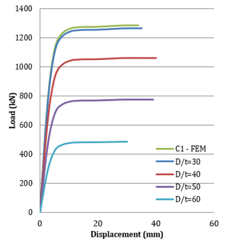
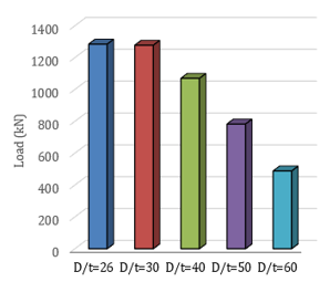
4.3 Ratio of diameter to thickness
This analysis examines four circular short columns specimens to assess thickness variation effective on column behavior. Figure 10 illustrates the load-axial shortening curves, while Figure 11 depicts the influence of percentage of diameter to thickness of columns on the ultimate load. The ratio of D/t in this research varies from (25) to (60). A growth in the D/t percentage may occur due to both a raise by diameter or a reduction by thickness. Consequently, Analysis is conducted by maintaining a fixed diameter during a change of steel tube thickness. The increase in D/t percentage when upward the steel tube thickness for a certain steel tube diameter indicates an enhancement in the steel section, resulting in a larger sectional capacity. The outcomes demonstrate that the maximum load of columns rises when the D/t ratio decreases. CFST columns' capacities can be improved by augmenting the tube thickness. Augmenting the D/t ratio beginning 25 toward 70 leads to a 62% decrease in ultimate load of the column.
Figure 10. Effect of diameter to thickness ratio of steel tube on load-axial shortening curves of CFST columns
Figure 11. Effect of D/t ratio of steel tube on the ultimate load
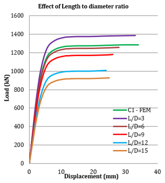
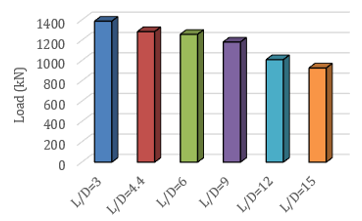
4.4 Ratio of length to diameter (slenderness ratio)
This study examines five circular short column specimens to analyze the effective variation in slenderness ratio (L/D) on column performance. Figure 12 illustrates the load-axial shortening curves, while Figure 13 depicts the impact of the length-to-diameter percentage on the ultimate load of CFST columns. The L/D ratio in this study varies from 3 to 15. The slenderness ratio of 15 defines the boundary between short and long columns. An increase in L/D ratio may result from either an increase in length or a decrease in diameter of the section. Consequently, the analysis is conducted by maintaining a fixed diameter while changing the length. The findings indicate that the ultimate load of CFST column diminishes as the length-to-diameter percentage of the column increases. Increasing the L/D percentage beginning 4.4 to 15, outcomes in a 28% drop in ultimate load of column.
Figure 12. Effect of length to diameter ratio of steel tube on load-axial shortening curves of CFST columns
Figure 13. Effect of L/D ratio of steel tube on the ultimate load
This study introduces a finite element representation for analyzing high-strength and ultra-high-performance concrete-filled steel tube circular short columns subjected to uniform axial loads, as well as examining the effects of steel strength and D/t ratio as related to L/D ratio. The parametric analysis yields the following significant conclusions:
[1] Wang, F.Q., Liu, F.Q., Yang, H., Peng, K., Wang, X.Z. (2024). Experimental and numerical investigations of post-fire behaviour of circular steel tube confined steel-reinforced concrete columns under eccentric loading. Journal of Building Engineering, 95: 110345. https://doi.org/10.1016/j.jobe.2024.110345
[2] Tao, Z., Han, L.H., Wang, D.Y. (2008). Strength and ductility of stiffened thin-walled hollow steel structural stub columns filled with concrete. Thin-Walled Structures, 46(10): 1113-1128. https://doi.org/10.1016/j.tws.2008.01.007
[3] Ferhoune, N. (2014). Experimental behaviour of cold-formed steel welded tube filled with concrete made of crushed crystallized slag subjected to eccentric load. Thin-Walled Structures, 80: 159-166. https://doi.org/10.1016/j.tws.2014.02.014
[4] Giakoumelis, G., Lam, D. (2004). Axial capacity of circular concrete-filled tube columns. Journal of Constructional Steel Research, 60(7): 1049-1068. https://doi.org/10.1016/j.jcsr.2003.10.001
[5] Lai, M.H., Ho, J.C.M. (2014). Confinement effect of ring-confined concrete-filled-steel-tube columns under uni-axial load. Engineering Structures, 67: 123-141. https://doi.org/10.1016/j.engstruct.2014.02.013
[6] Yang, Z.Y., Qiao, Q.Y., Cao, W.L., Gao, X.P. (2022). Axial compressive behavior of square steel tube confined rubberized concrete stub columns. Journal of Building Engineering, 52: 104371. https://doi.org/10.1016/j.jobe.2022.104371
[7] Chitawadagi, M.V., Narasimhan, M.C., Kulkarni, S.M. (2010). Axial strength of circular concrete-filled steel tube columns—DOE approach. Journal of Constructional Steel Research, 66(10): 1248-1260. https://doi.org/10.1016/j.jcsr.2010.04.006
[8] Ekmekyapar, T., Al-Eliwi, B.J. (2016). Experimental behaviour of circular concrete filled steel tube columns and design specifications. Thin-Walled Structures, 105: 220-230. https://doi.org/10.1016/j.tws.2016.04.004
[9] Lee, E.T., Yun, B.H., Shim, H.J., Chang, K.H., Lee, G.C. (2009). Torsional behavior of concrete-filled circular steel tube columns. Journal of Structural Engineering, 135(10): 1250-1258. https://doi.org/10.1061/(ASCE)0733-9445(2009)135:10(1250)
[10] Peng, C., Syamsunur, D., Jassam, T.M., Zhang, Z. (2025). Research on the confinement mechanism and calculation method of axial load-bearing capacity of steel-reinforced concrete-filled square steel tubular columns. Discover Applied Sciences, 7(1): 82. https://doi.org/10.1007/s42452-025-06473-9
[11] Gardner, N.J., Jacobson, E.R. (1967). Structural behavior of concrete filled steel tubes. Journal Proceedings, 64(7): 404-413. https://doi.org/10.14359/7575
[12] Schneider, S.P. (1998). Axially loaded concrete-filled steel tubes. Journal of structural Engineering, 124(10): 1125-1138. https://doi.org/10.1061/(ASCE)0733-9445(1998)124:10(1125)
[13] Han, L.H., Yao, G.H., Chen, Z.B., Yu, Q. (2005). Experimental behaviours of steel tube confined concrete (STCC) columns. Steel and Composite Structures, An International Journal, 5(6): 459-484. https://doi.org/10.12989/scs.2005.5.6.459
[14] Yu, Z.W., Ding, F.X., Cai, C.S. (2007). Experimental behavior of circular concrete-filled steel tube stub columns. Journal of Constructional Steel Research, 63(2): 165-174. https://doi.org/10.1016/j.jcsr.2006.03.009
[15] Dundu, M. (2012). Compressive strength of circular concrete filled steel tube columns. Thin-Walled Structures, 56: 62-70. https://doi.org/10.1016/j.tws.2012.03.008
[16] Hu, H.T., Huang, C.S., Wu, M.H., Wu, Y.M. (2003). Nonlinear analysis of axially loaded concrete-filled tube columns with confinement effect. Journal of Structural Engineering, 129(10): 1322-1329. https://doi.org/10.1061/(ASCE)0733-9445(2003)129:10(1322)
[17] Yu, Q., Tao, Z., Liu, W., Chen, Z.B. (2010). Analysis and calculations of steel tube confined concrete (STCC) stub columns. Journal of Constructional Steel Research, 66(1): 53-64. https://doi.org/10.1016/j.jcsr.2009.08.003
[18] Han, L.H., He, S.H., Liao, F.Y. (2011). Performance and calculations of concrete filled steel tubes (CFST) under axial tension. Journal of Constructional Steel Research, 67(11): 1699-1709. https://doi.org/10.1016/j.jcsr.2011.04.005
[19] Bahrami, A., Badaruzzaman, W.H.W., Osman, S.A. (2013). Behaviour of stiffened concrete-filled steel composite (CFSC) stub columns. Latin American Journal of Solids and Structures, 10: 409-440. https://doi.org/10.1590/S1679-78252013000200009
[20] Tao, Z., Wang, Z.B., Yu, Q. (2013). Finite element modelling of concrete-filled steel stub columns under axial compression. Journal of Constructional Steel Research, 89: 121-131. https://doi.org/10.1016/j.jcsr.2013.07.001
[21] Gupta, P.K., Singh, H. (2014). Numerical study of confinement in short concrete filled steel tube columns. Latin American Journal of Solids and Structures, 11: 1445-1462. https://doi.org/10.1590/S1679-78252014000800010
[22] Haghinejada, A., Nematzadeh, M. (2016). Three-dimensional finite element analysis of compressive behavior of circular steel tube-confined concrete stub columns by new confinement relationships. Latin American Journal of Solids and Structures, 13(5): 916-944. https://doi.org/10.1590/1679-78252631
[23] Li, S.Q., Wang, J., Wei, J.B., Shi, T.Y., Li, Y.D. (2025). Finite-element modeling of concrete-filled steel tubular columns under axial compression. Journal of Architectural Engineering, 31(1): 04024047. https://doi.org/10.1061/JAEIED.AEENG-1911
[24] Al-Taai, A.A.S., Hassan, S.A., Hussein, L.F. (2018). Finite element analysis of corner strengthening of CFRP-confined concrete column. IOP Conference Series: Materials Science and Engineering, Istanbul, Turkey, 454(1): 012088. https://doi.org/10.1088/1757-899X/454/1/012088
[25] Desayi, P., Krishnan, S. (1964). Equation for the stress-strain curve of concrete. Journal Proceedings, 61(3): 345-350. https://doi.org/10.14359/7785
[26] ANSYS, Inc. (2023). Top 5 Features in Ansys Mechanical 2023 R1. https://www.ansys.com/blog/mechanical-2023-r1.
[27] Lachemi, M., Hossain, K.M., Lambros, V.B. (2006). Axial load behavior of self-consolidating concrete-filled steel tube columns in construction and service stages. ACI Structural Journal, 103(1): 38-47. https://doi.org/10.14359/15084
[28] Ali, A.A., Abdul-Sahib, W.S., Sadik, S.N. (2013). Experimental behavior of circular steel tubular columns filled with self-compacting concrete under concentric load. Engineering and Technology Journal, 31(14): 2760-2772. https://doi.org/10.30684/etj.2013.83259