Waffa M. Abbod | Akram H. Abed*![]() | Alaa Siham Hamid
| Alaa Siham Hamid![]()
© 2025 The authors. This article is published by IIETA and is licensed under the CC BY 4.0 license (http://creativecommons.org/licenses/by/4.0/).
OPEN ACCESS
Numerous studies into new power plant layouts have been inspired by the search for sustainable and efficient energy generation. The unique hybrid power production system that combines the Brayton cycle with several Organic Rankine Cycles (ORCs) is investigated in depth numerically in this paper. To improve overall system performance and environmental sustainability, the suggested configuration makes use of the synergy between gas and organic Rankine cycles. This power plant's main component is a gas turbine that uses the Brayton cycle to turn compressed air at high temperatures into mechanical work. Before entering the ORC subsystems, the gas turbine's exhaust gases are sent through a recuperation for waste heat recovery. By efficiently utilizing waste heat at various temperatures, the numerous ORCs use various organic working fluids with variable boiling points to enhance thermal efficiency. This series of ORCs guarantees effective heat recovery and significantly lowers energy waste. The study shows that higher entry temperatures reduce system efficiency, with the worst case being 51 degrees Celsius, resulting in 38.5% energy efficiency. The best entry temperature is 15 degrees Celsius, achieving 40.01% efficiency and 37.1% exergy. The study reveals that increasing compressor efficiency leads to higher total system efficiency, with the best efficiency at 90%. The temperature of the exhaust also affects efficiency, with higher temperatures reducing efficiency and exergy.
Brayton cycle, ORCs, hybrid power system, waste heat, thermal efficiency
The urgent demand for sustainability and better energy efficiency is driving a major transition in the world's energy landscape. Power generation technologies are constantly changing in this setting to meet the expanding demand for electricity while reducing environmental effects. The use of diverse thermodynamic cycles is one viable route in the search for cleaner and more effective power generation. A detailed review of a combined cycle power plant (CCPP) using thermodynamic analyses of each system component is provided by Ibrahim et al. [1]. They claimed that the condenser suffered the most energy losses, with the combustion chamber destroying the most energy. Also, they found that the exergy analysis is an effective technique for evaluating the CCPP's performance, as it can help identify more efficient configurations that reduce fuel requirements and air pollution emissions. Kotowicz and Brzęczek [2] evaluated various gas turbine (GT) upgrades in a modern combined-cycle power plant to improve electrical efficiency. They examined sequential combustion, closed-air cooling, closed steam cooling, and open-air air cooling without and with cooling air coolers. They also highlighted the impact of higher permitted metal blade temperature on gas turbine efficiency and the power plant. They found that the net electric efficiency can be increased up to 0.63-0.65. Sabouhi et al. [3] presented a reliability model that focuses on dependability modelling for CCPP to make techno-economical decisions on equipment maintenance. Reliability models are created for gas turbine power plants (GTPP) and steam turbine power plants (STPP), identifying key components with the greatest influence on system reliability and availability targets. This helps in choosing effective maintenance plans, allowing for efficient planning and techno-economic resource allocation. Kotowicz et al. [4] discussed methods to enhance efficiency in CCPP by modifying gas turbine features and utilizing heat from the cooling air. They demonstrated that enhancing the turbine's features is the only way to increase efficiency without using heat. Performance improvements were proposed by Mansouri et al. [5], including increasing the cycle peak temperature ratio and peak compression ratio. The CCGT power plant performance model, created using the MATLAB program, showed a high overall thermal efficiency of 58% and increased cycle peak temperature and compression ratios. Ersayin and Ozgener [6] analyzed an operating power plant to determine energy and exergy efficiency using real-world data and thermodynamics. The CCPP energy efficiency is 56% and 50.04%, respectively, with the ignition chamber having the maximum exergy destruction rate. Tică et al. [7] demonstrated an approach for converting a CCPP physical model into an optimization-oriented model, enhancing start-up performance. The process involves continuous approximations of the Heaviside function, demonstrating model consistency and suitability for optimization and control. Liang et al. [8] investigated the impact of water mass flow rates and inlet temperatures on the COP, capacity of cooling and heating, and water outlet temperatures in evaporator and gas cooler systems. Tran’s critical CO2 heat pumps are used for cooling and heating simultaneously. Results show that water mass flow rate and inlet temperature significantly influence system performance, while a gas cooler's inlet temperature has a greater effect on performance and outlet temperatures. Both traditional and cutting-edge energetic techniques are provided by Petrakopoulou et al. [9] to examine a CCPP. Most energy destruction is inevitable, except for the high-pressure steam turbine and gas turbine expander. Internal technological constraints limit unavoidable components, and endogenous exergy degradation indicates component interactions are not a major cause of thermodynamic inefficiencies.
Another theoretical investigation to analyzes the thermodynamics of combined cycle gas turbines, considering various configurations and their impact on performance was presented by Ibrahim et al. [10]. The study uses MATLAB software to simulate gas turbine design, finding that regenerative gas turbines have higher efficiency at lower compression ratios. Also, they suggested that higher overall efficiency can be achieved with regenerative additions to the topping cycle, highlighting the significant influence of ambient temperature and compression ratios on combined cycle performance. Precise gas turbine models have been developed by Shalan et al. [11] to understand, simulate, and analyze the behavior of gas turbine-based facilities to address power system issues. By comparing responses of various dynamic models, three were fully simulated using Matlab/Simulink. The results showed similar efficiency and precision to those in relevant literature, indicating the efficiency and precision of the frequency-dependent and comprehensive models of gas turbines in CCPP. Chacartegui et al. [12] investigated the bottoming cycle for medium- and large-scale combined cycle power plants using low-temperature. The study considers organic fluids R113, R245, isobutene, toluene, cyclohexane, and is pentane. Competitive performances with high global efficiencies have been achieved for toluene and cyclohexane ORC combined cycles. Alobaid et al. [13] discussed the use of static and dynamic simulation models to improve the start-up of a combined cycle power plant. The simulation accurately estimates the dynamic behavior of the real HRSG and can forecast operational operations. Their finding concluded that can shorten start-up time and control lifetime consumption of severely stressed components. Polyzakis et al. [14] provided guidelines for optimizing a CCPP by contrasting four various gas turbine cycles: the simple cycle, the reheated cycle, the intercooled cycle, and the intercooled and reheated cycle. With 200 MW coming from the gas turbine and 100 MW from the steam turbine, the projected CCPP will yield 300 MW of electricity. The study investigated each alternative cycle for a combined power plant operating at base load, focusing on efficiency, installation and operating costs, maintainability, and dependability. Also, the study explored various schemes, including the simple cycle, intercooled cycle, reheated cycle, and intercooled and reheated cycle designs. Koch et al. [15] proposed an evolutionary approach to reduce the cost of the sophisticated CCPP product. The process variables and design configuration (process structure) are both optimized at the same time. The optimization algorithm may select from a variety of superstructure design options for the power plant, includes several gas turbine systems on the marketplace, up to three levels of pressure in the heat-recovery steam generator for generation of steam, steam reheating, supplementary firing, parallel design of heat exchangers in the gas path, and injection of steam in the gas turbine. The magnitude, location, and sources of the thermodynamic inefficiencies are determined by a thorough exergy study of selected intermediate solutions and the final ideal design. Cihan et al. [16], carried out an extensive energy and exergy analysis of a CCPP, focusing on energy and exergy fluxes and losses. They found that combustion chambers, gas turbines, and heat recovery steam generators (HRSG) account for over 85% of irreversible energy losses. To enhance system efficiency, beneficial and thermal recommendations were provided for these components. A technical and financial evaluation [17] concluded that the best design for Iran's first solar power plant is the Integrated Solar Combined Cycle System with 67 MW Solar Field (ISCCS-67). In its 30-year working life, the ISCCS-67 saves 59 million dollars in fuel costs and 2.4 million tons by CO2 emissions reduction. It also increases overall efficiency by 4% and steam turbine capacity by 50%. The LEC of ISCCS-67 is 10 and 33% cheaper than combined cycle and gas turbine at the same capacity factor.
This paper presents a numerical investigation of the viability and performance of an innovative idea that combines the Brayton cycle with several Organic Rankine Cycles (ORCs) in a single electric power plant. The ORC, a proven system for capturing low-temperature waste heat, and the conventional Brayton cycle, used in gas turbine power plants, represent two different methods of producing electricity. The ORCs thrive at extracting energy from lower-temperature heat sources, such as industrial operations or geothermal reservoirs, while the Brayton cycle excels at converting high-temperature pressured air into mechanical work. The synergies that can be tapped into to improve energy conversion efficiency and lower greenhouse gas emissions are what motivate the idea of integrating various cycles inside a single power plant. This hybrid power plant's main goal is to capture and use waste heat from the exhaust gases of the Brayton cycle by piping them into various ORC subsystems. The organic working fluid used by each ORC has a distinct boiling point, enabling effective heat recovery at various temperatures. This cascading strategy makes sure that a large amount of the heat that would otherwise be lost is transformed into electricity, improving the entire system's sustainability and efficiency [18].
The model talked about in this paper has been arranged for the natural gas consolidated cycle (NGCC) consistent state examination. It comprises of two fundamental parts, the initial segment is Brayton cycle, that consists of a gas turbine (GT), air blower (AC), combustion chamber (CC), and the subsequent section addresses the natural Rankine cycle, which comprises of a heat exchanger (HE), an organic rankine turbine (ORT), Condenser2 (CON2), Siphon (P) and heat recovery boiler (HRB) (see Figure 1). The working guideline of the installed framework can be summed up as follows. At the point when air enters an air compressor (AC), it is compacted to working tension and warmed. The air is then shipped to a controller place where it responds with gaseous petroleum fuel to shape high-temperature, high-pressure exhaust gases. Through the GT, the exhaust gases grow to deliver mechanical power. The exhaust gasses expand through the GT to generate mechanical energy. HRB uses the temperature of the exhaust gases to convert compressed water into steam at high temperatures. To boost mechanical energy, the fume is extended as it goes through the OFT. After the water reaches the condenser, it is compressed via the siphon, turning the entire fume into a drenched fluid. This development goes on through the three periods of the natural Rankine cycle.
Figure 1. Schematic diagram of the NGCC and ORC
The Brayton cycle (BC) is a crucial cycle in thermodynamics that drives gas turbine engines, including aircraft and commercial ones. It consists of compression, combustion, expansion, and exhaust processes. The BC model's thermodynamic analysis assesses cycle parameters and performance measures using general concepts and equations. Understanding the BC model helps engineers and academics make informed design decisions and enhance system performance for increased power and efficiency.
3.1 Air compressor model
Air blowers are machines that utilization the ability to make dynamic power, pack and compress air and released it in brief explodes. Because of the enormous stream rates and very low-pressure fractions of turbines, rotating blowers are expected. For the air blower, the fiery connection is changed in the following manner [19]:
Energy balance:
$\dot{W}_{A C}=\dot{m}_{\text {air }}\left(h_2-h_1\right)$ (1)
Isentropic efficiency:
$\eta_{A C}=\frac{\dot{W}_{A C, s}}{\dot{W}_{A C}}$ (2)
For air blower model's, exergetic equations change in the manner shown below:
Exergy balance:
$\dot{E}_{D, A C}=\left(\dot{E}_1-\dot{E}_2\right)+\dot{W}_{A C}$ (3)
Exergy efficiency:
$P_{\mathrm{AC}}=\dot{E}_2-\dot{E}_1$ (4)
$F_{A C}=\dot{W}_{A C}$ (5)
$\varepsilon_{A C}=\frac{P_{A C}}{F_{A C}}=1-\frac{\dot{E}_{D, A C}}{F_{A C}}$ (6)
where, PAC: Product, FAC: Fuel, and εAC: Exergy efficiency.
3.2 Ignition chamber model
In the GT, the area where energy is presented is called the ignition chamber. The gas turbine cycle's energy wellspring is the combustor. It draws in air, feeds fuel, combines the two, and then permits the blend to consume. This methodology is in many cases completed under ceaseless tension (Albeit little strain misfortunes are by and large present). Temperature is a vital trademark during burning; it is normally limited by material characteristics. The materials should be impervious to outrageous temperatures and temperature angles. Any other way, the gas turbine might come up short [19].
For the chamber of ignition model, the exegetic connection is altered as follow:
Energy balance:
$\dot{m}_2 h_2+\eta_{C C} \dot{m}_3 \mathrm{LHV}=\dot{m}_4 h_4$ (7)
The ignition chamber model's exergetic equations change in the manner shown below:
Exergy balance:
$\dot{E}_{\text {D.CC. }}=\dot{E}_{2 .}+\dot{E}_{3 .}-\dot{E}_{4 .}$ (8)
Exergy efficiency:
$P_{\mathrm{CC}}=\dot{E}_4$ (9)
$F_{\mathrm{CC} .}=\dot{E}_{2 .}+\dot{E}_{3 .}$ (10)
$\varepsilon_{\mathrm{CC} .}=\frac{P_{\mathrm{CC}}}{F_{\mathrm{CC}}}=1-\frac{\dot{E}_{\mathrm{D}, \mathrm{CC}}}{F_{\mathrm{CC}}}$ (11)
3.3 Gas turbine model
All GT are planned as a joined conduit, where vaporous energy isn't provided nor eliminated, yet rather changed from strain and temperature to speed. As air moves from a major admission to a more modest leave, the speed of the air increments. At higher velocities, influence pressure rises. The general tension in the framework stays consistent, and since no energy is provided or removed, static strain drops. This might be seen as static tension being changed over completely to affect pressure, with the end goal that an expansion in static strain is joined by a progression of air by means of a united pipe and extension. Any development brings about a comparing temperature decline [19].
For GT model's, exergetic connection is altered as follow:
Energy balance:
$\dot{W}_{G T}=\dot{m}_{g a s}\left(h_4-h_5\right)$ (12)
Isentropic efficiency:
$\eta_{G T}=\frac{\dot{W}_{G T, s}}{\dot{W}_{G T}}$ (13)
Exergetic equations for the GT model are altered as follow:
Exergy balance:
$\dot{E}_{D, G T .}=\left(\dot{E}_{4 .}-\dot{E}_{5 .}\right)-\dot{W}_{G T}$ (14)
Exergy efficiency:
$P_{\mathrm{GT}}=\dot{W}_{G T}$ (15)
$F_{\text {GT. }}=\dot{E}_{4 .}-\dot{E}_{5 .}$ (16)
$\varepsilon_{\mathrm{GT}}=\frac{P_{\mathrm{GT}}}{F_{\mathrm{GT}}}=1-\frac{\dot{E}_{\mathrm{D}, \mathrm{GT}}}{F_{\mathrm{GT}}}$ (17)
The ORC is a thermodynamic model that efficiently converts waste heat from industrial operations or low-temperature sources like geothermal, solar, or thermal radiation into mechanical work or electricity. Unlike conventional Rankine cycles, ORC uses organic fluids with lower boiling points, which are chosen based on the application and heat source temperature. The model's efficiency is significantly influenced by the heat source's temperature. The ORC model allows engineers and scientists to tailor ORC systems for specific applications, choose suitable working fluids, and increase energy efficiency, making it a crucial tool for sustainable energy conversion.
4.1 HRB model
The steam temperature delivered in the waste-intensity recuperation heater is firmly connected with the temperature of the fume’s gas. On the off chance that the temperature of the fumes gas is inadequate to create the ideal steam temperature, augmentations, for example, helper burners are made into the heater. For HRSG model, the live connection is modified in the manner shown below [20]:
Energy balance:
$\dot{m}_6+\dot{m}_{18}=\dot{m}_7+\dot{m}_{19}$ (18)
$\dot{Q}_{H R B}=\dot{m}_{18}\left(h_{19}-h_{18}\right)$ (19)
For HRSG model, the exergetic equations are changed in the manner shown below:
Exergy balance:
$\dot{E}_{\mathrm{D} . H R B .}=\dot{E}_{6 .}-\dot{E}_{7 .}+\dot{E}_{18 .}-\dot{E}_{19}$ (20)
Exergy efficiency:
$P_{H R B .}=\dot{E}_{19 .}-\dot{E}_{18 .}$ (21)
$F_{H R B}=\dot{E}_6-\dot{E}_7$ (22)
$\varepsilon_{H R B}=\frac{P_{H R B}}{F_{H R B}}=1-\frac{\dot{E}_{\mathrm{D}, H R B}}{F_{H R B}}$ (23)
4.2 ORT model
The steam turbine's motivation is to change steam to mechanical power. Steam conveyed to the rotor's edges from the turbine's primary extension region, where it grows to the gathering pressure. Then, the condenser receives the spoiled steam after it leaves the turbine body. The steam turbine model's lively connection is modified as follows [19]:
Energy balance:
$\dot{W}_{\mathrm{OFT}}=\dot{m}_{19}\left(h_{20}-h_{19}\right)$ (24)
Isentropic efficiency:
$\eta_{\mathrm{OFT}}=\frac{\dot{W}_{\mathrm{OFT}, s}}{\dot{W}_{\mathrm{OFT}}}$ (25)
For steam turbine model's, exergetic equations change in the manner shown below:
Exergy balance:
$\dot{E}_{\mathrm{D}, \mathrm{OFT}}=\left(\dot{E}_{19}-\dot{E}_{20}\right)-\dot{W}_{\mathrm{OFT}}$ (26)
Exergy efficiency:
$P_{\mathrm{OFT}}=\dot{E}_{19}-\dot{E}_{20}$ (27)
$F_{\mathrm{OFT}}=\dot{W}_{\mathrm{OFT}}$ (28)
$\varepsilon_{\mathrm{OFT}}=\frac{P_{\mathrm{OFT}}}{F_{\mathrm{OFT}}}=1-\frac{\dot{E}_{\mathrm{D}, \mathrm{OFT}}}{F_{\mathrm{OFT}}}$ (29)
4.3 Condenser model
The condensers are a kind of intensity exchanger, and their motivation is to change the spoiled steam to water using water as a coolant. The water-cooled condensers are liked in the fume power plants in view of lower gathering pressure contrasted with the air-cooled framework, simpler control of consolidating pressure, higher intensity move because of the great intensity limit of water. For condenser model, enthusiastic connection is adjusted in the manner shown below [19]:
Energy balance:
$\dot{m}_{21}+\dot{m}_{24}=\dot{m}_{22}+\dot{m}_{23}$ (30)
$\dot{Q}_{\text {COND2 }}=\dot{m}_{21}\left(h_{22}-h_{21}\right)$ (31)
Exegetic equations for the condenser model are changed as follow:
Exergy balance:
$\dot{E}_{\mathrm{D}, \mathrm{COND} 2 .}=\left(\dot{E}_{21 .}-\dot{E}_{22 .}\right)+\left(\dot{E}_{23 .}-\dot{E}_{24 .}\right)$ (32)
Exergy efficiency:
$P_{C O N D 2}=\dot{E}_{24 .}-\dot{E}_{23 .}$ (33)
$F_{\text {COND } 2 .}=\dot{E}_{21 .}-\dot{E}_{22 .}$ (34)
$\varepsilon_{\text {COND } 2}=\frac{P_{\text {COND } 2}}{F_{\text {COND } 2}}=1-\frac{\dot{E}_{\text {D,COND } 2}}{F_{\text {COND } 2}}$ (35)
4.4 Pump model
The feedwater siphon's job is to assimilate the compressed water (from the feed tank) needed to produce steam and transfer it to the framework. Blowers and siphons are equivalent in that the two of them help in straining the liquid and pushing it across a line. The blower's compacting action will result in a volume reduction of the gases. Fluids are difficult to pack; while some are more straightforward to compress, siphons for the most part work to compress and move fluids. For the siphon model, fiery equations are altered as follows [19]:
Energy balance:
$\dot{W}_{\text {Pump3 }}=\dot{m}_{22}\left(h_{17}-h_{22}\right)$ (36)
Isentropic efficiency:
$\eta_{\text {Pump } 2}=\frac{\dot{W}_{\text {Pump } 2, s}}{\dot{W}_{\text {Pump } 2}}$ (37)
For the pump, exegetic equations are modified in the manner shown below:
Exergy balance:
$\dot{E}_{\mathrm{D}, \text { Pump } 2}=\left(\dot{E}_{22}-\dot{E}_{17}\right)+\dot{W}_{\text {Pump } 2}$ (38)
Exergy efficiency:
$P_{\text {Pump3 }}=\dot{E}_{17}-\dot{E}_{22}$ (39)
$F_{\text {Pump3 }}=\dot{W}_{\text {Pump3 }}$ (40)
$\varepsilon_{\text {Pump3 }}=\frac{P_{\text {Pump3 }}}{F_{\text {Pump3 }}}=1-\frac{\dot{E}_{\text {D,Pump3 }}}{F_{\text {Pump3 }}}$ (41)
4.5 HE model
The steam temperature delivered in the waste intensity recuperation boilers is firmly connected with the fume’s gas temperature. In the event that the temperature of the fumes gas is deficient to deliver the ideal steam temperature, augmentations, for example, assistant burners are made into the evaporator. For HRSG model, the vivacious connection is adjusted in the manner shown below [20]:
Energy balance:
$\dot{m}_{17}+\dot{m}_{20}=\dot{m}_{18}+\dot{m}_{21}$ (42)
$\dot{Q}_{H E}=\dot{m}_{17}\left(h_{18}-h_{17}\right)$ (43)
For the HE model, exergetic equations are modified as follows:
Exergy balance:
$\dot{E}_{\mathrm{D}, \mathrm{HE} .}=\dot{E}_{17 .}-\dot{E}_{18 .}+\dot{E}_{20 .}-\dot{E}_{21 .}$. (44)
Exergy efficiency:
$P_{\mathrm{HE} .}=\dot{E}_{21 .}-\dot{E}_{20 .}$ (45)
$F_{\mathrm{HE}}=\dot{E}_{17 .}-\dot{E}_{18 .}$ (46)
$\varepsilon_{\mathrm{HE} .}=\frac{P_{\mathrm{HE}}}{F_{\mathrm{HE}}}=1-\frac{\dot{E}_{\mathrm{D}, \mathrm{HE}}}{F_{\mathrm{HE}}}$ (47)
The overall presumptions performed for the recreation of the joined framework are recorded as follow, each part of the joined framework works with consistent state conditions. The air compositions at the AC channel are 21% O2 and 79% N2. In the CC, natural gas is totally oxidized, and ideal gas standards are subject to the fume’s gases. In addition, the CC is protected totally. Info information for examination enlisted in Table 1.
Table 1. Operation condition used [20]
|
Parameters |
Value |
|
The fuel mass flow rate, kg/s |
2.4 |
|
The exhaust gases mass flow rate, kg/s |
145 |
|
Compression ratio |
12 |
|
Temperature of exhaust gases, K |
400 |
|
Ambient temperature, K |
288 |
|
Pressure of condenser, bar |
0.5 |
|
Pressure of boiler, bar |
100 |
|
Inlet temperature of steam turbine, K |
750 |
|
Efficiency of pump, % |
85 |
|
Efficiency of compressor, % |
86 |
|
Efficiency of turbine, % |
90 |
The integration of three ORC units and one Gas Turbine Cycle (GTC) in a single power plant can enhance energy conversion efficiency and maximize the use of various heat sources. ORC converts low-temperature heat sources into electricity, while GTC converts fuel energy into electricity. This system allows for the use of both low- and high-temperature heat sources, optimizing energy use. Simulations of the integrated power plant use complex thermodynamic calculations, heat transport analysis, and fluid dynamics models to predict system performance. This hybrid power plant structure demonstrates a cutting-edge strategy for energy production, promoting a cleaner and more sustainable future.
6.1 Validation of numerical results
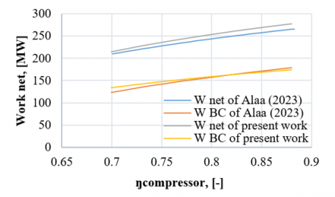
The impact of isentropic efficiency on the performance of air compressor and rate of overall cost. The data showed that an increase in AC corresponds to rise in net and GSO CC system efficiency. Increasing the AC will result in a decrease in the power needed to run the compressor, which will increase the power output of the gas turbine if the airflow rates remain constant. Total net rises from 215.6 MW to 275 MW with a change in AC from 70% to roughly 88%. The cycle's First- and Second-Law efficiencies would increase if AC was boosted. The findings suggest that raising AC is necessary to achieve improved efficiency. But this is not cost-effective. Based on these results, a reduced cycle's overall cost is obtained by boosting AC from 70% to roughly 84%. However, increasing AC further will increase the cycle's overall cost beyond 84% superfast. From Figure 2, it is evident that the similarities in the results obtained through the computational simulation process are that the error rate does not exceed 10%, which is a good percentage for comparison with previous research [20]. The gaps in the comparison topic were addressed so that the most efficient use was obtained from the high temperatures at the cycle output and the use of more than one ORC cycle.
Figure 2. Variation of Ẇnet with ηAC
6.2 Effect of the temperature ambient on combined cycle performance
Ambient temperature significantly impacts the performance of combined power cycles, including ORC units and GTC. Higher temperatures can reduce air density, affecting the compressor's efficiency and potentially leading to compressor stalling. The temperature differential between the heat source and cooling medium also affects ORC systems, with lower temperatures affecting the ORC cycle's efficiency. Higher exhaust gas temperatures can improve energy availability for ORC units, but may also affect the efficiency of the gas turbine cycle. Adequate cooling is essential for peak performance. These temperature-related interactions affect the combined cycle's overall efficiency and power production. Engineers must consider these effects when optimizing individual cycle efficiencies. Simulation and modeling can help fine-tune operational parameters and heat source consumption under different ambient temperatures. Figure 3 shows the effect of entry temperatures on the total efficiency of the system, as the increase in the entry temperature reduces the efficiency of the system, and therefore the entry temperature value of 51 degrees Celsius was the worst case, as the energy efficiency reached 38.5%, while the best temperature reached is at the temperature is 15 degrees Celsius, as the efficiency reached 40.01%. To better understand the impact of higher entry temperatures on system efficiency, it is essential to expand the results section. This involves explaining the phenomenon, comparing it with existing studies, discussing potential mitigation strategies, considering practical applications, and acknowledging limitations. By providing a detailed explanation of the phenomenon, comparing it with previous research, and discussing potential strategies, the results can be more comprehensive and provide context for interpretation. Additionally, discussing the practical implications of the findings for real-world applications, such as power plant design or energy conversion systems, can inform decision-making in industry or policy. Acknowledging any limitations and suggesting future research directions can help provide further insights into the relationship between entry temperatures and system efficiency. By addressing these aspects, the expanded results section can provide a more comprehensive understanding of the implications of higher entry temperatures on system efficiency.
Figure 3. Variation of η energy over all with ambient temperature.
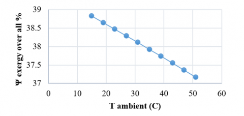
The impact of entry temperatures on the system's exergy is depicted in Figure 4, where the increase in the entry temperature reduces the exergy of the system, and therefore the entry temperature value of 51 degrees Celsius was the worst case, as the exergy reached 37.1%, while the best temperature was reached at temperature 15 Celsius degree, where the efficiency reached 38.9%.
Figure 4. Variation of Ψ exergy over all with ambient temperature
6.3 Effect of the pressure ratio on combined cycle performance
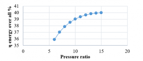
The pressure ratio significantly impacts the performance of combined power cycles, including ORC units and GTC. Higher pressure ratios require more labour, affecting the compression process and affecting the evaporating and condensing phases of the ORC system. Higher pressure ratios can improve the cycle's efficiency and heat transfer, while also affecting the temperature of exhaust gases, which affects the heat supply to ORC units. To maximize system performance, pressure ratios must be balanced, considering the power plant's unique requirements and potential heat recovery potential. Engineers and researchers must carefully consider pressure ratios, considering trade-offs between heat recovery potential and efficiency losses. Simulation and modeling tools can guide the design and operation of effectively combined power plants. Figure 5 shows the effect of pressure ratio on the total efficiency of the system, as the increase in the pressure ratio increase the efficiency of the system, and therefore the pressure ratio value of 6 was the worst case, as the energy efficiency reached 35.9%, while the best efficiency reached is at pressure ratio is 15, as the efficiency reached 40.01%.
Figure 6 shows the effect of pressure ratio on the exergy of the system, where the increase in the pressure ratio increases the exergy of the system, and therefore the pressure ratio value of 6 was the worst case, as the exergy reached 34.6%, while the best exergy was reached at pressure ratio 15, where the efficiency reached 38.7%.
Figure 5. Variation of η energy over all with pressure ratio
Figure 6. Variation of Ψ exergy over all with pressure ratio
6.4 Effect the compressor efficiency on combined cycle Performance
Compressor efficiency significantly impacts the performance of combined power cycles, including ORC units and GTC. Higher compressor efficiency reduces energy waste during compression, allowing more energy for combustion and power production. A larger mass flow rate of air enters the combustion chamber, improving combustion efficiency and cycle efficiency. In combined cycles, ORC units may be powered by waste heat from the gas turbine's exhaust, increasing heat recovery potential and overall cycle efficiency. A high-efficiency compressor design is essential for efficient combined cycles, considering trade-offs between efficiency, system complexity, cost, and total cycle efficiency. Engineers can enhance the efficiency of gas turbine and ORC cycles by increasing compressor efficiency. Figure 7 illustrates the effect of compressor efficiency on the total efficiency of the system, as the increase in the compressor efficiency increase the efficiency of the system, and therefore the compressor efficiency value of 70% was the worst case, as the energy efficiency reached 35.5%, while the best efficiency reached is at compressor efficiency is 90%, as the efficiency reached 42.4%.
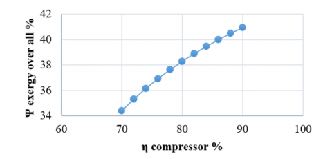
Figure 8 shows the impact of compressor efficiency on the system's exergy, where the increase in the compressor efficiency increases the exergy of the system, and therefore the compressor efficiency value of 70% was the worst case, as the exergy reached 34.5%, while the best exergy was reached at compressor efficiency 90%, where the efficiency reached 41%.
Figure 7. Variation of η energy over all with compressor efficiency
Figure 8. Variation of Ψ exergy over all with compressor efficiency
6.5 Effect of the temperature of exhaust on combined cycle performance
The performance of a combined power cycle, including ORC units and GTC, is significantly influenced by the temperature of exhaust gases. The efficiency and energy recovery of both cycles are directly correlated with the temperature of the exhaust gases. Higher exhaust gas temperatures increase thermal energy in the exhaust gases, improving heat recovery and ORC efficiency. However, higher exhaust gas temperatures can also increase emissions, particularly nitrogen oxides (NOx). Engineers must balance efficiency improvements and environmental effects to ensure the system's long-term reliability. The design and operation of a combined power plant can be influenced by evaluating the impact of different exhaust gas temperatures on the cycle's overall performance using simulation tools and comprehensive analysis. Figure 9 shows the effect of temperature of exhaust on the total efficiency of the system, as the increase in the temperature of exhaust reduce the efficiency of the system, and therefore the temperature of exhaust value of 300℃ was the worst case, as the energy efficiency reached 39.65%, while the best efficiency reached is at temperature of exhaust is 210℃, as the efficiency reached 40.9%.
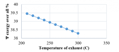
Figure 10 illustrates the impact of temperature of exhaust on the exergy of the system, where the rise in the temperature of exhaust reduces the exergy of the system, and therefore the temperature of exhaust value of 300℃ was the worst case, as the exergy reached 38.3%, while the best exergy was reached at temperature of exhaust 210℃, where the efficiency reached 39.5%.
Figure 9. Variation of η energy over all with temperature of exhaust
Figure 10. Variation of Ψ exergy over all with temperature of exhaust
The study reveals that higher entry temperatures reduce the system's total efficiency, with the worst case being 51 degrees Celsius, resulting in 38.5% energy efficiency. The best entry temperature is 15 degrees Celsius, with an efficiency of 40.01% and an exergy of 37.1%. The pressure ratio also impacts system efficiency and exergy, with higher ratios resulting in higher efficiency. The worst efficiency is 35.9% at a 6 ratio, while the best efficiency is 40.01% at a 15-point ratio. The compressor efficiency leads to higher total system efficiency, with a 70% efficiency value resulting in 35.5% energy efficiency. The exhaust temperature also affects efficiency, with higher temperatures resulting in reduced efficiency and decreased exergy.
|
GT |
gas turbine |
|
$\dot{W}$ |
work, Joule (J) |
|
h |
enthalpy |
|
ORT |
turbine natural Rankine |
|
$\dot{m}$ |
mass flow rate, kg/s |
|
P |
Product |
|
F |
Fuel |
|
$\dot{E}$ |
Exergy |
|
BC |
Brayton cycle |
|
HE |
intensity exchanger |
|
Greek symbols |
|
|
ε |
exergy efficiency |
|
Ψ |
exergy over all |
|
HRB |
intensity Recuperation Evaporator |
|
η |
isentropic efficiency |
|
Subscripts |
|
|
AC |
air blower |
|
CC |
burning chamber |
[1] Ibrahim, T.K., Mohammed, M.K., Awad, O.I., Abdalla, A.N., et al. (2018). A comprehensive review on the exergy analysis of combined cycle power plants. Renewable and Sustainable Energy Reviews, 90: 835-850. https://doi.org/10.1016/j.rser.2018.03.072
[2] Kotowicz, J., Brzęczek, M. (2018). Analysis of increasing efficiency of modern combined cycle power plant: A case study. Energy, 153: 90-99. https://doi.org/10.1016/j.energy.2018.04.030
[3] Sabouhi, H., Abbaspour, A., Fotuhi-Firuzabad, M., Dehghanian, P. (2016). Reliability modeling and availability analysis of combined cycle power plants. International Journal of Electrical Power & Energy Systems, 79: 108-119. https://doi.org/10.1016/j.ijepes.2016.01.007
[4] Kotowicz, J., Job, M., Brzęczek, M. (2015). The characteristics of ultramodern combined cycle power plants. Energy, 92: 197-211. https://doi.org/10.1016/j.energy.2015.04.006
[5] Mansouri, M.T., Ahmadi, P., Kaviri, A.G., Jaafar, M.N.M. (2012). Exergetic and economic evaluation of the effect of HRSG configurations on the performance of combined cycle power plants. Energy Conversion and Management, 58: 47-58. https://doi.org/10.1016/j.enconman.2011.12.020
[6] Ersayin, E., Ozgener, L. (2015). Performance analysis of combined cycle power plants: A case study. Renewable and Sustainable Energy Reviews, 43: 832-842. https://doi.org/10.1016/j.rser.2014.11.082
[7] Tică, A., Guéguen, H., Dumur, D., Faille, D., Davelaar, F. (2012). Design of a combined cycle power plant model for optimization. Applied Energy, 98: 256-265. https://doi.org/10.1016/j.apenergy.2012.03.032
[8] Liang, M.H., Luo, B., Zhi, L.J. (2009). Application of graphene and graphene-based materials in clean energy-related devices. International Journal of Energy Research, 33(13): 1161-1170. https://doi.org/10.1002/er.1598
[9] Petrakopoulou, F., Tsatsaronis, G., Morosuk, T., Carassai, A. (2012). Conventional and advanced exergetic analyses applied to a combined cycle power plant. Energy, 41(1): 146-152. https://doi.org/10.1016/j.energy.2011.05.028
[10] Ibrahim, T.K., Rahman, M.M., Abdalla, A.N. (2011). Gas turbine configuration for improving the performance of combined cycle power plant. Procedia Engineering, 15: 4216-4223. https://doi.org/10.1016/j.proeng.2011.08.791
[11] Shalan, H.E.M.A., Hassan, M.M., Bahgat, A. (2010). Comparative study on modeling of gas turbines in combined cycle power plants. In Proceedings of the 14th International Middle East Power Systems Conference (MEPCON’10), Cairo University, Egypt, pp. 970-976.
[12] Chacartegui, R., Sánchez, D., Muñoz, J.M., Sánchez, T. (2009). Alternative ORC bottoming cycles for combined cycle power plants. Applied Energy, 86(10): 2162-2170. https://doi.org/10.1016/j.apenergy.2009.02.016
[13] Alobaid, F., Postler, R., Ströhle, J., Epple, B., Kim, H.G. (2008). Modeling and investigation start-up procedures of a combined cycle power plant. Applied Energy, 85(12): 1173-1189. https://doi.org/10.1016/j.apenergy.2008.03.003
[14] Polyzakis, A.L., Koroneos, C., Xydis, G. (2008). Optimum gas turbine cycle for combined cycle power plant. Energy Conversion and Management, 49(4): 551-563. https://doi.org/10.1016/j.enconman.2007.08.002
[15] Koch, C., Cziesla, F., Tsatsaronis, G. (2007). Optimization of combined cycle power plants using evolutionary algorithms. Chemical Engineering and Processing: Process Intensification, 46(11): 1151-1159. https://doi.org/10.1016/j.cep.2006.06.025
[16] Cihan, A., Hacıhafızoglu, O., Kahveci, K. (2006). Energy-exergy analysis and modernization suggestions for a combined-cycle power plant. International Journal of Energy Research, 30(2): 115-126. https://doi.org/10.1002/er.1133
[17] Hosseini, R.E.Z.A., Soltani, M., Valizadeh, G. (2005). Technical and economic assessment of the integrated solar combined cycle power plants in Iran. Renewable Energy, 30(10): 1541-1555. https://doi.org/10.1016/j.renene.2004.11.005
[18] Cheng, K., Qin, J., Dang, C., Lv, C., Zhang, S., Bao, W. (2018). Thermodynamic analysis for high-power electricity generation systems based on closed-Brayton-cycle with finite cold source on hypersonic vehicles. International Journal of Hydrogen Energy, 43(31): 14762-14774. https://doi.org/10.1016/j.ijhydene.2018.05.138
[19] Vanek, F.M., Albright, L.D. (2008). Stationary combustion systems. In Energy Systems Engineering, pp. 125-162.
[20] Vanek, F.M., Albright, L.D., Angenent, L.T. (2012). Stationary combustion systems. In Energy Systems Engineering, pp. 161-167.