Farhad Hosseinlou![]() | Sajjad Tuama Oliewi
| Sajjad Tuama Oliewi![]() | Mojtaba Labibzadeh
| Mojtaba Labibzadeh![]() | Abdolghafour Khademalrasoul
| Abdolghafour Khademalrasoul![]() | Kadhim Z. Naser*
| Kadhim Z. Naser*![]()
© 2025 The authors. This article is published by IIETA and is licensed under the CC BY 4.0 license (http://creativecommons.org/licenses/by/4.0/).
OPEN ACCESS
Deep excavations in urban environments require effective stabilization, particularly under extreme conditions such as blast loads. Traditional bracing systems often lack sufficient resilience against dynamic forces. This study explores the performance of resilient-layer buckling restrained braces (RLBRBs) in diaphragm walls subjected to blast loading using finite element analysis (FEA) in Abaqus. The research examines the effects of pit width, depth, soil properties, and blast location on excavation stability, along with the role of dampers in mitigating blast effects. The results show that narrower pits (8 m and 16 m) absorb more energy (20–45%) but experience lower lateral displacement, whereas wider pits (20 m) improve plasticity and energy dissipation. Increasing pit depth initially reduces blast energy effects, but beyond 20 m, energy absorption rises sharply, indicating instability risks. Soil properties significantly influence stability, with higher cohesion and internal friction angles enhancing resistance and reducing stresses on struts. The blast position is critical, with bottom-layer explosions generating up to 8 times more energy than surface explosions. The study demonstrates that RLBRB-equipped struts enhance structural stability compared to conventional braces. Additionally, viscoelastic dampers reduce blast energy by up to 25%, though their efficiency decreases in deeper excavations. These findings provide a framework for safer urban excavation designs, with applications in subway systems and high-risk infrastructure.
pit stabilization, blast load, finite element analysis, RLBRB diaphragm walls, energy reduction
In recent years, drilling accidents have occurred frequently. These accidents include foundation pit collapses, water leaks, ground subsidence, tilting of nearby buildings, gas pipeline leaks and even explosions [1, 2]. Additionally, deep excavations in urban environments are essential for the construction of large buildings. However, these megaprojects are highly susceptible to damage, especially when built on soft soil formations. Problematic soils, such as soft clay and loose sand, are commonly encountered by engineers [3-5]. Based on global databases, the deflection of retaining walls can be estimated using both empirical and semi-empirical methods [6]. Furthermore, several researchers have introduced modifications to Clough’s empirical approach [7-11].
Construction restrictions often require basements for various uses, necessitating excavation below the foundation level. Stabilization and securing the pit wall are crucial for stability and preventing collapse of nearby buildings. Methods include piling, shielding, construction from top to bottom, nailing, mutual restraint and anchoring, and truss. These methods can be implemented separately or in combination, and are typically used in large projects. The first step is to check ground strength, soil type, and road conditions. Underground facilities should be identified and protected, and wells should be checked to prevent water from entering the pit. Soil pressure containment, also known as mutual containment, is a method used to stabilize pits with small widths, often without neighbor permission. It involves installing vertical members at intervals and placing a horizontal member between them to prevent wall deformation [12-14]. Figure 1 shows the stabilization of pit walls using strut method in Sepidar project [14].
The mutual containment method uses pressure members to transfer soil pressure. Walls, compression members, and intermediate members are key components. Walls resist soil pressure and act as supports for compression members, such as shields, diaphragmatic walls, metal guardian piles, and concrete guardian piles. Compression members transfer soil pressure from one wall to another, with different types including IPE couple profiles, IPB couple profiles, pipe profiles, and concrete sections. Intermediate members transfer force from the wall to compression members, with struts and connections designed based on compressive force, shear and bending force, and combined forces. The method considers buckling in horizontal members and may require diagonal cross braces for optimal design [15-19].
Figure 1. Stabilization of pit walls using strut method in Sepidar project [3]
Based on what was said and considering the title of the research, the following important points can be stated. Explosive interactions release large amounts of energy in the form of heat and pressure, creating a wave called an explosion wave. This wave can cause extensive damage to various structures. Explosions can be based on nuclear, chemical, or nuclear factors. High-temperature gases are produced, which rapidly expand and push trapped air out of the space. Compressed air forms in front of these gases, releasing the most energy. Explosions are divided into external, internal, and underground types, with external explosions being spherical and ground level explosions spreading in a hemisphere. The effects of physical impact, shrapnel impact, and earth shock during external explosions should also be considered [20, 21].
Structures that aren't resistant to explosions tend to collapse under the force of the blast. The issue becomes more serious in excavations, particularly in areas with soft soils or deep pits, because of the potential for the brace to collapse suddenly. Variables such as explosion power, site, soil composition, resistance traits, and pit shape are all part of the parametric investigation. A further complication is the intricacy of the issue as a result of software modelling and the behavior of soil and rock under applied stresses. The strut a system that safeguards excavated pits on loose soils is the subject of this study.
Diaphragm walls are a widely used method for stabilizing deep excavations, particularly in foundation construction and subway station projects. Understanding the behavior of retaining walls is essential for geotechnical engineers and designers to ensure the accuracy of their design and implementation. The presence of soft soils significantly influences the performance of diaphragm walls, and inadequate design may result in excessive settlement and deformation beyond permissible limits.
Stabilization systems can be categorized into three types based on their power requirements. Active systems depend on a continuous external power source, limiting their applicability in seismic conditions. Semi-active systems require minimal external energy and function without a global monitoring system. In contrast, passive systems operate independently, without the need for an external power supply, actuators, or computational control.
Buckling-Restrained Braces (BRBs) are structural steel elements designed to provide stability and dissipate energy, making them particularly useful in seismic and blast-resistant applications. However, deep excavations are often susceptible to underground explosions, which can cause significant damage to structural systems due to the impact of buried detonations in the soil [22-25].
The resilient-layer buckling restrained braces (RLBRB) struts and the conventional methods are characterized by a very high resistance to buckling, unlike the conventional struts which are low in the challenges of buckling. Also, the RLBRB struts are characterized by being very good in dissipating energy, while the conventional struts are average in dissipating energy and rely on their plasticity. The RLBRB struts differ from the conventional ones in being efficient in terms of weight, materials and flexibility. They also feature the ease of the adjustable layered design, while the conventional ones are less flexible. The supports have a steel core to carry axial loads as in conventional BRB supports and this core is surrounded by flexible restraining layers to prevent local buckling and these layers are either composite coatings or flexible steel sheets. There are several areas of development and innovation in the applications of this type of supports, including those related to engineering developments in design or the use of advanced materials or in terms of durability and cost savings.
Urban constructions and limited space make it challenging to choose effective pit stabilization methods. Mehrabandi, with opposite struts, is a suitable solution with safety and easy reinforcement. Factors like soil parameters, explosion type, pit dimensions, and software modeling need comprehensive parameter studies for successful implementation. The research examines the impact of explosions on excavations, analyzing pit design under static and seismic loads, and the impact of earthquakes on pit bracing system's internal forces. It aims to provide comprehensive evaluation and design of pits for optimal efficiency and energy absorption.
This study investigates the effectiveness of reduced-length buckling-restrained braces (RLBRBs) in enhancing the stability of excavation pits subjected to blast loads using finite element analysis (FEA). It assesses key parameters affecting excavation stability, including the influence of pit width, depth, and soil properties on energy absorption and displacement, as well as the impact of explosion position on structural damage. Based on these findings, the study develops blast-resistant pit design guidelines, providing recommendations for optimal pit dimensions, reinforcement strategies, and material selection to improve stability and resilience under dynamic loading.
To conduct this research, the drilling and pit model, as shown in Figure 2, was utilized as the foundation for the study. This model was also employed for software validation, incorporating three distinct soil layers:
1) A 1–3 m layer of disturbed topsoil and fill,
2) A 3–25 m layer of soft soil, and
3) A 25–50 m layer of medium stiff clay. The groundwater table was assumed to be at the surface level.
For soil modeling, the Mohr-Coulomb model was adopted as the constitutive model for Layers 1 and 3, while the modified Cam-Clay model was applied to Layer 2. The diaphragm walls were designed with a length of 25 m, incorporating a stiffness system consisting of 1 m-thick diaphragm walls and pipe-shaped struts with an outer diameter of 609 mm and a thickness of 16 mm. The excavation components were designed following the recommendations of Chowdhury et al. [26]. In this context, the embedded depth of the diaphragm walls ($Db$) was set to be at least 80% of the excavation depth ($De$), while the wall thickness (twall) was set to a minimum of 6% of (De).
The struts were designed using steel St37, with a Young’s modulus of $E$ = 2e8 kN/m² and a yield stress of $F y$ = 2350 kN/m². The structural design for the struts followed the guidelines of AISC 341-10 [27]. Internal axial forces in the struts were determined based on the approach of Terzaghi et al. [28].
The maximum allowable lateral deflection of the retaining wall, as proposed by Clough [29], is given by deflection=0.5H max., which corresponds to a maximum permissible deflection of 70 mm based on the wall depth. However, numerical modeling conducted on the considered excavations (Figure 2) revealed that the maximum lateral wall deflection at the final excavation stage was 35 mm [29], remaining well within the allowable limit.
Figure 2. Schematic of the excavation investigated in this research for the purpose of parametric studies [29]
The results indicated a sufficient margin of safety in the wall's performance. Given that Clough's [29] system stiffness factor does not fully capture the true behavior of deep excavations, Bryson and Zapata-Medina [30] introduced a relative stiffness ratio to better represent this relationship [31]. As following:
$R=\frac{E_s}{E} * \frac{S_h S_v H}{I} * \frac{\gamma_S H_e}{S_u}$ (1)
In this context, Es represents the Young’s modulus of the soil, while E denotes the Young’s modulus of the wall. The parameter $E$ corresponds to the moment of inertia per unit length of the wall, SH and SV represent the average horizontal and vertical support spacings, respectively, and $H$ is the total height of the wall. Additionally, He denotes the excavation depth, γs is the average unit weight of the soil, and Su refers to the undrained shear strength of the soil at the excavation base.
Following this, the factor of safety against basal heave was determined using Terzaghi’s equation, as reported by Ukritchon et al. [32], as shown below [31]:
$F_s=\frac{S_u N_c+\sqrt{2} S_u\left(\frac{H}{B}\right)+2 S_u\left(\frac{D}{B}\right)}{I \gamma_S H_e}$ (2)
here, $Su$ represents the average undrained shear strength of the retained soil, while Nc is the bearing capacity factor at the excavation base. The excavation height is denoted as He, the excavation width as $B$, and the embedment depth below the excavation bottom as $D$. Additionally, $\gamma s$ refers to the unit weight of the soil.
Based on the obtained relative stiffness ratio exceeding 0.1 and a factor of safety against basal heave of 1.2, the maximum deflection-to-total-wall-height ratio, as per the diagram by Bryson and Zapata-Medina [30], is 0.12%$H$. Consequently, the maximum lateral deflection of the diaphragm wall was determined to be 45 mm. Given that the modeled diaphragm walls exhibited a lateral deflection of 35 mm, they remained within the allowable design limits (Figure 2). The soil properties are detailed in Tables 1 and 2 [31].
Table 1. The mechanical characteristics of the soil layers [31]
|
Soil Parameters |
Unit |
Fill (1) |
Very Soft to Soft Muddy Clay (2) |
Soft to Stiff Clay (3) |
|
Soil Model for FE modeling |
- |
M.C |
MCC |
M.C |
|
ρ |
Kg/m3 |
700 |
650-850 |
950 |
|
E |
MN/m2 |
60 |
- |
24-40 |
|
φ |
Degree |
33 |
- |
1 |
|
C |
KN/m2 |
15 |
- |
25-60 |
|
K |
m/s |
0.00086 |
0.00514 |
0.0077-0.017 |
|
E (void ratio) |
- |
1 |
1.6 |
0.8 |
Table 2. Properties of modified cam-clay model for third layer [31]
|
Comparison Index (λ) |
Flow Stress Ratio (K) |
Poisson Ratio (υ) |
Log Bulk Modulus |
Slope of CSL in q-p Space M |
|
0.16-0.19 |
0.79 |
0.2 |
0.045 |
0.8-0.875 |
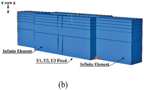
The numerical model of the problem is shown in Figure 3. In the figure on the left, the numerical model is shown for the purpose of stress analysis (for geostatic analysis) and in the figure on the right, the numerical model is shown for the purpose of seismic dynamic analysis. In seismic dynamic analysis and in the corresponding model, unlimited elements are considered, and in simpler terms, in general, in dynamic analyzes, in order to prevent the conditions of wave reflection at the boundaries, the mentioned elements are used, which in the analyzes Static is not needed. In fact, the intended study in this research is based on this model [31].
Figure 3. Numerical model for static analysis and seismic dynamic analysis [31]
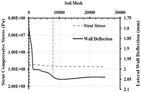
Figure 4 shows the changes in axial force and stress in the stratum based on the number of elements determined through meshing or elementing. This sensitivity analysis is crucial in the finite element method, as it depends on the meshing sensitivity and the size and dimensions of the elements. Fine meshing results in softer behavior, while coarse meshing leads to harder behavior and higher stresses. It is recommended to use a medium mesh size as a first approximation. Finer meshing leads to softer behavior and increased deformations, with a constant rate up to 10,000 elements. The internal force and tension in the stratum increase due to the increased softness and lateral displacement of the wall. The soil tension decreases with the number of elements, while the strength of the struts increases.
Figure 4. Changes in axial force or stress created in struts. Lateral displacement of the drilling wall based on the number of elements [31]
The constitutive model significantly impacts results, and its choice depends on the engineer's experience and site conditions. Simple, common behavioral models like the Mohr-Coulomb are suitable for approximation and initial evaluation in geotechnical problems. Advanced models like hardening soil or general low-level models can be used if parameters are available. The correlation between Drucker-Prager and Cam-Clay behavioral models and the Mohr-Coulomb model is discussed, allowing for parameter determination based on these relationships [31].
$\tan \beta=\frac{3 \sqrt{3} \tan \varphi}{\sqrt{9+12 \tan ^2 \varphi}}$ (3)
$d=\frac{3 \sqrt{3} c}{\sqrt{9+12 \tan ^2 \varphi}}$ (4)
The following relationships are also used to express the correlation between the parameters of the low-general behavior model and the Mohr-Coulomb behavior model. The three important parameters for the low general behavior model include the following parameters [31].
$k=\frac{C_s}{2.3}$ (5)
$\lambda=\frac{C_c}{2.3}$ (6)
$M=\frac{6 sin \phi}{3-sin \phi}$ (7)
This research examines the impact of soil mechanical parameters on results, including cohesion parameters, internal friction angle, modulus of elasticity, Poisson's coefficient, soil density, and stability conditions of pits. The study investigates the stability of the pit, displacement, stresses, and energy caused by the explosion based on the amount of explosive material, distance, and explosion intensity. The finite element method and Abaqus software are used to conduct the research, which analyzes the pit and support system under normal conditions, before and after an explosion, and based on different intensities. The explosion function is entered based on the explosion intensity value. For example, for the amount of TNT equal to 2000 kg and the explosion distance of 1 meter, the explosive pressure value is approximately equal to 600 kilopascals, which is in the function curve of this pressure. An explosion is shown in Figure 5.
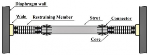
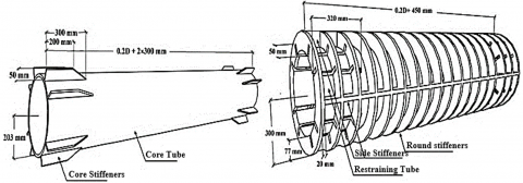
The geometry of the problem includes the geometry of the soil, which is three-dimensional (volumetric), and the geometry of the wall, which can be three-dimensional shell or volume, and the geometry of stratum elements. The stratum is of composite type, which have three components, namely the covering part - the central core of the covering - the middle and main part, and for their modeling, a combination of volume and shell or linear elements are used, and these elements are coupled to each other. and are connected as demonstrated in Figure 6.
Figure 5. The curve of the explosion pressure function for the explosion pressure is 600 kilopascals [19]
(a)
(b)
(c)
Figure 6. Details and geometry of support system
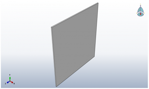
The first step: making a geometric model of each of the model's components, as shown in Figures 7 and 8.
Second step: defining the specifications of materials and specifications of sections. In this case, Drucker-Prager model is considered for the soil. Two types of steel and concrete materials are defined for the strut, which is made of steel element and core (concrete or steel) and steel restraining elements of the type of linear elements. It should be noted that elastic and plastic characteristics for steel and cracking characteristics for concrete should be defined in this section. Next, the strut components are assembled to create the strut.
Figure 7. Geometric model of excavation in Abaqus software
Figure 8. Geometric model of diaphragm wall in Abaqus software
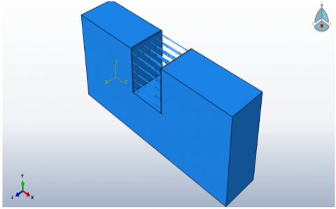
The third step: assembling all the components of the model, including strut, wall and soil, and producing the final model as displayed in Figure 9.
The fourth step: defining the type of analysis and explosive loading function and applying the explosive load to the numerical model
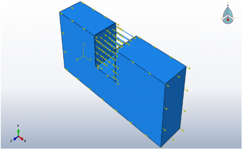
Fifth step: definition of loading and support boundary conditions as shown in Figure 10.
Sixth step: meshing (elementalization) of the model as shown in Figure 11.
Figure 9. The final model assembled in the software
Figure 10. Applying blast load to the model (volume loading)
Figure 11. Meshing of the model and its components
Finally, the model is analyzed and the outputs are checked. These outputs include changes in locations for monitoring points and shear stress distribution created under barrage and energy distribution, which is the amount of energy resulting from the blast load as a criterion for evaluating and determining the optimal bracing system design. In this regard, it is better and necessary to evaluate and compare the normal strut system and the strut in question in this research under the blast load. The system that has the minimum amount of energy is considered as the optimal system, and if the system in question in this research has less energy than the conventional system, it can be concluded that this system has the ability to absorb and dissipate energy. This issue is subject to investigation and evaluation and parameter studies that will be discussed in the next chapter.
In this part of the research, two issues are considered for the purpose of software validation. The first case is related to the tubular pile elements buried in the soil under the blast load, during which the problem of modeling the blast load and its effect on the buried elements is evaluated while evaluating the results of the software, and the second problem is the evaluation of the seismic behavior of drilling with a bracing system. It is intended, based on which, while evaluating the results of the geometric modeling software and the elements used in the research problem, dynamic loading on the model and struts and the relevant results are examined.
4.1. Evaluation of the behavior of tubular piles buried in soil under blast load
Before performing the modeling operation, which in this research is based on the use of Abaqus software, it is necessary to perform the validation process of the software and the modeling procedure. Therefore, validation is done firstly with the purpose of testing the results of the software used and secondly evaluating the correct modeling procedure. For this purpose, the research and study done by Chakraborty [33], and Khademalrasoul and Amerikhah [34].
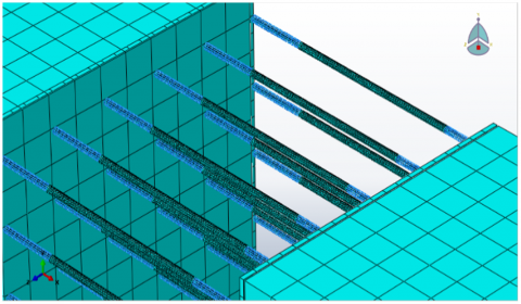
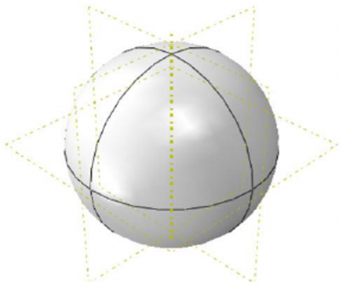
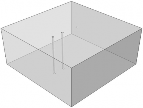
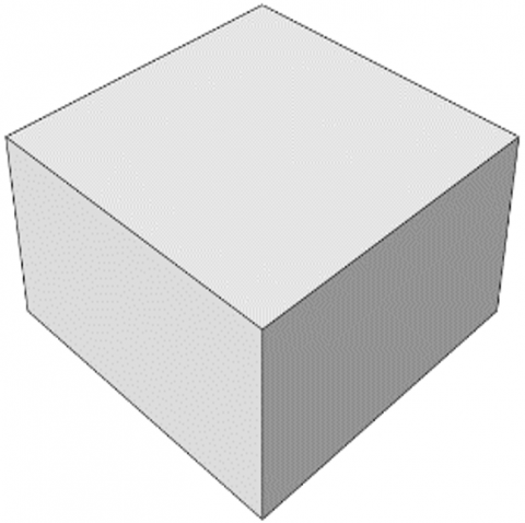
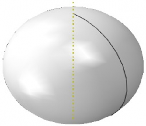
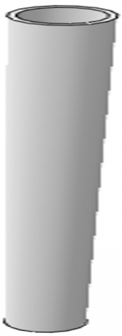
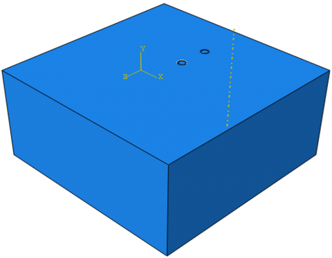
In this research [33], the modeling of underground explosion and its effect on two adjacent buried pipes have been discussed. The explosive substance was located at a horizontal distance of 4 meters from the first pipe and at a distance of 35 cm from the soil surface. The amount of explosive was 50 kg. The simulation details are presented below. The soil model had dimensions of 20*20*10 meters, and the soil geometry is presented in Figure 12. The amount of explosive substance was equal to 50 kg, and according to the density of the explosive substance, its radius is considered to be 0.195 meters. The geometry of the explosive material is also presented in Figure 13. A Eulerian object is used to simulate and place the soil inside it and simulate the explosive substance and the spread of the explosion caused by the explosive substance in the analysis, and in other words, CEL analysis is used in this research. The space above the soil is also considered as an air volume see Figure 14. The pipes used in the model had an external diameter of 400 mm and an internal diameter of 335 mm. A schematic of these pipes is also presented in Figure 15 [33].
Figure 12. Soil geometry modeled [33]
Figure 13. TNT geometry modeled [33]
Figure 14. The geometry of the Eulerian section used in the analysis [33]
Figure 15. Geometry of steel pipes buried in soil [33]
Table 3. Soil properties used with the Drucker- Prager model [33]
|
Density (kg/m3) |
Elastic Modulus (MPa) |
Friction Angle (degree) |
Poisson Ratio |
|
1560 |
28 |
30 |
0.2 |
Table 4. Properties of TNT [33]
|
A (MPa) |
B (MPa) |
ω |
R1 |
R2 |
Detonation Energy Density (kJ/kg) |
|
373.8 |
3.747 |
0.35 |
4.15 |
0.9 |
3.68 |
|
Explosive |
Density (kg/m3) |
Detonation wave speed (m/s) |
|||
|
TNT |
1630 |
6.93 |
|||
Table 5. Steel properties with Johnson Cook model [33]
|
E (Gpa) |
υ |
A (MPa) |
B (MPa) |
n |
C |
|
200 |
0.3 |
360 |
635 |
0.114 |
0.075 |
The materials used in this research include soil, air, TNT and steel used in pipes. The properties of soil, TNT and steel are presented in Tables 3-5 respectively. Drucker-Prager model was used for soil, ideal gas model was used forair, Johnson Cook model was used for steel, and JWL model was used for TNT [33].
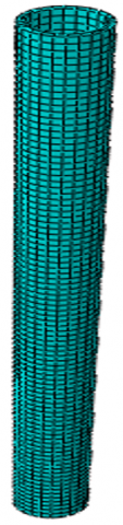
Next, modeling is done in Abaqus software and the results are evaluated. The modeling procedure is shown step by step below [33] in Figures 16-18.
Figure 16. Model components in Abaqus software
Figure 17. Final model and loading and boundary conditions and model components
Figure 18. Element arrangement (mesh arrangement) of model components and final model
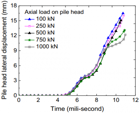
The results of the analysis of the reference article are shown in Figure 19. In this part, the problem is reanalyzed only for two load states and axial loads equal to 500 and 1000 kilonewtons, and the results obtained from the analysis of the reference article and the author's analysis are compared and the relative error between the results is evaluated. In the curves of Figure 20, the results of the analysis of the article and the author's analysis are compared, which are for axial loads of 500 and 100 kilonewtons.
Figure 19. Pile head displacement under the effect of axial loading and for different load values [33]
Figure 20. Comparison of the lateral displacement curves of the pile head versus time under torrential rain from the study (results of the article) and the current study for axial load of 500 and 1000 kilonewtons
The obtained results showed that the relative error of the results increases with the increase of the axial load on the pile head. In order to reduce the error, the meshing size can be changed by changing the axial load value to reduce the relative error percentage. Therefore, for the axial load of 500 kilonewtons, the relative error was about 8% and for the axial load of 1000 kilonewtons, the relative error was about 12% (with an average of 10% in total), which is very appropriate and logical and within the conventional range. It should be noted that in geotechnical issues, the maximum error in the range of 30% is also due to issues such as estimation of soil parameters - behavioral model - method of modeling and elements used - instrumental and human errors and device calibration (in the study of physical models). And the complexity of soil behavior under loading, etc. is also expected and can be reasonable. Depending on the complexity and conditions of the studied problem, the determination of the permissible range of error is usually determined by the researcher and with engineering judgment.
4.2 Analysis of soft soil-structure interaction using RLBRB-equipped strut in deep excavations
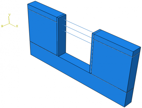
To validate the accuracy of the drilling model, as illustrated in the referenced figure and described in the research methodology, the model was developed using Abaqus software. Although the problem could be simplified to a two-dimensional analysis, the intricate details of the struts necessitate a three-dimensional approach. The soil profile consists of three distinct layers: (1) a disturbed topsoil and fill extending from 1 to 3 meters, (2) a soft soil layer from 3 to 25 meters, and (3) a medium-stiff clay layer from 25 to 50 meters. The water table is assumed to be at the ground surface.
For the soil constitutive models, the Mohr-Coulomb model was applied to Layers 1 and 3, while the modified Cam-Clay model was used for Layer 2. The diaphragm walls were designed to extend 25 meters deep, with a thickness of 1 meter. The structural system includes diaphragm walls and pipe-shaped struts, with the latter having an outer diameter of 609 mm and a wall thickness of 16 mm. The specific soil properties, previously detailed in Tables 1 and 2, are not reiterated here. As depicted in Figure 21, these parameters were incorporated into the model.
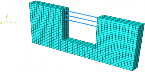
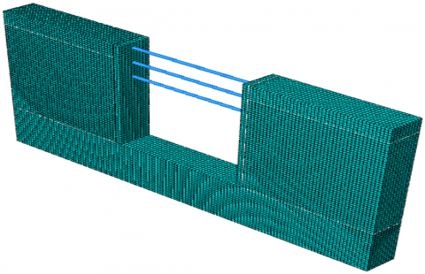
Instead of modeling the details of the strut and the complexity of the model, which can lead to numerical errors and incorrect results, the equivalent section and simple model and linear components can be used for the modeling of the strut. In this way, it is possible to evaluate both the internal forces and the stresses in the stratum. Next, modeling is done and the results are evaluated and compared with the results of the reference article. For the purpose of research, the excavation width is considered equal to 20 meters as shown in Figure 22.
Figure 21. Strut-reinforced pit model for verification purposes [33]
Figure 22. The geometric model of the pit in Abaqus software and its meshing
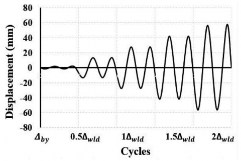
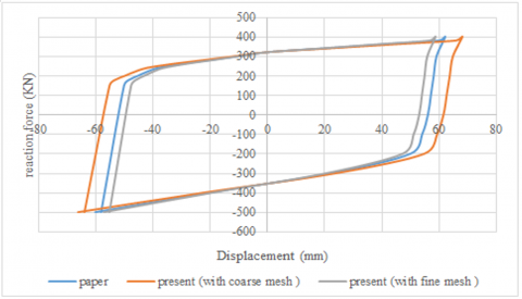
In this research, cyclic loading is considered. Cyclic loading is used for validation. In this regard, the load with the nature of forced relocation must be increased periodically and upward at a certain time, and based on that, the cyclical curve of displacement force is extracted as shown in Figure 23.
Figure 23. Cyclic loading curve [31]
(a)
(b)
Figure 24. (a) Model with fine mesh; (b) Comparison of deformation load curves obtained from the analysis of the reference [31] and the author's analysis with medium and fine meshing
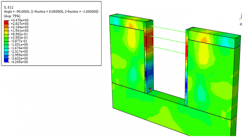
Figure 25. Shear stress distribution contours in the model under the effect of cyclic loading
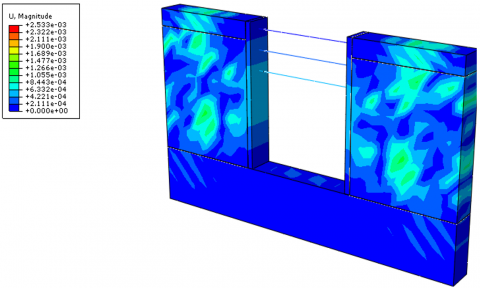
Figure 26. Deformation distribution contours in the model under the effect of cyclic loading
Figure 27. Contours of acceleration distribution due to cyclic loading
Figure 28. Stresses created in stratum due to cyclic loading
The results of the analysis showed that if medium meshing is used, there is a relative error of about 15%, and for fine meshing, which is shown further, the relative error is 5%, and therefore, the use of fine meshing for the desired problem is suitable for the modeling and analysis of samples and parametric studies in the next chapter of the work clock as shown in Figures 24-28.
4.3 Research scenarios
This study explores five research scenarios to determine the impact of blast loads on excavation stability. It evaluates the effect of pit width (8 m, 16 m, 20 m) at a fixed depth of 14 m and the effect of pit depth (8 m, 14 m, 20 m) at a fixed width of 20m on structural behavior under explosions. Additionally, it examines the influence of soil characteristics, including cohesion and internal friction angle, on blast response. The study also assesses the impact of explosion location at the bottom, middle, and top layers of the pit and analyzes the dimensional characteristics of soil struts in resisting blast forces. In all cases, the objectives are to determine the displacement at the top of the pit, evaluate stress distribution in the soil and struts, and analyze energy dissipation from the explosion over time.
5.1 Investigating the effect of pit width on its behavior and bracing system under blast load
In the first part of the study, the pit behavior is evaluated based on the pit width parameter. In this regard, as mentioned, widths of 8, 16 and 20 meters are considered for the pit. The geometric model and parameters were the same as the model that was considered for software validation, and the only difference between this model and the previous model is the type of load, which is the type of explosion load. The explosion load is considered in the software based on the function of the time load intensity that was stated in the previous chapter and is applied to it at the surface of the pit within a certain range. For all models, the peripheral boundaries are free in the vertical direction and closed in other directions. The walls and the excavation floor are completely free and the model floor is closed in all directions. The explosion charge is a volumetric charge in all directions. It should be noted that the explosion takes place within the model range and not at different distances outside the model range as demonstrated in Figures 29-37.
Figure 29. Numerical model of a pit with a width of 8, 16, 20 meters and its meshing and boundary conditions of support and loading for one of the samples
Figure 30. Blasting progress stages for a 20-meter-wide excavation sample
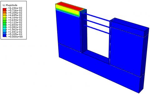
Figure 31. Deformation distribution contours for a pit with a width of 20 meters under the effect of blast load
Figure 32. Shear stress distribution contours for a pit with a width of 20 meters under the effect of blast load
Figure 33. Acceleration distribution contours for a pit with a width of 20 meters under the effect of blast load
Figure 34. Stress distribution contours of concretes for a 20-meter-wide pit under the effect of blast load
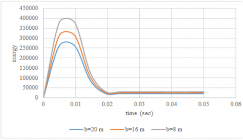
Figure 35. Excavation time energy curves for 8, 16 and 20 meter wide pits
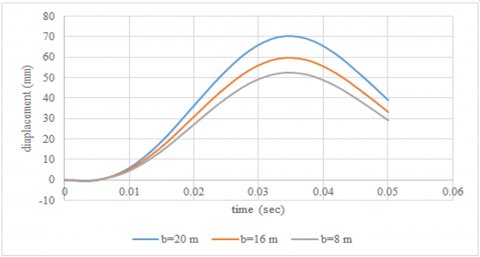
Figure 36. Lateral displacement curves of displacement time for 8, 16 and 20 meter wide pits
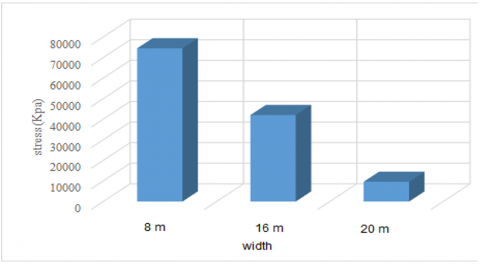
Figure 37. Comparison of the maximum stress of struts for pits with a width of 8, 16 and 20 meters
The results of the analysis showed that the maximum energy value increases by 20 and 45% for pits with a width of 16 and 8 meters, respectively, compared to a pit with a width of 20 meters. Also, the lateral displacement of the top of the pit is reduced by 15 and 25 percent for 16 and 8 meter pits, respectively. The increase in pit energy by reducing the width of the pit is due to the increase in hardness and the decrease in ductility, and as a result, the decrease in energy absorption and consumption is caused by the blast load, which is not desirable, but it is reduced due to the increase in hardness of the top of the pit. Also, the tension or the internal force of the stratum is equal to 1.8 and 4.4 times that of the pit with a width of 20 meters under the effect of the blast load, respectively, for pits with widths of 8 and 16 meters. Therefore, by increasing the width of the pit, the plasticity has increased and the ability to absorb and dissipate energy has increased, which in general leads to the reduction of the internal forces of the struts, but the lateral displacement of the pit has increased with the increase in the width of the pit, which in order to reduce it. The stiffness of the wall or struts can be increased. It is better and it is recommended that the thickness of the wall be somewhat increased in order to control the lateral displacement and that the struts always have high plasticity and their hardness is increased to a small extent.
5.2 Investigating the effect of pit depth on its behavior and bracing system under blast load
In this part of the research, the influence of the height of the pit on its behavior under heavy rain is investigated. For this purpose, pits with a height of 8, 14 and 20 meters are considered. The width of the pit is assumed to be fixed and equal to 20 meters as displayed in Figures 38-40.
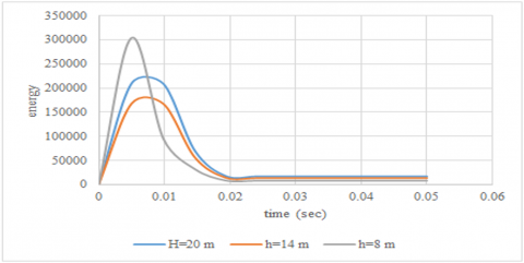
Figure 38. Excavation time energy curves for 8, 14 and 20 meter height pits
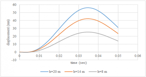
Figure 39. Lateral displacement curves of displacement time for 8, 14 and 20 meter height pits
Figure 40. Comparison of the maximum stress of struts for pits with a depth of 8, 14 and 20 meters
The obtained results showed that the amount of energy decreases with the increase of the height of the pit and as a result of its increase in plasticity (decrease in the hardness of the model along with the increase in dimensions and height of the pit), but this statement is correct up to a certain height and for very deep pits, the energy increases exponentially. has from a height onwards that this is an alarm in the direction of pit instability and not an increase in its plasticity (in which case the energy should be reduced). Therefore, the results showed that the energy of the pit decreased from 8 to 14 meters with the increase in depth, which is desirable, but for the 20-meter pit, the energy increased to about 60% and exponentially. But the interesting thing is that the energy rapidly drops in the future, which can be attributed to the high plasticity of the deep pit. Of course, it should be noted that the pressure caused by the explosion initially increased the pit's tendency to become unstable, but if the pit has a proper, accurate and principled bracing system, it can absorb and dissipate a large percentage of energy while quickly recovering stability with the help of its high plasticity. However, the displacement of the pit has always increased with the increase of the depth of the pit and for relatively deep and deep pits, and in some cases, it can lead to the overall instability of the pit.
5.3 The effect of soil parameters on pit behavior and stresses created in stratum due to blast load
In this part of the research, the effect of soil parameters on the behavior of the pit and the stresses caused by the blast load is investigated. In this regard, only for the second (middle) layer, which includes a greater part of the height of the pit, the soil parameters are changed and the results are checked. In this regard, the angle of internal friction is considered to be 10, 20, and 30 degrees, cohesion is considered to be 50, 100, and 150 kilonewtons per square meter, and the specific weight is considered to be 850, 1400, and 1800 kilograms per cubic meter (one of parameters are the main variables and other parameters have a fixed value. As shown in Figures 41-43.
Figure 41. Excavation time energy curves for phi=10, 20, 30 degrees
Figure 42. Lateral displacement curves of displacement time for phi=10, 20, 30 degrees
Figure 43. Comparison of the maximum stress of struts for phi=10, 20, 30 degrees
The obtained results showed that with the increase of the internal friction angle from 10 to 20 degrees, the energy increases, which was about 35%, but for the internal friction angle of 30 degrees, the energy increased by 25%, and this amount is less than that for the range of internal friction angle is 10 to 20 degrees. This shows that increasing the angle of internal friction to a certain extent leads to an increase in hardness, which increases the energy, but for higher values of the angle of internal friction, it does not play an unfavorable role, and the increase in soil resistance somehow leads to a decrease in energy, which is very It is interesting. Also, with the increase of the internal friction angle, especially in the range of 20 to 30 degrees, a very significant amount of lateral displacement is planted, which is very desirable. Also, the stresses created in the stratum decrease with the increase of the internal friction angle of the soil, and this is due to the increase in soil resistance for higher internal friction angles and the reduction of deformations and lateral displacement, and as a result, the force and pressure exerted by the soil on the stratum are reduced as demonstrated in Figures 44-46.
Figure 44. Excavation time energy curves for C=50, 100, 150 KPa
Figure 45. Lateral displacement curves of displacement time for C=50, 100, 150 Kpa
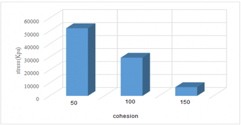
Figure 46. Comparison of the maximum stress of struts for C=50, 100, 150 KPa
The obtained results showed that the increase of 2 and 3 times the amount of cohesion leads to a decrease in energy by 25 and 45 percent, which is very desirable. The difference between cohesion and angle of internal friction is in their nature, in such a way that the increase of cohesion (which is an important resistance parameter in fine-grained clay soils) leads to an increase in ductility, as a result of which the soil resistance increases, but the increase in the angle of internal friction (which in especially for coarse-grained soils) it is synonymous with increasing resistance through friction between the solid grains of the soil, and somehow the hardness of the soil increases, which results in an increase in energy.
5.4 The effect of explosion position on pit behavior and the forces and tension created in struts
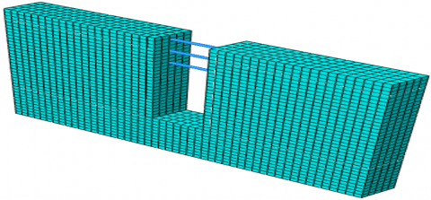
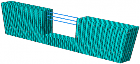
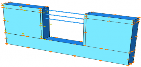
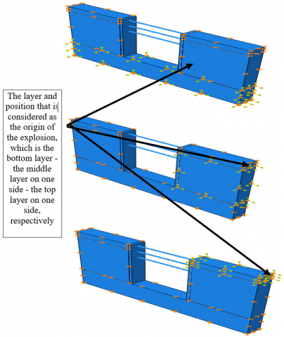
Finally, the impact of the explosion position on the behavior of the well and the results will be investigated. In this regard, 4 explosion positions are considered at the bottom, middle and top of the pit wall and pit floor. Each of the positions is shown below. In order to prevent tension build-up and to be realistic, it is assumed that the explosion will happen in three positions, in the bottom layer of the pit, in the middle layer on one side, and in the upper layer on one side of the pit wall see Figures 47-52.
Figure 47. Different explosion positions
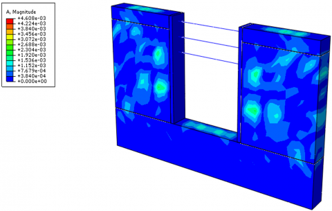
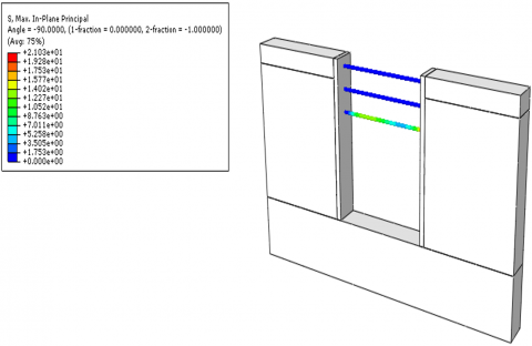
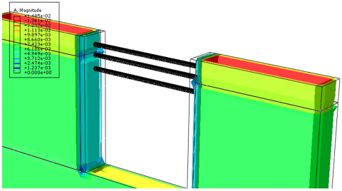
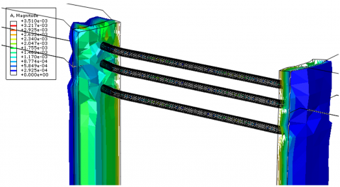
Figure 48. Stress distribution in the model and elements and the critical restraining element for explosion in the position of the upper layer
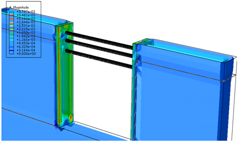
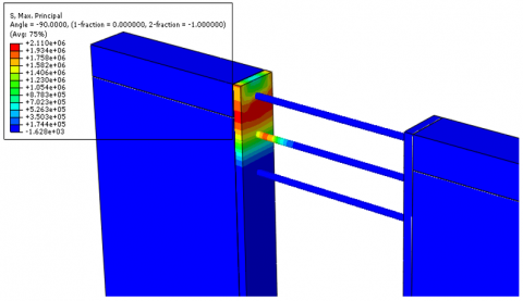
Figure 49. Stress distribution in the model and elements and the critical restraining element for explosion in the position of the middle layer
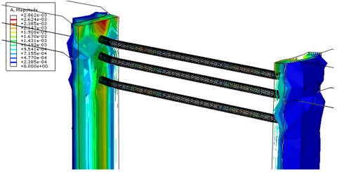
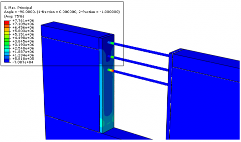
Figure 50. Stress distribution in the model and elements and the critical restraining element for explosion in the position of the lower layer
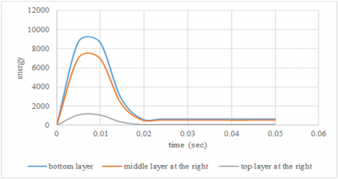
Figure 51. Comparison of energy curves based on different explosion positions
Figure 52. Comparison of displacement curves based on different explosion positions
The results of this study were very interesting. Therefore, the highest energy is related to the case where the explosion happened on the bottom of the pit and in the lowest layer. Further, the explosion in the middle layer has the highest energy, and finally the lowest amount of energy corresponds to the case where the explosion occurred in the upper layer. Therefore, the most critical conditions are related to the explosion in the layer below the pit and the lowest layer. The ratio of the highest energy to the lowest energy (explosion in the lowest and highest layer) is about 8, which is very significant. The results showed that the critical conditions of stresses and maximum stress and internal forces in the restraining elements were related to the situation where the explosion position was in the middle layer. The maximum displacement in the model is also related to the explosion in the middle layer, based on which the deformations are up to 10% more than the case where the explosion occurred in the surface layer, but in the case where the explosion occurs in the lower layer, the maximum deformations are up to about 45%. It has been reduced to the state where the explosion was in the middle layer.
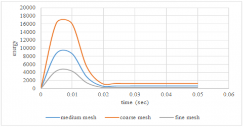
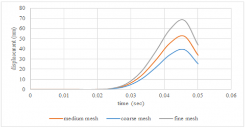
5.5 Meshing and meshing sensitivity analysis
In this section, meshing and sensitivity analysis of meshing are investigated. Three types of meshing are used, fine, medium and coarse, and the energy caused by the explosion and deformations for the explosion and the position of the middle layer are checked as displayed in Figures 53-55.
Figure 53. Model with coarse, medium and fine mesh
Figure 54. Time energy curves based on different meshing
Figure 55. Time displacement curves based on different meshing
The results of the analysis showed that the use of coarse meshing, which leads to the hard behavior of the thermomodel, compared to the behavior of the model with medium meshing, leads to an increase in maximum energy up to about 1.9 times (almost twice) and a decrease in displacement by 25%. becomes Also, the use of fine meshing leads to soft behavior of the model, which reduces the maximum energy by about 50%, but the displacement increases by about 30%.
5.6 Evaluation of excavation vulnerability against blast load
In order to evaluate the vulnerability of excavation against of the blast load, the process of yielding and failure progress is used, and an interval is provided for the beginning of drilling yielding locally until the final destruction of the mud. In this regard, 5 degrees are considered for submission and failure:
1) Local excavation damage without the possibility of any local collapse in parts of the pit.
2) Damage in the excavation area with the possibility of local collapse in parts of the pit.
3) The damage of a large part of the excavation along with the fall of a large part of the soil of the walls into the pit, but the pit has stable conditions.
4) Damage to all parts of the excavation along with the heavy fall of wall soil into the pit and the possibility of the overall instability of the pit.
5) Full collapse of the excavation and its instability.
These 5 ranges depend not only on the intensity of the explosion and the amount of explosive material, but also on the time of the explosion, and it is also a function of the type and resistance of the soil, the geometric conditions of the excavation, and its height and dimensions in the plan and angle of excavation, etc. Therefore, these 5 ranges are a function of the intensity and time of the explosion, and we may have all 5 ranges for one pit.
In order to evaluate the level of damage caused by the blast load, the following procedure is used for excavation:
1) Based on the software method and modeling, the pit is analyzed under the blast load and the contours of strain and shear stress caused by the blast load are extracted for the model.
2) Shear stress due to blast load with soil shear strength (in granular soils, resistance due to friction between grains and in fine-grained and sticky soil due to cohesion, and in mixed soils due to friction between grains and cohesion at the same time is) is compared.
3) Areas of the model that have shear stress greater than the shear strength of the soil have collapsed and are unstable, and other areas are evaluated based on the ratio of stress to shear strength, the higher this ratio is, the more critical the situation is. For ratios equal to one and more, there is always a drop, but for ratios less than one, the possibility of drop is ruled out and it is not a problem.
4) If the ratio of the stress caused by the explosion to the pit resistance is less than 15%, risk range 1 and between 15 and 35% risk range 2 and between 35 and 50 risk range 3 and 50 to 70% risk range 4 and finally range 70 Up to 100 indicates the danger range of 5 and pit collapse and instability as demonstrated in Table 6.
Table 6. Different ranges of pit risk and vulnerability under blast load
|
Degree of Danger |
Range of Stress Ratio |
|
Less |
Less than and equal to 15% |
|
Medium |
Between 15 and 35% |
|
High |
Between 35 and 50% |
|
Very high |
Between 50 and 70% |
|
Absolutely dangerous |
Between 70 and 100% |
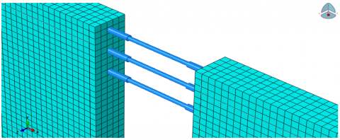
5.7 Investigating the impact of the damper on the response of the excavation under the effect of explosion
In the last part of the study, the impact of the damper on the excavation behavior against the blast load is investigated. In this regard, the number and position of the damper are two important parameters. In general, a damper is a seismic system in various structures that works during an earthquake and does not play a role in bearing static loads. The use of a damper along with structural load-bearing elements can increase the damping of structures by more than 50%. increase. The way the damper works is that absorbent systems, which are also known as energy absorbers, absorb the energy resulting from strong movements of the earth caused by loads such as earthquakes, explosions, etc. One of the characteristics of dampers is to create flexibility. Creating flexibility increases the natural cycle time of the structure. Increasing the cycle time also reduces the resonance phenomenon and reduces the acceleration in the structure. There are different types of dampers, in this study, viscoelastic dampers are used. The damper is installed around the pit bracing system, the purpose of which is to increase the plasticity and energy absorption power. Elastomeric and plastic materials are used in the production of viscoelastic dampers. The way these types of dampers work is in such a way that by changing the shear shape, it destroys the force and energy caused by forces such as earthquakes and explosions and other dynamic forces. The structure of these types of dampers is such that plastic and elastomeric materials It is placed on top of each other in multiple layers and they are compressed, and steel sheets are placed between these layers. Since the performance of these types of dampers is such that they need to change location for their operation, they must be placed in a local Installed and used in such a way that the maximum relative displacement takes place in them. Therefore, the position of this damper is considered at the place of the highest brace. In this research, the viscoelastic damper is considered and this damper is used in restraining elements. The studied parameters include damping and damping hardness. According to Figure 56, the dampers are placed at both ends of the bracing. The purpose of assessing the response of the pit includes the change of location and energy and the percentage of changes in the force of the restraining elements without and with the damper and according to the stiffness and damping of the damper, the results of which are given in Figure 57.
Figure 56. The position of the damper in the restraining elements of the pit
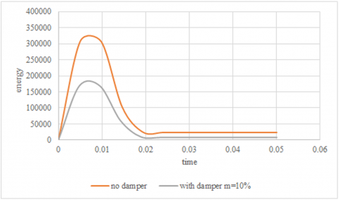
Figure 57. Comparison of the time-energy curve caused by the explosion for a pit with a width of 16 meters without and with damper
The obtained results showed that the use of a damper can reduce up to 25% of the energy caused by the explosion for the pit in question, although the amount of energy reduction is a function of the characteristics of the soil - the intensity of the explosion the height and width of the pit, as well as the hardness and damping of the damper. The case will be examined further see Figure 58.
Figure 58. Effect of damper damping changes on time energy curve
Figure 59. Comparison of time-energy curves for a pit with a width of 8 meters without and with a damper
Figure 60. Comparison of energy-time curves for a 20-meter-wide pit without and with damper
As it is known, by increasing the damping of the damper, the energy is reduced by 20%, and we have seen an increase in energy for the damping of 30%, which indicates that increasing the damping to a certain extent (depending on different parameters) leads to a decrease in energy. and for larger values, the amount of energy has not changed, and further, with a further increase, the energy damping increases. In fact, the increase in energy per damping is more due to the fact that after reaching the effective and required amount of damping in order to reduce the energy, the increase in damping has led to an increase in the plasticity of the restraints, which ultimately increases the strength of the restraints due to the restraint function in the direction of the stability of the well. found and indirectly (increasing the energy of restraints and the structural part) energy increases. Also, the results showed that increasing the stiffness of the damper by more than 15% of the conventional value (based on calculations) does not have a special effect on energy reduction as shown in Figures 59-60.
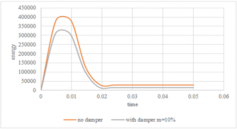
Figure 61. Comparison of pit time energy curves without and with damper for a pit with a depth of 8 meters
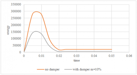
Figure 62. Comparison of pit time energy curves without and with damper for a pit with a depth of 14 meters
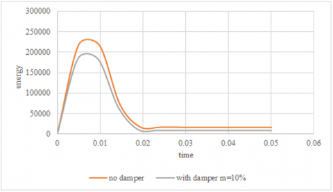
Figure 63. Comparison of pit time energy curves without and with damper for a pit with a depth of 20 meters
The results also showed that with the increase in the width of the pit, the effect of the use of the damper on the amount of energy reduction has increased. An interesting point is that the relationship between the width of the pit and the amount of energy reduction is not linear, and for pits with a width of more than 10 meters and with the increase of the width of the pit, the amount of energy reduction is non-linear and the decrease is upward. It should be noted that the cause of this is the significant increase in the ductility of the pit with the width of the pit, which means the increase in the ductility and width of the pit is also nonlinear and ascending. Further, in order to complete the results, the effect of the height of the pit is also investigated as demonstrated in Figures 61-63.
The results show that with the increase in the height of the pit, especially for pits with medium and high height (medium and deep pits), the effect of using the damper decreases in a non-linear way. This problem is especially evident for deep pits. The very high plasticity of medium and deep pits, especially with dampers, has led to a significant increase in restraining forces, which reduces the impact of the damper on the further reduction of energy for medium and deep pits.
This study investigates the behavior of RLBRB-equipped diaphragm walls under blast loads using finite element analysis in Abaqus. A parametric analysis was conducted based on five scenarios: (1) the effect of pit width (8 m, 16 m, 20 m) at a fixed depth of 14 m, (2) the effect of pit depth (8 m, 14 m, 20 m) at a fixed width of 20 m, (3) the influence of soil properties (cohesion, internal friction angle, and specific weight) on blast response, (4) the impact of explosion location (bottom, middle, and top layers of the pit), and (5) the role of soil strut dimensions in pit stability. The study employs a software-based approach to evaluate displacement, stress distribution, and energy dissipation, providing insights into optimizing excavation support systems against blast impacts. The following finding emerged:
1. Narrower pits (8 m, 16 m) exhibit 20-45% higher blast energy and increased strut forces (1.8x–4.4x) than wider pits (20m), while lateral displacement decreases by 15-25%, requiring increased wall thickness and strut plasticity for stability.
2. Pit depth influences blast response, with energy decreasing up to 14m but increasing exponentially at 20m, leading to instability and higher displacement risks without adequate bracing.
3. Soil properties significantly impact stability, as increasing internal friction angle (10°–30°) raises energy levels but reduces displacement, while higher cohesion (2x–3x) effectively lowers blast energy by 25–45%.
4. Explosion position plays a crucial role, with blasts at the pit bottom generating 8x more energy than surface blasts and middle-layer explosions causing the highest displacement and structural stress.
5. Damage evaluation is based on stress-to-resistance ratios, guiding reinforcement strategies such as cement injection, lime stabilization, shotcrete, geosynthetics, external retaining walls, and dampers to enhance blast resilience.
6. Dampers effectively reduce blast energy by up to 25%, but their efficiency decreases in deep pits due to high plasticity, requiring optimal damping design to prevent excessive structural forces.
This study analyzes the efficiency of resilient-layer buckling restrained braces (RLBRBs) in enhancing pit stability under blast loads using FEA. Future research should extend this investigation by examining soil-structure interaction under multi-phase blast loads, exploring hybrid bracing systems that integrate RLBRBs with additional dampers, and conducting experimental validation to refine numerical models for improved real-world applicability.
[1] Wang, H., Wu, C., Zhang, F., Fang, Q., Xiang, H., Li, P., Li, Z., Zhou, Y., Zhang, Y., Li, J. (2017). Experimental study of large-sized concrete filled steel tube columns under blast load. Construction and Building Materials, 134: 131-141. https://doi.org/10.1016/j.conbuildmat.2016.12.096
[2] Zhang, W., Liu, H., Zhang, W., Liu, H. (2022). Excavation failure cases and analysis. In Design of Deep Braced Excavation and Earth Retaining Systems Under Complex Built Environment: Theories and Case Studies, pp. 383-416. https://doi.org/10.1007/978-981-16-5320-9_11
[3] Houhou, M.N., Emeriault, F., Belounar, A. (2019). Three-dimensional numerical back-analysis of a monitored deep excavation retained by strutted diaphragm walls. Tunnelling and Underground Space Technology, 83: 153-164. https://doi.org/10.1016/j.tust.2018.09.013
[4] Zhang, W., Han, L., Feng, L., Ding, X., Wang, L., Chen, Z., Liu, H., Aljarmouzi, S., Sun, W. (2020). Study on seismic behaviors of a double box utility tunnel with joint connections using shaking table model tests. Soil Dynamics and Earthquake Engineering, 136: 106118. https://doi.org/10.1016/j.soildyn.2020.106118
[5] Zhang, W., Han, L., Gu, X., Wang, L., Chen, F., Liu, H. (2022). Tunneling and deep excavations in spatially variable soil and rock masses: A short review. Underground Space, 7(3): 380-407. https://doi.org/10.1016/j.undsp.2020.03.003
[6] Zhang, W.G., Han, L., Chen, Z.X., Feng, L., Ding, X., Liu, H. (2020). Model tests on seismic performance of double-box underground utility tunnel. Chinese Journal of Geotechnical Engineering, 42(1): 100-108.
[7] Lin, D.G., Chung, T.C., Phien-Wej, N. (2003). Quantitative evaluation of corner effect on deformation behavior of multi-strutted deep excavation in Bangkok subsoil. Geotechnical Engineering, 34(1): 41-57.
[8] Long, M. (2001). Database for retaining wall and ground movements due to deep excavations. Journal of Geotechnical and Geoenvironmental Engineering, 127(3): 203-224. https://doi.org/10.1061/(ASCE)1090-0241(2001)127:3(203)
[9] Moormann, C. (2004). Analysis of wall and ground movements due to deep excavations in soft soil based on a new worldwide database. Soils and Foundations, 44(1): 87-98. https://doi.org/10.3208/sandf.44.87
[10] Ou, C.Y., Hsieh, P.G., Chiou, D.C. (1993). Characteristics of ground surface settlement during excavation. Canadian Geotechnical Journal, 30(5): 758-767. https://doi.org/10.1139/t93-068
[11] Zdravkovic, L., Potts, D.M., St John, H.D. (2011). Modelling of a 3D excavation in finite element analysis. In Stiff Sedimentary Clays: Genesis and Engineering Behaviour: Géotechnique Symposium in Print 2007, pp. 319-335. https://doi.org/10.1680/ssc.41080.0028
[12] Ou, C.Y., Shiau, B.Y., Wang, I.W. (2000). Three-dimensional deformation behavior of the Taipei National Enterprise Center (TNEC) excavation case history. Canadian Geotechnical Journal, 37(2): 438-448. https://doi.org/10.1139/t00-018
[13] Guo, P., Gong, X., Wang, Y., Lin, H., Zhao, Y. (2023). Analysis of observed performance of a deep excavation straddled by shallowly buried pressurized pipelines and underneath traversed by planned tunnels. Tunnelling and Underground Space Technology, 132: 104946. https://doi.org/10.1016/j.tust.2022.104946
[14] Liu, J., Ye, J., Shen, X., Yu, J., Wu, T., Yuan, J., Ye, Q., Wang, S., He, H. (2023). In-situ monitoring and numerical analysis of deformation in deep foundation pit support: A case study in Taizhou. Applied Sciences, 13(10): 6288. https://doi.org/10.3390/app13106288
[15] Song, Z., Wu, Y., Zhang, Y., Wang, K., Tian, J., Tian, X. (2023). Deformation response of a pipeline to nearby deep foundation pit excavation: Numerical simulations and field tests. Applied Sciences, 13(11): 6597. https://doi.org/10.3390/app13116597
[16] Keshavarz Mirza Mohammadi, P., Khalilpour, S.H., Sareh, P. (2023). Simulating the response of buried structures to external blast loads: Methods, challenges, and advances. Engineering Reports, 5(6): e12607. https://doi.org/10.1002/eng2.12607
[17] Khademalrasoul, A., Shirmohammadi, A., Pakbaz, M.S., Labibzadeh, M. (2022). Seismic soft soil-structure interaction using RLBRB-equipped strut in deep excavations. Journal of Earthquake Engineering, 26(7): 3572-3600. https://doi.org/10.1080/13632469.2020.1811805
[18] Kangda, M.Z. (2022). Blast protection techniques: A review. Archives of Computational Methods in Engineering, 29(5): 3509-3529. https://doi.org/10.1007/s11831-021-09704-5
[19] Shi, J., Xu, W., Zhang, H., Ma, X., An, H. (2022). Dynamic response and failure mechanism of deep-buried tunnel with small net distance under blasting load. Buildings, 13(3): 711. https://doi.org/10.3390/buildings13030711
[20] Guan, X., Yang, N., Zhang, W., Li, M., Liu, Z., Wang, X., Zhang, S. (2022). Vibration response and failure modes analysis of the temporary support structure under blasting excavation of tunnels. Engineering Failure Analysis, 136: 106188. https://doi.org/10.1016/j.engfailanal.2022.106188
[21] Taiyari, F., Hajihassani, M., Kharghani, M. (2022). Efficiency of the evolutionary methods on the optimal design of secant pile retaining systems in a deep excavation. Neural Computing and Applications, 34(22): 20313-20325. https://doi.org/10.1007/s00521-022-07591-w
[22] Yong, W., Zhang, W., Nguyen, H., Bui, X.N., Choi, Y., Nguyen-Thoi, T., Zhou, J., Tran, T.T. (2022). Analysis and prediction of diaphragm wall deflection induced by deep braced excavations using finite element method and artificial neural network optimized by metaheuristic algorithms. Reliability Engineering & System Safety, 221: 108335. https://doi.org/10.1016/j.ress.2022.108335
[23] Zhu, B., Jiang, N., Zhou, C., Luo, X., Li, H., Chang, X., Xia, Y. (2022). Dynamic interaction of the pipe-soil subject to underground blasting excavation vibration in an urban soil-rock stratum. Tunnelling and Underground Space Technology, 129: 104700. https://doi.org/10.1016/j.tust.2022.104700
[24] Ozcelik, R., Dikiciasik, Y., Erdil, E.F. (2017). The development of the buckling restrained braces with new end restrains. Journal of Constructional Steel Research, 138: 208-220. https://doi.org/10.1016/j.jcsr.2017.07.008
[25] Tabatabaei, S.A.R., Mirghaderi, S.R., Hosseini, A. (2014). Experimental and numerical developing of reduced length buckling-restrained braces. Engineering Structures, 77: 143-160. https://doi.org/10.1016/j.engstruct.2014.07.034
[26] Chowdhury, S.S., Deb, K., Sengupta, A. (2013). Estimation of design parameters for braced excavation: Numerical study. International Journal of Geomechanics, 13(3): 234-247. https://doi.org/10.1061/(ASCE)GM.1943-5622.0000207
[27] Tong, J.Z., Guo, Y.L. (2018). Numerical investigations on elastic buckling and hysteretic behavior of steel angles assembled buckling-restrained braces. Journal of Constructional Steel Research, 144: 21-39. https://doi.org/10.1016/j.jcsr.2018.01.015
[28] Terzaghi, K., Peck, R.B., Mesri, G. (1996). Soil Mechanics in Engineering Practice. John Wiley & Sons.
[29] Clough, G.W. (1990). Construction induced movements of insitu wall, design and performance of earth retaining structure. In Specialty Conference on Design and Performance of Earth Retaining Structures, pp. 439-479.
[30] Bryson, L.S., Zapata-Medina, D.G. (2012). Method for estimating system stiffness for excavation support walls. Journal of Geotechnical and Geoenvironmental Engineering, 138(9): 1104-1115. https://doi.org/10.1061/(ASCE)GT.1943-5606.0000683
[31] Khademalrasoul, A., Shirmohammadi, A., Pakbaz, M.S., Labibzadeh, M. (2022). Seismic soft soil-structure interaction using RLBRB-equipped strut in deep excavations. Journal of Earthquake Engineering, 26(7): 3572-3600. https://doi.org/10.1080/13632469.2020.1811805
[32] Ukritchon, B., Whittle, A.J., Sloan, S.W. (2003). Undrained stability of braced excavations in clay. Journal of Geotechnical and Geoenvironmental Engineering, 129(8): 738-755. https://doi.org/10.1061/(ASCE)1090-0241(2003)129:8(738)
[33] Chakraborty, T. (2016). Analysis of hollow steel piles subjected to buried blast loading. Computers and Geotechnics, 78: 194-202. https://doi.org/10.1016/j.compgeo.2016.05.015
[34] Khademalrasoul, A., Amerikhah, H. (2022). Investigation of geomorphometric parameters to simplify water erosion modelling (a case study: Emamzadeh Watershed, Iran). Polish Journal of Soil Science, 55(1): 1-18. http://doi.org/10.17951/pjss.2022.55.1.1-18