Ali Abdulameer Al-Rammahi![]() | Rashad Raad Jawad
| Rashad Raad Jawad![]() | Ali Abdulmohsin Khamees*
| Ali Abdulmohsin Khamees*![]()
© 2025 The authors. This article is published by IIETA and is licensed under the CC BY 4.0 license (http://creativecommons.org/licenses/by/4.0/).
OPEN ACCESS
Numerous ducts and channels are installed during the development of a reinforced concrete building to provide sanitary conditions and to facilitate the supply of vital services like electricity, internet, computer networks, and air ventilation. Consequently, it is unusual for these services to need the drilling of holes in the building’s structural elements. A thorough numerical program was executed to investigate the structural behavior of reinforced concrete beams having apertures. The effect of increasing the number of opening ribs on the behavior of reinforced concrete beams concerning the presence of openings in flexural and shear zones was investigated using eleven specimens. The specimens were also designed to control flexure failure prior to shear. In addition, the experimental data collected by the prior researchers were used to calibrate and validate the finite element model. The model agrees with the correct data with respect to the load-deflection response, failure mechanism, and ultimate load capacity. The numerical analysis was shown to be correct by comparing it with experimental data. The results showed that for all the models considered, the highest difference ratio based on the ultimate load was less than 15%. In comparison to apertures in the shape of triangles, squares, pentagons, and hexagons, the numerical data showed that elliptical holes reduced the load capacity of the beam the least. Where, its reduction was 5.4%, much lower than that of the beam devoid of an aperture, which was 8.9%. The pentagon apertures performed poorly compared to the hexagon openings, which showed a 4% improvement in flexural load capacity and a 6% increase in shear zone load capacity.
concrete beam, opening shape effects, shear, flexural, numerical investigation
A range of metrics and shapes are often found in beam apertures. Shear stresses are more common in these structural components because of their closeness to the supports. Environmental services that reduce building heights and concrete beam weight are commonplace in practice. This necessitates making these services easily accessible. It is recommended to cut holes in the concrete beams so that the chords may receive the concrete area needed to form the ultimate compression block while bending, as well as the depth needed to reinforce against shear loads effectively [1]. Ample ceiling headroom is usually unnecessary when holes are cut in concrete beams to accommodate utility ducts like those for air conditioning, electricity, or a computer network.
Conversely, these holes might severely compromise the strength of the concrete framework. Hence, many investigations looked at how holes affect the strength behavior of reinforced concrete beams. Testing on a traditional joist floor with both round and square holes in the web, Hanson [2] found that the reduction in strength was unaffected by an aperture’s proximity to the support. Floruţ et al. [3] conducted a battery of tests on reinforced concrete slabs (RCS) with cut-out apertures to study the impact of the openings on the concrete’s reactivity. Mohamed et al. [4] predicted the behavior of web-holed reinforced concrete deep beams (RCDP) using the finite element method. Siao and Yap [5] state that the beams break before their time because the compression chord is suddenly cracked diagonally. This happens when the members nearest the opening (the chord members) do not get any additional strengthening. The influence of the aperture type on the behavior and strength of reinforced concrete (RC) beams was assessed by Hafiz et al. [6] using numerical simulations. In their experimental program, Morsy and Barima [7] examined the performance of reinforced and unstrengthened RC beams with apertures.
In comparison to square and rectangular apertures, circular apertures reduced the load capacity of the beam the least, as seen in the experimental results. The reason for this is that each of the opening shapes has the same area. For their study on how size affects RC beam behavior, Godat et al. [8] used computational and experimental tools. Abdalla et al. [9] employed sheets of fiber-reinforced polymer (FRP) to increase the aperture size. The study is limited in breadth because of the challenges in procuring the materials and the right conditions to conduct the experiments. Materials that meet specific size and component requirements are also scarce [10]. An investigation into the effect of opening on the behavior of concrete buildings and walls under compressive pressures was recently carried out by Popescu et al. [11].
Complex physical problems, such as beams with differently shaped apertures, may be solved using the finite element method. Simply said, concrete is a material whose loading behavior is definitely not linear. The numerical behavior of a reinforced concrete structural beam with triangular, square, pentagon, hexagon, and elliptical apertures is examined in this work via the use of nonlinear analysis coded in the ABACUS finite element model. Static loads are applied to the beam. In what follows, we will describe and analyze the finite element models of beams with and without apertures. The load-displacement curve, failure type, and failure load amount were considered after the models were evaluated.
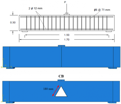
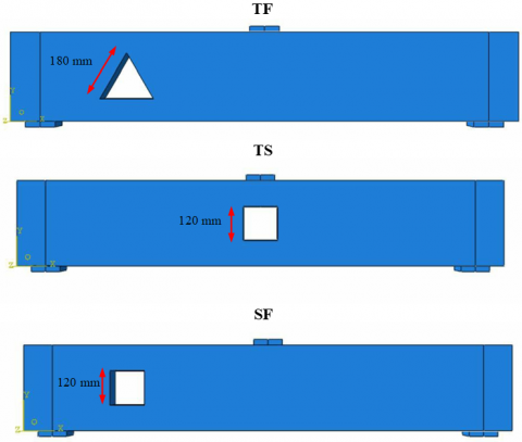
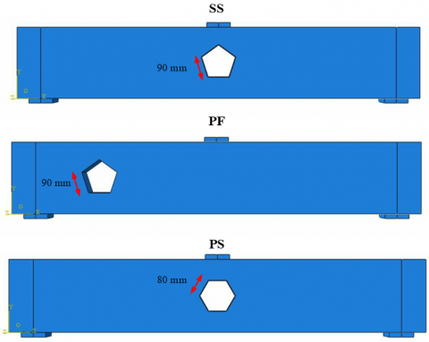
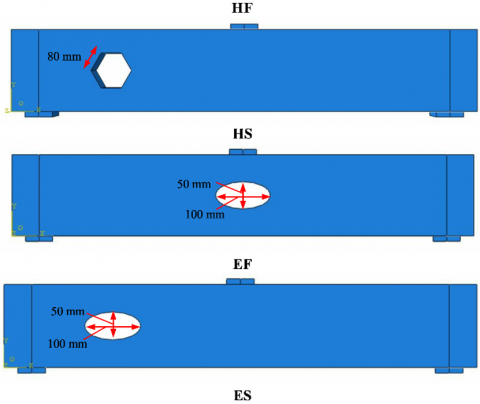
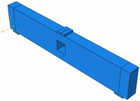
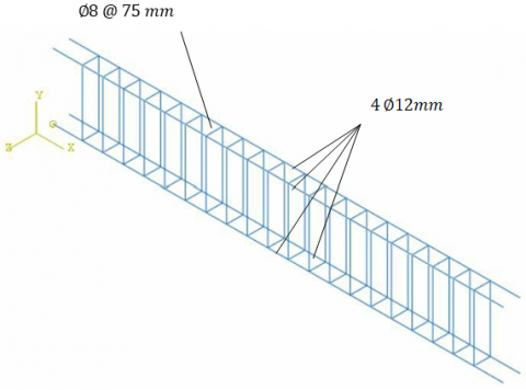
Figure 1 shows the considered design of the reinforced concrete beam. Various post apertures, such as triangles, squares, pentagons, hexagons, and ellipses, were examined with the 120 × 300 × 1700 mm beam, among others. All of the forms had identical opening areas, which were about 14400 mm2; the tringle opening had a side of 55 mm, the square hole was 120 × 120 mm, the pentagon opening was 55 mm, and the hexagonal opening was 45 mm. Both the primary and minor axes of the ellipse were determined by their relative lengths. As an added bonus, the beam’s steel reinforcement met the following specifications:
-Top and bottom rebar: 2ø12 mm
- Stirrup: ø8@ 75 mm c/c
In this context, the first letter of the code, “F,” is used to describe a beam with a hole in the flexure zone, while the letter “S” is used to describe the kind of opening in the shear zone. The goal of removing these terms from the beam descriptions was to make them more easily identifiable. In this system, the tringle opening is associated with the second letter of the alphabet; the square opening is symbolized by the letter “S,” the pentagon opening by the letter “P,” the hexagon opening by the letter “H,” and the elliptical openness by the letter “E.”
Figure 1. Geometry and dimension of the beam and its opening
A 3D finite element model was developed using ABAQUS/CAE version 6.12-3. Figure 2 illustrates the three elements used in constructing the model: a reinforced concrete beam, two base plates equipped with pins and rollers, and a top plate. A ten-node quadratic tetrahedron was used to model the concrete beam and fixation plates, enhancing the visibility of surface stress. A fundamental structure is used to support the reinforced beam in the simulation. The load applied to the top plate remained invariant. Static Riks, as an analytical approach, considers any significant outliers that arise throughout the simulation. The models’ dimension is illustrated in Table 1.
Table 1. Models’ dimensions
|
Specimen Designations |
Total Span (mm) |
Total Height (mm) |
Hole Shape |
Notes |
|
CB |
1700 |
300 |
Non |
Reference model without hole. |
|
TF |
1700 |
300 |
Triangle |
Triangle hole with a total area of 14,400 mm2 in flexure zone. |
|
TS |
1700 |
300 |
Triangle |
Triangle hole with a total area of 14,400 mm2 in shear zone. |
|
SF |
1700 |
300 |
Square |
A square hole with a total area of 14,400 mm2 in the flexure zone. |
|
SS |
1700 |
300 |
Square |
A square hole with a total area of 14,400 mm2 in shear zone. |
|
PF |
1700 |
300 |
Pentagon |
Pentagon hole with a total area of 14,400 mm2 in the flexure zone. |
|
PS |
1700 |
300 |
Pentagon |
Pentagon hole with a total area of 14,400 mm2 in shear zone. |
|
HF |
1700 |
300 |
Hexagon |
Hexagon hole with a total area of 14,400 mm2 in flexure zone. |
|
HS |
1700 |
300 |
Hexagon |
Hexagon hole with a total area of 14,400 mm2 in shear zone. |
|
EF |
1700 |
300 |
Ellipse |
Ellipse hole with a total area of 14,400 mm2 in flexure zone. |
|
ES |
1700 |
300 |
Ellipse |
Ellipse hole with a total area of 14,400 mm2 in shear zone. |
(a)
(b)
Figure 2. Reinforced concrete beam FE model
3.1 Materials properties and meshing
In this study, the model for the ABAQUS program is represented by a drawing. Because of the difficulty of the concrete beam specimen’s details, the models were drawn using the AutoCAD 3D program; then, model graphics were exported to the ABAQUS program. The graphics are saved as 3D deformable parts when imported into the ABAQUS program.
The characteristics of the designated materials must align perfectly with those of the specimens under scrutiny in order to get similar results.
Concrete Damaged Plasticity (SDP) is used for modelling the concrete, as suggested by earlier research [12]. The compressive strength of the concrete, which was determined to be 29.84 GPa for 40 MPa concrete, was shown to have a significant role in determining the concrete’s flexibility. The Poisson’s ratio for concrete, across all varieties, was found to be 0.2.
A combination of an elastoplastic and strain-hardening model allows for a very accurate reproduction of concrete’s compressive behavior. This model’s internal representation of compressive stress values is based on an example of plastic strain expression. Once the maximal stress had been experienced, the stress-strain curve was defined farther into the strain-softening regime. Using the stress-strain relationship given by Desay and Kreshnan [13], researchers were able to model the compressive behavior of concrete.
The tension stiffening is shown with the help of strain and stress data. The relationship between stress and strain is based on the assumption that tensile stress increases linearly with increasing tensile strain until the concrete breaks. After a fracture has formed in concrete, the material’s tensile strength gradually drops until it is almost nothing. When the concrete approaches zero, the effect ends [14-20].
In order to predict the reinforcing steel bars’ behavior, we used a classical model that described the plastic and elastic parts. A steel rebar with a diameter of 8 or 12 mm has a modulus of elasticity of 195 gigapascals. Furthermore, it was found that the Poisson’s ratio was exactly 0.3 for all of the steel compositions.
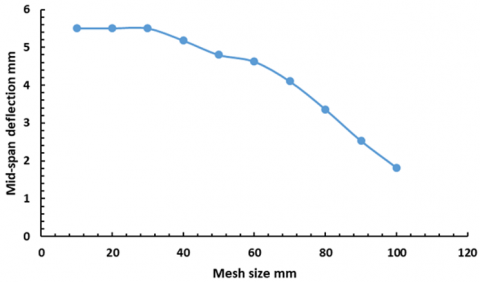
In order to get the results to converge, it is crucial to choose the suitable element sizes. This study changed the number of pieces to acquire the same behavior for both the models and the evaluated specimens regarding failure mechanism and failure mid-span deflection. Based on the results of the convergence study, it was decided that the reinforced concrete beam model needed to have a sufficient mesh density. In practice, this is best achieved by increasing the mesh size, which hardly affects the results [21-23]. Figure 3 shows the result of reducing the mesh size of the beam from 100 to 10 millimeters. Thirty millimeters was the ideal beam mesh dimension. The previously discernible rise in deflection at the model’s core is now tiny to the point of being insignificant. The size 30 mm was chosen for this very purpose. It was observed that the mid-span deflection of every beam remained constant throughout the length of the beam.
Figure 3. Convergent study for mish size
3.2 Calibration of models
The findings of earlier investigators in the load-deflection action, ultimate load, and failure mode were utilized in order to calibrate the finite-element model [7]. Other researchers’ discoveries were also utilized. The findings of the experimental tests and the findings of the FE tests were discovered to be in agreement with one another after a series of tests were conducted. This was realized due to the fact that the specimens displayed the same deflection response. A failure mechanism that was the same as the one discovered in the trials was also discovered in the FE simulation that matched the trials themselves. An instance of flexural failure in the beam was utilized for testing and simulation purposes. The maximum load of the calibrated specimens was also compared to the load that was experimentally measured by the researchers who came before and came before them. This was done in order to ensure that the results were accurate. It was discovered that the FE model was more conservative than the experiment. This was due to the fact that the relative difference between the experimental and FE ultimate load was less than fifteen percent.
The validation of the calibrated models was accomplished via the use of the load-deflection reaction as well as the ultimate load capacity. One thing that was observed was that the loading stages had a degree of agreement that was adequate. Other researchers validated the validity of the model once it was shown that all of the models that had been previously represented conformed to the standards.
4.1 Load-displacement response
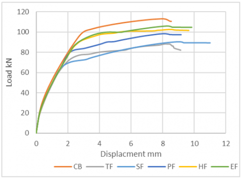
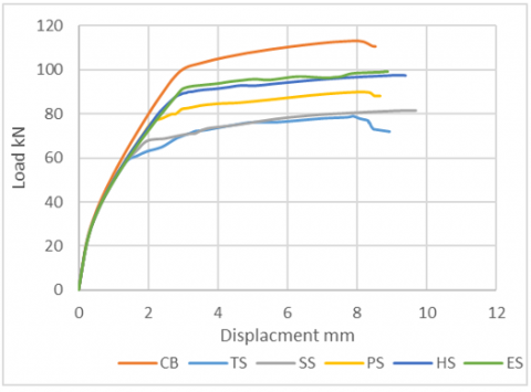
Analyzing the model allows one to deconstruct the load-displacement reaction into three distinct phases. In the initial stage, the relationship between applied force and deflection being a direct line of proportionality. The beam enters an elastoplastic phase when its shape changes in response to an increase in load, as seen by the load-displacement curve. Then, by changing the load-displacement curve’s slope, the specimens’ plastic phase is quickly increased. This is because even a slight change in charge causes a noticeable increase in displacement. Figure 4 shows the load-deflection curves for beams that have apertures. The existence of an opening reduced the stiffness of the beams, as seen by these graphs, as compared to the control beam. Whenever there are holes in the web, the beam’s behavior changes. The models lose their ductility as a result of a decrease in the elastic stage and an increase in deflection.
Figure 4. Load displacement curves for models
4.2 Failure load and failure deflection
To ascertain the ultimate strength, several models were simulated with various hole configurations. The objective was to investigate additional elements influencing beam behavior. The models using apertures were examined for geometric forms including triangles, squares, pentagons, hexagons, and ellipses. In all instances, the hole area had to measure precisely 14,400 square millimeters. The study's results are shown in Table 2.
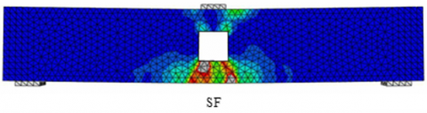
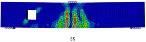
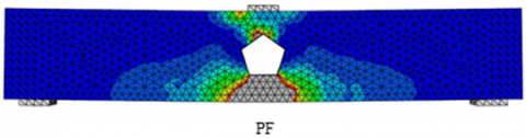
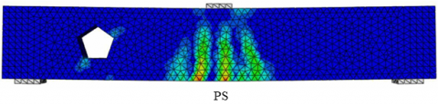
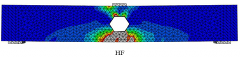
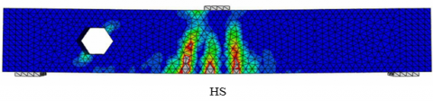
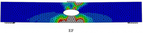
Typically, cutting a hole in a beam drastically lowered its load capacity. When the hole was situated in the shear zone instead of the flexural zone, this became very evident. Figure 5 shows that in the flexure and shear zones, the elliptical aperture performed better than the other opening forms. Additionally, its reduction was 5.4%, much lower than that of the beam devoid of an aperture, which was 8.9%. This stood in contrast to the control beam. Due to the lack of elliptical edges, the stress is not concentrated on the elliptical opening. This allows the load to be distributed efficiently throughout the aperture surface, delaying failure. The pentagon apertures performed poorly compared to the hexagon openings, which showed a 4% improvement in flexural load capacity and a 6% increase in shear zone load capacity. The load capacity loss for the flexural zone was 8.1%, and for the shear zone, it was 10.8% compared to the beams without apertures. The load capacity in the flexure zone of the triangle opening was found to be 21% lower than the control specimen, while in the shear zone, it was 28.8% lower.
Similarly, it was 18.9% lower in the square opening, and in both cases, it was 27% lower. It is highly advised to use the flexural zone instead of the shear zone when making an opening quickly, which is essential. The shear zone experiences a substantially more significant decrease than the flexural zone, which is why. Furthermore, while a square or triangle with the same cross-section area is acceptable, an ellipse or hexagon is far better, and neither of these shapes is recommended for an aperture.
Table 2. Results of the study
|
Specimen Designations |
Ultimate Load (kN) |
Failure Deflection (mm) |
|
CB |
111 |
8.54 |
|
TF |
87 |
9.15 |
|
TS |
79 |
8.94 |
|
SF |
90 |
11.00 |
|
SS |
81 |
9.62 |
|
PF |
98 |
9.17 |
|
PS |
91 |
8.66 |
|
HF |
102 |
9.65 |
|
HS |
97 |
9.04 |
|
EF |
105 |
9.83 |
|
ES |
99 |
8.89 |
4.3 Models’ failure mode
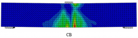
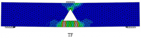
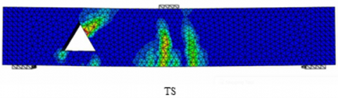
The most common way that beams break is due to diagonal cracks that begin at the aperture’s corner and spread to the area of application and the support, leading to an unusually rapid collapse. Although the failure mechanism for both the flexure zone and the shear zone was the same as shown in Figure 5, the capacity of the beam with an elliptical aperture was often higher than that of the beam with a triangular, square, pentagonal, or hexagonal opening. Early diagonal cracks have developed at the aperture corner due to the concentration of stress. Since the tension is concentrated, this conduct occurs.
Figure 5. Failure mode of FE models
In the scope of this study, based on results derived from the finite-element simulation with an ABACUS method for concrete beam with holes models subject to one concentrated load, the following conclusions could be drawn:
1. The reinforced concrete beam with apertures may be modeled using the three-dimensional finite element model used in this study. It also shows much agreement when it comes to the failure mechanism, ultimate load capacity, and the reaction to load deflection. The numerical analysis was found to have a high level of validity, as illustrated by the fact that, when compared to the experimental data, the maximum difference ratio based on the ultimate load for all of the models was less than 15%.
2. In most cases, the load capacity of a beam is drastically reduced when a hole is cut into it. This becomes particularly evident when the aperture is situated in the shear zone instead of the flexural zone. Thus, it is recommended that holes be built in the flexural zone wherever necessary.
3. In both the shear and flexure zones, the elliptical opening outperformed the other types. After that came the pentagon, hexagon, and square holes, and last but not least was the triangle hole, which performed the worst.
4. Even though the shear zone aperture is much larger than the flexural zone aperture, the load capacity has shrunk.
5. It was found that the elliptical aperture was the best form for a hole since it showed the slightest degree of decline in ultimate load.
6. There is a gap in the experimental investigations concerning the effect of repairing on reinforced concrete shallow beams damaged due to openings, so it is recommended to conduct related research.
7. Moreover, future research studies have to discuss the structural behavior of reinforced concrete beams with different types of openings subjected to reverse cyclic loadings.
The researchers thank all their colleagues in the scientific research.
[1] Amiri, S., Masoudnia, R. (2011). Investigation of the opening effects on the behaviour of concrete beams without additional reinforcement in opening region using FEM method. Australian Journal of Basic and Applied Sciences, 5(5): 617-627. https://doi.org/10.13140/RG.2.1.2108.1041
[2] Hanson, J.M. (1969). Square openings in webs of continuous joists. Portland Cement Assoc R & D Lab Bull. https://trid.trb.org/View/98472.
[3] Floruţ, S.C., Sas, G., Popescu, C., Stoian, V. (2014). Tests on reinforced concrete slabs with cut-out openings strengthened with fibre-reinforced polymers. Composites Part B: Engineering, 66: 484-493. https://doi.org/10.1016/j.compositesb.2014.06.008
[4] Mohamed, A.R., Shoukry, M.S., Saeed, J.M. (2014). Prediction of the behavior of reinforced concrete deep beams with web openings using the finite element method. Alexandria Engineering Journal, 53(2): 329-339. https://doi.org/10.1016/j.aej.2014.03.001
[5] Siao, W.B., Yap, S.F. (1990). Ultimate behaviour of unstrengthen large openings made in existing concrete beams. Journal of the Institution of Engineers, 30(3): 51-57.
[6] Hafiz, R.B., Ahmed, S., Barua, S., Chowdhury, S.R. (2014). Effects of opening on the behavior of reinforced concrete beam. Journal of Mechanical and Civil Engineering, 11(2): 52-61. https://doi.org/10.9790/1684-11275261
[7] Morsy, A.M., Barima, A.M. (2019). Behavior of R.C. beams with openings using different strengthening techniques. International Journal of Sciences: Basic and Applied Research, 46(1): 195-219. https://www.gssrr.org/index.php/JournalOfBasicAndApplied/article/view/10043.
[8] Godat, A., Qu, Z., Lu, X.Z., Labossiere, P., Ye, L.P., Neale, K.W. (2010). Size effects for reinforced concrete beams strengthened in shear with CFRP strips. Journal of Composites for Construction, 14(3): 260-271. https://doi.org/10.1061/(ASCE)CC.1943-5614.0000072
[9] Abdalla, H.A., Torkey, A.M., Haggag, H.A., Abu-Amira, A.F. (2003). Design against cracking at openings in reinforced concrete beams strengthened with composite sheets. Composite Structures, 60(2): 197-204. https://doi.org/10.1016/S0263-8223(02)00305-7
[10] Amin, H.M., Agarwal, V.C., Aziz, O.Q. (2013). Effect of opening size and location on the shear strength behavior of RC deep beams without web reinforcement. International Journal of Innovative Technology and Exploring Engineering, 3(7): 28-30. https://doi.org/10.4334/JKCI.2003.15.5.697
[11] Popescu, C., Sas, G., Blanksvärd, T., Täljsten, B. (2015). Concrete walls weakened by openings as compression members: A review. Engineering Structures, 89: 172-190. https://doi.org/10.1016/j.engstruct.2015.02.006
[12] Boulbes, R.J. (2020). Troubleshooting finite-element modeling with Abaqus: With application in structural engineering analysis. First. Springer. https://doi.org/10.1007/978-3-030-26740-7
[13] Desayi, P., Krishnan, S. (1964). Equation for the stress-strain curve of concrete. Journal Proceedings, 61(3): 345-350. https://doi.org/10.14359/7785
[14] SIMULA CO. (2017). Abaqus/CAE user’s manual. SIMULIA Worldwide. https://classes.engineering.wustl.edu/2009/spring/mase5513/abaqus/docs/v6.6/books/usi/default.htm.
[15] El-Maaddawy, T., El-Arises, B. (2012). Behavior of concrete beams with short shear span and web opening strengthened in shear with CFRP composites. Journal of Composites for Construction, 28(2): 47-59. https://doi.org/10.1061/(ASCE)CC.1943-5614.0000237
[16] Mansur, M. (1998). Effect of openings on the behavior and strength of R/C beams in shear. Cement and Concrete Composites, 20(6): 477-486. https://doi.org/10.1016/S0958-9465(98)00030-4
[17] Mansur, M., Tan, K., Wei, W. (1999). Effects of creating an opening in existing beam. ACI Structural Journal, 96(6): 899-906. https://doi.org/10.14359/785
[18] Ashour, A., Rishi, G. (2000). Tests of reinforced concrete continuous deep beams with web openings. ACI Structural Journal, 97(3): 418-426. https://doi.org/10.14359/4636
[19] Tan, K., Mansur, M., Wei, W. (2001). Design of reinforced concrete beams with circular openings. ACI Structural Journal, 98(3): 407-415. https://doi.org/10.14359/10229
[20] Bengi, A., Ilker, K., Sabahattin, A., Yusuf, E. (2013). Flexural behavior of RC beams with regular square or circular web openings. Engineering Structures, 56: 2165-2174. https://doi.org/10.1016/j.engstruct.2013.08.043
[21] Mansur, M.A., Lee, Y.F., Tan, K.H., Lee, S.L. (1991). Tests on RC continuous beams with openings. Journal of Structural Engineering ASCE, 117(1): 1593-1606. https://doi.org/10.1061/(ASCE)0733-9445(1991)117:6(1593)
[22] Al-Sheikh, S. A. (2014). Flexural behavior of RC beams with opening. Concrete Research Letters, 5(2): 812-824. https://doi.org/10.20528/cjcrl
[23] Tan, K.H., Mansur, M.A. (1996). Design procedure for reinforced concrete beams with large web openings. ACI Structural Journal, 93: 404-411. https://doi.org/10.14359/9699