Amnart Boonloi![]() | Withada Jedsadaratanachai*
| Withada Jedsadaratanachai*![]()
© 2025 The authors. This article is published by IIETA and is licensed under the CC BY 4.0 license (http://creativecommons.org/licenses/by/4.0/).
OPEN ACCESS
This study employs numerical modeling using the finite volume method to analyze airflow and thermal structures when vortex flow (VTF) generators are installed in heat exchanger square ducts (HX-SD). The VTF generator used in this study is the X-V baffle (XVB), which is designed to enhance heat transfer rates. The XVB is an evolution of the V-baffle, a type of VTF generator known for its efficiency in improving heat transfer. It features an X-shaped structure (considered in the cross-sectional (CS) plane, y-z plane) to further optimize the design. The present research investigates the effects of XVB thickness, represented by the thickness ratio (b) to the HX-SD height (H) or hydraulic diameter (Dh) (b/H), with B-R values ranging from 0.05 to 0.20. Additionally, three XVB configurations (Types A, B, and C) are examined, along with two airflow directions: AFD-VD (airflow direction – V-Downstream) and AFD-VU (airflow direction – V-Upstream). The investigation focuses on turbulent flow conditions, analyzing air velocity within a Reynolds number range of Re = 3,000 to 16,000. The results indicate that VTF is generated throughout the HX-SD due to the pressure difference caused by flow obstruction from the XVB in all cases examined. By enhancing air mixing and disrupting the thermal boundary layer (Th-BL), the induced VTF significantly increases the heat transfer rate. The maximum observed increase in heat transfer was 7.95 times higher than that of a smooth, empty duct.
computational fluid dynamics, passive method, XVB, thermal enhancement factor
Given the current global energy demand, there has been a significant push toward developing and researching sustainable energy usage by both the public and private sectors. In engineering, the development of high-performance and fully optimized equipment is another approach to achieving effective energy management and sustainable energy development. This is especially true for devices or systems that handle relatively large amounts or rates of energy, such as heat exchangers. The development of heat exchangers has garnered significant attention from research organizations. The main objectives of improving heat exchangers include increasing heat transfer rates and heat exchanger performance, while also reducing their size. The augmentation of heat transfer rates in heat exchangers can be separated into two main approaches: 1. Active Techniques and 2. Passive Techniques. Both methods are widely used in the industrial development of heat exchangers. Active techniques increase heat transfer rates by utilizing external forces applied to the system. An example of this is the use of vibrations to enhance the heat transfer coefficient in the heat transfer system. In contrast, passive techniques rise the heat transfer rate without the need for external forces. Instead, they rely on internal system behaviors to improve heat transfer. Examples include obstructing part of the flow within the heat exchanger using small components to induce swirl flow or modifying the properties of the working fluid by adding nanomaterials. Since active techniques require external energy input, which can significantly increase energy costs, this research focuses on studying heat transfer enhancement using passive techniques. Passive methods have minimal impact on energy costs and operations, making them more cost-effective. Specifically, the research emphasizes techniques that obstruct flow using small components to induce turbulence and improve thermal efficiency without the requirement for external power.
As mentioned earlier, the small components used to partially obstruct the flow and induce VTF in the process of enhancing heat transfer through passive techniques are referred to as vortex inducer, generators, turbulators, or vortex producers. These terms are used interchangeably to describe devices that create turbulence, thereby enhancing heat transfer efficiency without requiring external energy input. Vortex generators have been developed in various shapes, arrangements, and sizes, depending on the specific application of the heat transfer system. These variations are designed to optimize heat transfer performance by inducing VTF patterns that disrupt the boundary layer and improve mixing within the fluid. Design choices such as the shape of the vortex generator (e.g., ribbed, winglet, or fin-type), the spacing between them, and their size relative to the flow area are tailored to specific heat exchanger configurations and operating conditions. The goal is to achieve the best possible thermal performance while minimizing pressure drop.
Several research groups are focused on studying and developing heat exchange systems by installing vortex generators/turbulators/vortex producers to increase the heat transfer ability. Examples include:
Mukhlif and Abed [1] conducted a study on the hydrothermal efficiency/performance within a T-channel tested section with V-broken ribs (staggered arrangement) for laminar fluid flow within the Reynolds number range of 50 to 250, using numerical methods. The study looked into how the flow and heat transfer performance in the tested channels were affected by rib angles, the pitch-to-outlet-channel width ratio, the length-to-outlet-channel width ratio, the height-to-outlet-channel height ratio, and the staggered inclined rib arrangements. They found that the performance enhancement criterion reached a maximum value of 2.42, which was observed in the case of the backward V-broken rib configuration. The fluid flow pattern and thermal profile in thermal system (gas turbine blade tested-sections) with V-rib-dimple combined vortex producers (flow attack angle of 45° V-profile rib and broken V-rib with spherical dimple constructions) were studied by Kumar and Pathak [2]. The thermo-hydraulic effect of dimple depth and rib height on the fluid flow pattern and thermal profile was taken into account. They pointed out that the use of the compound structure affects the longitudinal VTF as well as the main VTF structure. They stated that in the instance of a 45° V-profile rib vortex turbulator with a height of 1.5 mm and a spherical dimple structure of 4 mm depth, the heat transfer enhancement rate reached a maximum value of 2.46 times in comparison to a smooth, empty tube. The study also found that for the case with a 1 mm high V-rib vortex turbulator and a spherical dimple structure of 2 mm depth, the thermo-hydraulic performance factor reached a maximum value of 1.205. Sutar et al. [3] conducted a simulation on a solar air heater using parabolic rib turbulators on the absorber plate within the Reynolds number range of 3,400 to 20,000, with a rib pitch ratio ranging from 6.60 to 20. The study found that a rib pitch ratio of 16.66 resulted in the maximum thermal enhancement ratio of 2.14. Hegde et al. [4] studied the influence of various V-pattern rib configurations in a rectangular duct solar air heater, analyzing both energy and exergy efficiency. They found that the discrete multi-V-rib configuration with staggered arrangement provided the highest thermal efficiency of 76.63% when considered at a Reynolds number of 21,000. Liu et al. [5] studied the enhancement of thermal ability and fluid flow pattern of microencapsulated phase change slurry (MPCS) in microchannel tested sections with various rib patterns. This research provides an important direction for the future development of microchannels. The performance of 5 wt% MPCS in a tested section (staggered pin-fin microchannel) increased by up to 26% compared to the reference tested section (a straight rib microchannel). Wang et al. [6] presented the development of thermal potential using wavy ribs with different cross-sectional (CS) shapes. They found that the heat transfer rate for large rib heights of the isosceles triangular and isosceles trapezoidal CS wavy ribs increased by 73.29% and 185.31%, respectively. Majmader and Hasan [7] presented the influence of bidirectional rib vortex turbulators within turbulence flow and heat transfer ability for a two-pass tested-channel of turbine blade internal cooling under the Reynolds number range of 10,000 to 50,000. They indicated that the bidirectional ribbed channel provided a 69% higher thermal performance compared to horizontal-only ribs. Additionally, they concluded that the overall thermohydraulic performance reached a maximum value of 1.38 in the studied range. Chhaparwal et al. [8] offered the enhancement of the solar air heater's performance by adding circular detached ribs, studying both experimental and numerical models. The study was conducted under the Reynolds number range of 3,000 to 15,000, focusing on parameters influencing flow and thermal structure such as clearance ratio, and relative longitudinal pitch ratio. Wang et al. [9] presented the use of fan-shaped grooves and triangular truncated ribs to alter the flow structure and enhance the heat transfer rate in a microchannel heat sink. They analyzed the flow within the Reynolds number range of 132.66 to 928.63. They concluded that flow disturbance and the perturbed thermal boundary layer were key reasons in increasing the potentiality of heat transfer. Fu et al. [10] examined the enhancement of heat transfer rate and system performance in impingement cooling using W-shaped micro-ribs, employing numerical methods for their analysis. They demonstrated that the heat transfer rate increased by as much as 39.7% to 48.9% compared to a smooth surface. Wang et al. [11] employed non-uniform wavy rib turbulators to enhance the thermal performance of the turbine blade cooling channel. They demonstrated that the Nusselt number increased by 22.6%. Using computational techniques to examine the problem, Prasad et al. [12] used offset transverse ribs positioned close to the absorber plate to improve a solar air heater's performance. From their research, they found that the Nusselt number enhancement ratio was 1.52, while the best system performance in the terms of thermal enhancement factor was 1.042. Jia et al. [13] analyzed flow boiling characteristics in microchannels with trapezoidal ribs installed on the walls of heat exchanger tubes. They examined the effects of mass flux, heat flux, and exit vapor quality on flow behavior and heat transfer coefficients in the tested tubes. They concluded that flow instability was less severe at higher mass and heat fluxes due to more uniform bubble size and distribution. Boonloi and Jedsadaratanachai [14] presented a numerical study on the fluid flow pattern and thermal characteristics in square CS tubes with X-V modified rib vortex producers to enhance thermal performance. They investigated parameters affecting flow pattern changes and heat transfer pattern, including the structure of the X-V rib, flow obstruction ratio, and rib arrangement, considering laminar fluid flow with Reynolds numbers varying from 100 to 2000 (considering at the inlet condition). They concluded that a key factor affecting heat transfer ability was the disturbed thermal boundary layer. Additionally, enhancing the flow blending quality was another significant factor influencing the heat transfer ability. The highest heat exchanger performance in the terms of thermal enhancement factor observed in the study was 3.48. Hu et al. [15] enhanced the thermal performance of microchannels by using various rib configurations through topology optimization. They showed that variations in the flow structure and the rate of heat transfer are greatly influenced by the optimum rib size and shape. Tamang et al. [16] presented the selection of rib turbulators to improve the thermo-hydraulic efficiency of heat exchanger tubes. They employed V-shaped ribs to increase the heat transfer coefficient. They found that, during the study, the Nusselt number increased by 45.07%, while the thermal performance factor increased by 88.57%. Xu et al. [17] presented a study on the thermal efficiency and fluid flow behavior of supercritical carbon dioxide in a cooling channel with mini-rib roughness to enhance the heat transfer rate. They concluded that the overall thermal performance factor reached a maximum value of 1.43. Ahmed and Tanda [18] studied the laminar heat transfer of unforced convection for vertical rib-roughened surfaces, employing both experimental tests and numerical modeling. Yan et al. [19] enhanced the heat transfer rate in the return channel by using ribs to induce VTF, thereby increasing the heat transfer coefficient. They studied the flow in the Reynolds number varying from 5,000 to 15,000. They came to the conclusion that adding ribs improved the heat exchanger's thermal performance because the ribbed walls increased the Nusselt number by 5.4% to 10.4%. Li et al. [20] conducted a numerical study on the thermal efficiency of a microchannel heat sink inserted with slant rib vortex producers and quatrefoil rib-elliptical groove combined structures. The results of their study demonstrated that using this method to enhance thermal performance led to a 131% increase in the heat transfer rate. Additionally, they concluded that the performance evaluation criterion reached a maximum value of 1.179. Shanmugam and Park [21] presented the changes in flow and thermal structure in a cooling tested system with the installation of arc rib vortex producers. They found that the installation of the arc rib improved the thermal performance by 1.95 and 1.384 times compared to the V-rib and cylindrical rib, respectively. They also observed that the installation of the arc rib affected the thermal boundary layer, which was directly related to the increase in heat transfer rate in the tested tubes. Zheng et al. [22] studied the changes in thermo-hydraulic performance of rectangular tested channels with the addition of hierarchical rib vortex producers. They demonstrated that, considering the similar pumping force, the thermal performance increased by 10% for the hierarchical scheme and by 21.15% for the V-rib scheme. Zhu et al. [23] presented a numerical investigation on the fluid flow behavior and thermo-hydraulic performance of a new symmetric sinusoidal wavy microchannel heat sink with the addition of turbulators (rectangular rib prisms) in the test section to enhance thermal performance. Their study revealed that the Nusselt number ratio was 4.16, and the overall performance factor reached a maximum value of 1.88 at a Reynolds number of 800.
In addition, the research team has summarized the advantages and disadvantages of certain types of vortex generators in heat exchanger tubes with different CS shapes, based on previous studies conducted by the team. The research team found that installing vortex generators on the surface of heat exchanger tubes provides better thermal performance than installing them at the center of the tubes [24]. This is because vortex generators installed on the tube surface offer better heat transfer rates and lower friction loss compared to those installed at the center. However, when the research team developed vortex generators for real experimental setups, they discovered that surface installation was relatively challenging, especially for circular CS tubes. This difficulty often led to small gaps between the surface of the heat exchanger tube and the edges of the vortex generators. These gaps could either contribute to enhancing heat transfer or reduce the strength of the fluid stream. Similarly, for tubes with rectangular CS, installing vortex generators on the square channel/duct surface provides better thermal performance than installing them at the center of the square channel/duct [25]. However, in real experimental setups, small gaps may also form between the channel/duct surface and the edges of the vortex generators. When the vortex generators are designed to be removable for easier installation and maintenance, these issues become even more apparent. Recognizing these challenges, the research team identified them as key considerations in further developing heat exchanger systems and the design of vortex generators.
Building on the previously presented related research, the research team has further developed certain types of vortex generators to improve their efficiency, leading to an increase in the potential of the heat exchange system. Additionally, the team has addressed key shortcomings, including the installation of vortex generators within real heat exchanger systems, the fabrication of vortex producer components, the stability of the system after installation, and ease of maintenance. These factors have been carefully considered in the development process.
This research chose to use V-baffles, which are widely popular in the industry because of their high efficiency in augmenting heat transfer rates in heat exchange systems. However, there are still some limitations in their use. The research team developed these V-baffles by increasing the strength of the vortex generator components and incorporating real-world application factors into the design. The researchers opted for a numerical modeling approach, using reliable and accurate commercial software that is widely recognized in research studies. The model was validated through proper testing procedures to ensure the reliability of the results. The researchers understand that numerical modeling studies, which have undergone model verification steps, can help explain flow behavior and thermal behavior in the tested section. A detailed understanding of these behaviors can provide crucial insights for the future development of vortex generators and heat exchange systems in a sustainable manner.
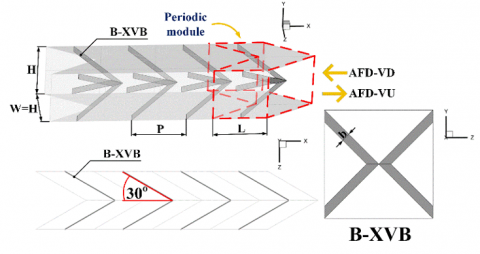
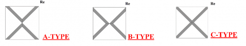
As demonstrated in Figure 1, the system of interest in the current study is a heat exchanger square duct (HX-SD) fitted with X-V baffle (XVB) turbulence generators. The height of the HX-SD, represented by H, is 0.05 m. Since the HX-SD has a square cross section, the width, represented by W, is equal to H. The name "XVB" comes from the shape of the baffles: when viewed in the y-z plane (the CS plane), they appear as an "X" shape, while in the x-z plane, they form a "V" shape. The XVB can be classified into three different types: Type A, Type B, and Type C, with the differences among them clearly visible in the CS plane. XVB Types A, B, and C are illustrated in Figures 1(a-c), respectively. The thickness of the XVB plates for all three types is denoted as b. The ratio of XVB thickness to duct height, b/H, is referred to as the B-R ratio. The B-R values for this study are set to 0.05, 0.10, 0.15, and 0.20. The selection of this ratio range is referenced from [24, 25], which suggests that the appropriate range falls between 0.05 and 0.20. The spacing between the XVB plates, denoted by P, is expressed as the ratio of spacing to tube height, P/H, which is fixed at 1 for all case studies. The angle of attack in all case studies is set to 30o. This choice is based on the findings of [24-26], which show that a pitch ratio of 1 and a flow attack angle of 30o provide the optimal ratio of heat transfer enhancement to friction factor increase. The length of the periodic module, represented by L, is 0.05 m. The flow direction of the air is studied in both the +x and -x directions. The +x flow direction is referred to as the air flow direction-V-Downstream (AFD-VD), while the -x flow direction is referred to as air flow direction-V-Upstream (AFD-VU).
(a)
(b)
(c)
Figure 1. Numerical models of the HX-SD inserted with XVB for (a) A-XVB, (b) B-XVB and (c) C-XVB
In this research, a periodic module-based numerical modeling approach is used to reduce the number of meshes and simulation time. The computational boundary conditions for the HX-SD model with XVB installation are specified as periodic at both the entry and exit, indicating that the flow structure and heat transfer exhibit periodic or self-similar behavior. The periodic model is typically applied to HX-SD systems in industrial plants with long lengths, where inlet effects are negligible. The HX-SD walls on all four sides are subjected to heat flux boundary conditions with a constant value of 600 W/m², and the HX-SD surface follows a no-slip condition. The XVB plates are modeled as thermal insulators, meaning the heat flux is set to 0 W/m². The developed model utilizes a hexahedral grid with non-uniform refinement, ensuring higher resolution near the HX-SD surface. This refinement is necessary due to the significant variations in the boundary layer in this region.
From the reference [25], the boundary of the present research, including the hypotheses for this investigation, is reported as follows:
From the assumptions and initial conditions of the current investigation stated above, the equations related to this work are as follows:
Continuity equation:
$\frac{\partial}{\partial x_i}\left(\rho u_i\right)=0$ (1)
Momentum equation:
$\frac{\partial}{\partial x_i}\left(\rho u_i u_j\right)=-\frac{\partial p}{\partial x_i}+\frac{\partial}{\partial x_j}\left[\mu\left(\frac{\partial u_i}{\partial x_j}\right)-\rho \overline{u_i^{\prime} u_j^{\prime}}\right]$ (2)
where, $\rho, u_{i}, p, \mu$ and $u^{\prime}$ represent air density, mean component of velocity (in the direction $x_i$), pressure, dynamic viscosity and fluctuating component of velocity, respectively.
Energy equation:
$\frac{\partial}{\partial x_i}\left(\rho u_i T\right)=\frac{\partial}{\partial x_j}\left[\left(\Gamma+\Gamma_t\right) \frac{\partial T}{\partial x_j}\right]$ (3)
where, $\Gamma$ represents molecular thermal diffusivity, while $\Gamma_{\mathrm{t}}$ is turbulent thermal diffusivity, and are calculated by:
$\Gamma=\mu / P r$ and $\Gamma_t=\mu_t / P r_{\mathrm{t}}$ (4)
The Reynolds-averaged approach to turbulent modeling involves that the Reynolds stresses, $-\rho \overline{u_i^{\prime} u_j^{\prime}}$ in Eq. (2), be modeled. Eq. (5) displays the Boussinesq hypothesis relates the Reynolds stresses to the mean velocity gradients:
$-\rho \overline{u_i^{\prime} u_j^{\prime}}=\mu_t\left(\frac{\partial u_i}{\partial x_j}+\frac{\partial u_j}{\partial x_i}\right)-\frac{2}{3}\left(\rho k+\mu_t \frac{\partial u_i}{\partial x_i}\right) \delta_{i j}$ (5)
where, the turbulent kinetic energy, $k$, is defined by $k=$ $\left(\overline{u_i^{\prime} u_i^{\prime}}\right) / 2$ and $\delta_{i j}$ is a Kronecker delta. A benefit of the Boussinesq approach is the relatively low computational cost related with the computation of the turbulent viscosity, $\mu_t$ given is $\mu_t=\rho C_\mu k^2 / \varepsilon$. The RNG $k-\varepsilon$ model is an example of the two-equation models that use the Boussinesq hypothesis. The RNG $k-\varepsilon$ model is derived from the instantaneous NavierStokes equation with the "renormalization group" (RNG) method. The steady state transport equations are stated as:
$\frac{\partial}{\partial x_i}\left(\rho k u_i\right)=\frac{\partial}{\partial x_j}\left(\alpha_k \mu_{e f f} \frac{\partial k}{\partial x_j}\right)+G_k-\rho \varepsilon$(6)
$\frac{\partial}{\partial x_i}\left(\rho \varepsilon u_i\right)=\frac{\partial}{\partial x_j}\left(\alpha_k \mu_{e f f} \frac{\partial \varepsilon}{\partial x_j}\right)+C_{1 \varepsilon} \frac{\varepsilon}{k} G_k-C_{2 \varepsilon} \rho \frac{\varepsilon^2}{k}-\mathrm{R}_{\varepsilon}$ (7)
The $\alpha_k$ means the inverse effective Prandtl number for $k$, while $\alpha_{\varepsilon}$ stands for $\varepsilon . C_{1 \varepsilon}$ and $C_{2 \varepsilon}$ remain constants. The effective viscosity $\mu_{\text {efff }}$ is printed as follows:
$\mu_{e f f}=\mu+\mu_t=\mu+\rho C_\mu \frac{k^2}{\varepsilon}$ (8)
where, $C_u$ is constant and identical to 0.0845.
The governing equations were discretized using the QUICK numerical-scheme, decoupled with the SIMPLE algorithm, and solved with a finite volume approach (commercial code/program). When the normalized residual values for all variables were less than 10−5 and for the energy equation less than 10−9, the solutions were taken to be convergent. The Reynolds number, friction factor, local Nusselt number, average Nusselt number, and thermal performance enhancement factor are given by Eqs. (9) through (13), respectively:
$R e=\frac{\rho \bar{u} D_h}{\mu}$ (9)
$f=\frac{(\Delta p / L) D_h}{1 / 2 \rho \bar{u}^2}$ (10)
$N u_x=\frac{h_x D_h}{k}$ (11)
$N u=\frac{1}{A} \int N u_x d A$ (12)
$\begin{aligned} & T E F=\left.\frac{h}{h_0}\right|_{p p}=\left.\frac{N u}{N u_0}\right|_{p p}=\frac{\left(N u / N u_0\right)}{\left(f / f_0\right)^{1 / 3}} =(N u-\text { ratio }) /(f-\text { ratio })^{1 / 3}\end{aligned}$ (13)
where, $N u_0$ and $f_0$ stand for the Nusselt number and friction factor for the smooth HX-SD, respectively.
The process of validating the developed model is a crucial and essential step in numerical modeling studies. In this research, the numerical validation of the created domain is divided into three parts: Validation of the plain HX-SD: This involves comparing the Nusselt number (Nu) and friction factor (f) values obtained from the developed model with those from correlation equations. Selection of an appropriate grid resolution: This step compares the Nu-ratio and f-ratio obtained from the developed model at varying grid resolutions. Comparison with experimental results: This entails comparing the Nusselt number and friction factor derived from the developed model with results obtained from actual experimental studies.
4.1 Validation of the plain HX-SD
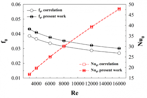
Figure 2 shows the relationship between the f₀ and Nu₀ values with Re, comparing the results from the developed domain with those from the correlation equations [26]. From the figure, it can be found that the f₀ value tends to decline as Re rises, while the Nu₀ value tends to enhance with increasing Re. The trends observed in the study are consistent for both the numerical model and the experimental results. The f₀ value obtained from the correlation equations is lower than that from the current model, with an average difference of 12%. Although the difference in friction factor values is relatively high, the overall trend remains consistent. The two curves do not intersect at any Reynolds number, and the discrepancy does not exceed 15%. Therefore, the results are still within an acceptable range [26]. On the other hand, the Nu₀ values from both sources show very little difference, with an average difference of only 0.7%.
Figure 2. Smooth HX-SD validation
4.2 Selection of an appropriate grid resolution (grid independence)
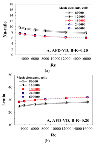
Figures 3(a-b) report the relationship between the Nu-ratio (or Nu/Nu0) and f-ratio (or f/f0) values with Re, respectively, for the numerical model of a HX-SD with XVB type A installed, exhibiting an AFD-VD flow direction and a B-R value of 0.20. From the figures, it can be observed that the trends of the Nu-ratio and f-ratio for all models follow the same pattern: the Nu-ratio decreases slightly, while the f-ratio increases slightly as Re increases. Numerical domains with a grid count varying from 80,000 to 120,000 exhibit a noticeable difference in Nu-ratio and f-ratio values compared to those with a grid count of 180,000 or higher. Therefore, considering the research duration and available computational resources, this study opted to develop models with a grid count of 180,000 for all cases examined.
Figure 3. Grid independence for (a) Nu-ratio and (b) f-ratio
4.3 Comparison with experimental results
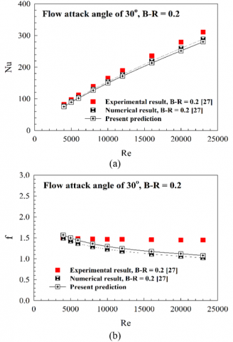
An essential step in numerical modeling analysis is the comparison of results with previously published research [27]. For this purpose, models with characteristics similar to the current study were selected to ensure relevance and accuracy. The comparison is illustrated in Figures 4(a-b), which present the Nusselt number and friction factor, respectively. The numerical results indicate that the trends of both the Nusselt number and the friction factor are consistent. In particular, as the Reynolds number rises, the friction factor tends to decrease and the Nusselt number tends to rise. All three components' values fall within a reasonable range of fluctuation.
Figure 4. Comparison between present prediction and the previous work [27]
The created model is sufficiently accurate for predicting air flow profile and thermal parameters within HX-SD installed with vortex generators, according to the validation analysis of the three model parts.
The results of this study are separated into two major parts. Part 1 explains the behavior within the HX-SD, including both fluid-flow pattern and thermal structure. Part 2 analyzes the thermal performance of the HX-SD. Part 1 is presented through flow streamlines, fluid temperature contours/distributions, and Nusselt number contours/distributions. Part 2 is reported using dimensionless variables, including pressure drop, heat transfer, and thermal performance. The pressure drop is represented by the ratio of the friction factor of the HX-SD with XVB installation to that of a smooth, empty HX-SD, denoted as the f-ratio. Heat transfer is expressed as the ratio of the Nusselt number of the HX-SD with XVB to that of the smooth, empty HX-SD, referred to as the Nu-ratio. The thermal enhancement factor (TEF) is defined as the ratio of the Nu-ratio to the f-ratio raised to the same power.
5.1 Flow description
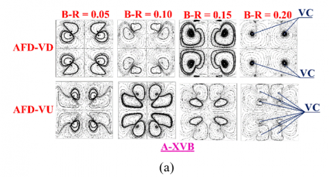
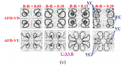
In order to analyze the thermo-hydraulic efficiency within the HX-SD with XVB installation, it is necessary to first understand the air-flow topology and thermal configuration occurring through the HX-SD. The working-fluid streamlines (air) in the CS plane of the HX-SD with XVB installation for types A, B, and C, respectively, at Reynolds number of 4000, for various B-R values and flow directions, are displayed in Figures 5(a)-(c). As seen in the figures, the installation of XVB in the HX-SD significantly affects the air flow. The XVB installation obstructs the flow, leading to a pressure drop. This pressure drop induces the formation of VTF as the air passes through the XVB. The VTF characteristics, when observed in the CS plane for all B-R values and flow directions, can be divided into four distinct regions due to the shape of the XVB. The flow structure exhibits symmetry both in the upper and lower sections, as well as in the left and right sides. The vortex core, denoted as VC, varies in number and position depending on the B-R value and air flow direction. The number of VCs can be observed to range from 4 to 8 axes. When examining the VTF in the lower half of the CS plane, at the centerline dividing the VTF, it is observed that different flow directions affect the vortex rotation (in the CS plane) in opposite directions. For example, at B-R=0.05 for XVB Type A, the AFD-VU flow direction results in a common-flow-up behavior (observed at the centerline of the lower pair of vortices), whereas the AFD-VD flow direction results in a common-flow-down behavior. These differences in flow characteristics affect the VTF strength, which is associated to the heat transfer behavior occurring in the HX-SD. In other words, when the fluid-flow behavior differs, the heat transfer characteristics also vary accordingly. The flow streamlines in the CS plane for all three XVB types are similar but not identical, due to the differences in the structure of each XVB type.
Figure 5. Streamlines in CS planes for the HX-SD inserted with XVB for (a) A-XVB, (b) B-XVB and (c) C-XVB at various B-R values at Re = 6000
After explaining the flow structure that occurs when XVB is installed in the HX-SD, this section will focus on the benefits or advantages gained from the VTF that is induced by the XVB installation. The VTF occurring within the HX-SD can affect the heat transfer rate or the heat transfer capability. Part of the VTF, which is strong enough and occurs near the HX-SD surface or HX-SD wall, results in impingement on the surface of the HX-SD. The thermal boundary layer (Th-BL), or more specifically, the boundary layer close to the surface, is disturbed by this impingement. The Th-BL of the internal HX-SD surfaces becomes thinner as a result of the disturbance. An increase in the heat transfer rate (Nusselt number) is directly correlated with a decrease in the thickness of the boundary layer, which raises the local convective heat transfer coefficient. The quality of the air mixing between the hot air close to the HX-SD surface and the cooler air in the center of the HX-SD is improved by another feature of the VTF. The improved mixing quality of the air is another factor that positively impacts heat transfer, as it promotes more uniform temperature distribution and improves HX-SD efficiency.
The impingement of the flow in the HX-SD with XVB installation can be seen in Figures 6(a)-(b), which present the 3D flow streamlines in a HX-SD with XVB Type A for the AFD-VD and AFD-VU flow directions, respectively. The researcher plotted this image by using a tool that specifically captures the flow impingement at the wall, where yellow arrows are displayed. This indicates that part of the VTF actually impinges on the HX-SD wall. The impingement behavior occurs in a similar manner for Types A, B, and C; therefore, Type A is selected to represent the flow characteristics in the presentation.
Figure 6. Impinging flow on the HX-SD wall for (a) AFD-VD and (b) AFD-VU
The presentation of flow streamlines in the CS plane and 3D flow streamlines cannot be used as tools to explain the changes or to observe the Th-BL, as well as the flow strength. Therefore, in the next section, temperature contours in the CS plane are presented. This is an essential tool that effectively helps explain the changes in the Th-BL and can also describe the flow strength.
5.2 Thermal structure
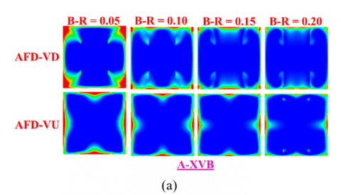
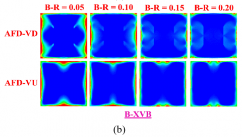
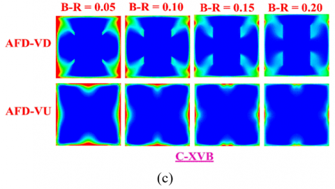
The temperature contours of the air in the HX-SD's CS plane with XVB Types A, B, and C, respectively, at Re = 4000 are displayed in Figures 7(a)-(c). As mentioned in the previous section, temperature contours in the CS plane are useful for explaining changes in the Th-BL. From the figures, it is evident that near the HX-SD surface, the air exhibits red contours, indicating high temperatures, while the air in the middle of the tube, or farther from the surface, shows blue or green contours, indicating lower temperatures. The XVB installation induces VTF, which disturbs the Th-BL, causing it to thin. This thinning can be observed in the red temperature contours, which become slenderer. Thinner contours indicate a disturbance in the Th-BL. For all three XVB types, increasing the B-R value leads to a further thinning of the Th-BL. This is because an increased pressure drop is caused by a rise in the flow obstruction ratio, or B-R. The higher-pressure drop induces stronger VTF, which disrupts the Th-BL more effectively. At B−R = 0.20, the flow intensity and impingement are strongest, while at B−R = 0.05, the flow intensity and impingement are weakest. However, the figures in this section do not adequately compare the flow strength between the different XVB types and flow directions. A comparison of flow strength should be presented using dimensionless variables.
Figure 7. Temperature contours in CS planes for the HX-SD inserted with XVB for (a) A-XVB, (b) B-XVB and (c) C-XVB at various B-R values at Re = 6000
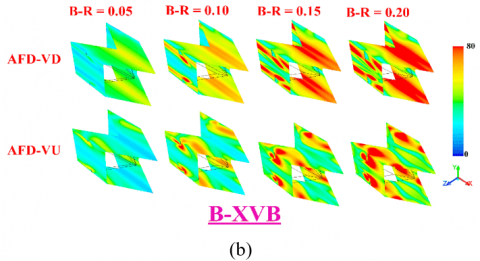
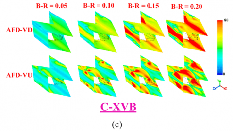
Figure 8. Local Nusselt number contours in CS planes for the HX-SD inserted with XVB for (a) A-XVB, (b) B-XVB and (c) C-XVB at various B-R values at Re = 6000
As previously discussed, the VTF induced by XVB installation causes part of the flow to impinge upon the internal HX-SD surface, disturbing the Th-BL and reducing its thickness. This reduction leads to an increase in the local convective heat transfer coefficient (local Nusselt number). Plots of the local Nusselt number distributions (Nux) on the HX-SD surface are shown to demonstrate this. Figures 8(a)-(c) display these plots for XVB Types A, B, and C, respectively, at Re = 4000. The red contours represent regions with higher Nusselt numbers, indicating increased heat transfer rates, while the blue contours correspond to areas with lower Nu, typically associated with lower heat transfer rates. The red contours are found in regions where the flow impinges on the surface, significantly enhancing Nu. The blue contours, referred to as the "dead zone," are typically located behind the XVB and along the HX-SD edges, where the heat transfer rate is lower.
It is evident that the heat transfer behavior varies significantly between different study cases. As an illustration, good heat transfer is seen on the HX-SD's left and right walls when XVB Type A is flowing in the AFD-VD direction. In contrast, for the AFD-VU flow direction, the red contours are less spread and more evenly distributed across all four walls. Increasing the B-R value enhances flow strength, which raises the disturbance level in the near-wall Th-BL, resulting in a noticeable increase in heat transfer. At B−R=0.20, the highest rate of heat transfer is observed, while at B−R=0.05, the lowest rate is achieved. The AFD-VD flow direction provides better heat transfer than AFD-VU.
This section presents the fluid flow behavior and heat transfer structure occurring in HX-SD equipped with XVB, which enables a better understanding of the phenomena. The study's findings are shown in the next section as dimensionless variables, which makes it possible to compare heat transfer rates, pressure decreases, and thermal performance in numerical terms across multiple case studies.
5.3 Performance assessment
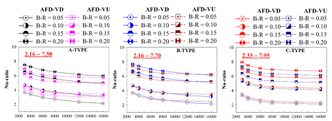
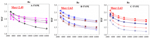
The relationship between the Reynolds number and the Nu-ratio (Nu/Nu0), f-ratio (f/f0), and TEF for HX-SD with XVB across multiple case studies is shown in Figure 9. The figure shows that the Nu-ratio and TEF decrease as the Reynolds number increases, while the f-ratio exhibits an increasing trend with higher Reynolds numbers. These trends are consistent across all XVB types.
Figure 9. Performance analysis for the HX-SD inserted with XVB
When XVB is installed in HX-SD, the heat transfer rate is greatly increased in comparison to plain smooth HX-SD; in every case, the Nu-ratio is greater than 1. Within the study range, the Nu-ratio values are 2.16–7.50, 2.16–7.70, and 2.33–7.95 for XVB types A, B, and C, respectively. At B−R = 0.20, the highest heat transfer rate is achieved, whereas B−R = 0.05 yields the lowest. For B−R = 0.20, the AFD-VD flow pattern outperforms AFD-VU in terms of heat transfer rate. However, at B−R = 0.05 and B−R = 0.10, the heat transfer rates for AFD-VD and AFD-VU are nearly identical. Among the three types, XVB type C delivers the highest heat transfer performance, followed by type B, which slightly outperforms type A.
In addition to increasing the rate of heat transfer, installing XVB in HX-SD also raises the friction factor ratio, especially at higher B-R values. This increase in friction factor raises concerns for overall thermal performance, as a higher friction factor requires more pump power to maintain flow. In all case studies, the f-ratio for HX-SD with XVB installation is greater than 1, indicating that it exceeds the friction factor of plain smooth HX-SD. The f-ratio values range from 4.06–32.18, 4.21–33.68, and 4.09–45.82 for XVB types A, B, and C, respectively. For XVB type C, the f-ratio is nearly identical for both flow directions. For type B, the f-ratio values are almost the same, except at B−R = 0.20, where the AFD-VU flow direction results in a higher value than AFD-VD. For XVB type A, the f-ratio values are similar at B−R = 0.05 and B−R = 0.10, but at B−R = 0.15 and B−R = 0.20, the AFD-VD flow direction results in a higher value than AFD-VU.
When XVB is installed in HX-SD, the rate of heat transfer increases along with the pressure drop. The thermal system benefits from the improved heat transfer, but the system suffers since the higher-pressure drop necessitates greater pump power. Heat transfer and pressure drop must therefore be taken into account in a thorough evaluation of the advantages of XVB installation. This analysis uses the TEF, which assesses the improvement in heat transfer rate at the same pumping power. In this study, the TEF is greater than 1 in all cases, indicating that XVB installation provides better performance than plain smooth HX-SD. For XVB types A, B, and C, the greatest TEF values recorded are 2.49, 2.63, and 2.63, respectively; the highest values are recorded at Re = 3000. B-R = 0.15 for type A, B-R = 0.20 for type B, and B-R = 0.15 for type C are the greatest TEF values. The best results are obtained when the flow direction is AFD-VD.
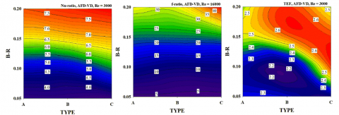
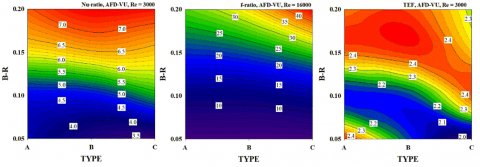
Figure 10 illustrates the contours of the Nu-ratio, f-ratio, and TEF. The Nu-ratio and TEF are shown at Re = 3000, while the f-ratio is displayed at Re = 16000. It is clear from the graphic that the f-ratio and Nu-ratio both rise in proportion to height. The results are consistent for both AFD-VD and AFD-VU. The TEF reaches its maximum value at B-R between 0.15 and 0.20, depending on the type of XVB.
Figure 10. Nu-ratio (at Re = 3000), f-ratio (at Re = 16000) and TEF (at Re = 3000) contours
This study examines the use of passive techniques to rise heat transfer ability in HX-SD. The installation of XVB-type vortex generators is chosen as the passive method to enhance heat transfer rates. This approach is popular in the industry because it minimally impacts energy consumption and operational costs. The research investigates the impact of XVB thickness, XVB type, and fluid-flow direction on airflow pattern, as well as the resulting changes in heat transfer characteristics. The focus is on turbulent airflow, with Reynolds numbers ranging from 3,000 to 16,000 (calculated based on inlet conditions). This flow regime is relevant to a wide range of engineering applications. A numerical simulation approach was selected for the study, as it effectively explains the behavior occurring within HX-SD. The findings from this research can be concluded and stated as follows:
Flow Behavior: The pressure difference or pressure drop between the front and rear of the XVB is immediately impacted when XVB vortex generators are fitted in HX-SD because they block the flow. VTF is created when airflow through the XVB is induced by this pressure difference. The induced VTF benefits the heat transfer system. Part of the VTF, with sufficient intensity and proximity to the heat transfer surface, collides with the HX-SD walls. This interaction alters the Th-BL, causing it to thin. Another portion of the VTF, which does not collide with the HX-SD walls, contributes to improved fluid mixing. It improves the interaction between the warmer fluid close to the HX-SD walls and the colder fluid in the middle of the HX-SD. Two important elements that improve the heat transfer rate and overall thermal performance are the disruption of the Th-BL and the enhanced fluid mixing.
Thermal Behavior: As mentioned in the flow behavior section, the VTF generated by the XVB disturbs the Th-BL, causing it to thin. The local convective heat transfer coefficient rises as a result of this occurrence, and it is directly correlated with the Nusselt number and the heat transfer rate. The thinning of the Th-BL does not occur uniformly across the entire surface, but only in areas where the flow impinges. Therefore, the regions where the flow impacts provide better heat transfer rates compared to other areas.
Influence of XVB Thickness: The thickness of the XVB affects the intensity of the VTF. As the thickness of the XVB increases, the pressure drops across it also increases, leading to stronger VTF. The intensity of the VTF impacts the heat transfer rate, as a stronger VTF results in higher impingement forces on the HX-SD surface, which are directly proportional to the heat transfer rate. In the study, it was observed that at a B-R value of 0.20, the f-ratio and Nu ratio were maximized. On the other hand, at a B-R value of 0.05, the results showed the opposite trend.
Influence of Flow Direction: Different flow directions affect the flow behavior, including the regions where VTF impinges. When VTF impinges at different locations, it results in noticeable variations in the points where the maximum values of the local convective heat transfer coefficient occur.
Influence of XVB Type: In this study, three types of XVB were created: A, B, and C. All three types differ at the midpoint when considering the CS flow plane (x-z plane). Although the differences between the XVB types were not significant, they noticeably affected both the heat transfer rate and the pressure drop. The highest pressure drop and heat transfer were observed with XVB type C, with values 45.82 times and 7.95 times greater than those of a smooth, empty HX-SD, respectively.
Additional Recommendations and Future Research: For the development of XVB for use in real-world industrial heat exchangers, the researchers found that the ease of manufacturing the three types of XVB did not differ significantly. Among them, XVB type C was the most stable when installed in actual heat exchangers. Regarding the TEF (Thermal Enhancement Factor) of the three XVB types, types B and C provided the highest values, at 2.63, while type A reached a maximum value of 2.49.
This study achieves the highest TEF value of 2.63, outperforming previously published research. For comparison, studies incorporating delta winglets with nanofluids [28] reported a maximum TEF of 2.2, the use of twisted tape [29] resulted in a TEF of 1.8, wavy ribs [30] achieved a TEF of 1.55, and delta winglets alone [31, 32] provided only 1.1. It is evident that the developed approach in this study offers a significantly higher TEF. Additionally, it ensures a high level of stability for implementation in practical heat exchanger systems.
For future investigation, the researchers plan to further develop XVB to augment the heat transfer potentiality while aiming to maintain or even reduce the pressure drop within the heat exchanger system. We will explore increasing the thickness of the XVB while incorporating holes to reduce the pressure drop. However, drilling holes may affect the heat transfer rate, as the flow velocity through smaller openings will increase, potentially leading to stronger impingement over the heat exchanger surface, which could further enhance heat transfer.
The authors would like to thank Prof. Dr. Pongjet Promvonge for suggestions.
|
b |
XVB height, m |
|
Cμ |
constant value (=0.0845) |
|
Dh |
hydraulic diameter (=H for HX-SD), m |
|
f |
friction factor, friction loss |
|
f-ratio |
f/f0 |
|
h |
convective heat transfer coefficient, W m-2 K-1 |
|
H |
HX-SD height (=HX-SD width), m |
|
k |
turbulent kinetic energy, $k=\left(\overline{u_i^{\prime} u_i^{\prime}}\right) / 2$ |
|
kt |
thermal conductivity, W m-1 K-1 |
|
L |
numerical model length/periodic length |
|
Nu |
Nusselt number |
|
Nu-ratio |
Nu/Nu0 |
|
p |
static pressure, Pa |
|
P |
pitch spacing, m |
|
Pr |
Prandtl number |
|
Re |
Reynolds number |
|
T |
fluid temperature, K |
|
$\bar{u}$ |
fluid mean velocity in square duct, m s-1 |
|
ui |
mean component of velocity in the direction xi, m s-1 |
|
u' |
fluctuating component of velocity, m s-1 |
|
Greek symbols |
|
|
ρ |
density, kg m-3 |
|
µ |
dynamic viscosity, kg m-1s-1 |
|
μeff |
effective viscosity |
|
μt |
turbulent viscosity, $\mu_t=\rho C_\mu k^2 / \varepsilon$ |
|
$\alpha_{k}$ |
inverse effective Prandtl number for k |
|
$\alpha_{\varepsilon}$ |
inverse effective Prandtl number for ε |
|
$\Gamma$ |
molecular thermal diffusivity |
|
$\Gamma_t$ |
turbulent thermal diffusivity |
|
$\delta_{i j}$ |
a Kronecker delta |
|
Subscripts |
|
|
0 |
smooth HX-SD |
|
pp |
driving force |
|
Abbreviations |
|
|
AFD-VD |
air flow direction-V-Downstream |
|
AFD-VU |
air flow direction-V-Upstream |
|
B-R |
blockage ratio (b/H) |
|
CS |
cross-sectional |
|
HX-SD |
heat exchanger square duct |
|
TEF |
thermal enhancement factor (=(Nu/Nu0)/(f/f0)1/3) |
|
Th-BL |
thermal boundary layer |
|
VC |
vortex core |
|
VTF |
vortex flow |
|
XVB |
X-V baffle |
[1] Mukhlif, E.A., Abed, W.M. (2024). Influences of submerged V-broken rib geometry on the hydrothermal performance of vortex and engulfment flow regimes within a T-channel. International Communications in Heat and Mass Transfer, 159: 108325. https://doi.org/10.1016/j.icheatmasstransfer.2024.108325
[2] Kumar, A., Pathak, M. (2024). Flow and heat transfer characteristics of gas turbine blade channels with compound V-rib-dimple structures. International Communications in Heat and Mass Transfer, 157: 107823. https://doi.org/10.1016/j.icheatmasstransfer.2024.108325
[3] Sutar, S., Rout, S.K., Senapati, J.R., Barik, D., Dennison, M.S., Praveenkumar, S. (2024). Numerical investigation on the thermohydraulic performance of a solar air heater duct featuring parabolic rib turbulators on the absorber plate. Case Studies in Thermal Engineering, 64: 105399. https://doi.org/10.1016/j.csite.2024.105399
[4] Hegde, A.K., Pai, R., Karanth, K.V. (2024). Influence of solar insolation on energy and exergy efficiency of a rectangular duct solar air heater with various types of V rib roughness: An analytical approach. International Communications in Heat and Mass Transfer, 153: 107397. https://doi.org/10.1016/j.icheatmasstransfer.2024.107397
[5] Liu, C., Bao, Y., Li, B., Lyu, P., Liu, X., Rao, Z. (2025). Experimental study on heat transfer enhancement and flow performance of microencapsulated phase change slurry in microchannel with different rib structures. International Journal of Heat and Mass Transfer, 237: 126437. https://doi.org/10.1016/j.ijheatmasstransfer.2024.126437
[6] Wang, L., Lv, C., Liu, X., Mao, J., Zhang, D., Liu, Y., Li, M. (2024). Research on improving heat transfer performance by using wavy ribs with different cross sections. Applied Thermal Engineering, 257: 124397. https://doi.org/10.1016/j.applthermaleng.2024.124397
[7] Majmader, F.B., Hasan, M.J. (2024). Effects of bidirectional rib arrangements on turbulent flow structure and heat transfer characteristics of a two-pass channel for turbine blade internal cooling. International Communications in Heat and Mass Transfer, 156: 107688. https://doi.org/10.1016/j.icheatmasstransfer.2024.107688
[8] Chhaparwal, G.K., Goyal, R., Srivastava, A., Goyal, A., Oza, A.D., Siddiqui, M.I.H., Natrayan, L., Kumar, L., Chandrakant, S. (2024). Numerical and experimental investigation of a solar air heater duct with circular detached ribs to improve its efficiency. Case Studies in Thermal Engineering, 60: 104780. https://doi.org/10.1016/j.csite.2024.104780
[9] Wang, Q., Tao, J., Cui, Z., Zhang, T., Chen, G. (2024). Numerical simulation of fluid and heat transfer characteristics of microchannel heat sink with fan-shaped grooves and triangular truncated ribs. International Communications in Heat and Mass Transfer, 155: 107580. https://doi.org/10.1016/j.icheatmasstransfer.2024.107580
[10] Fu, H., Sun, H., Luan, J., Yang, L., Luan, Y., Magagnato, F. (2024). The heat transfer enhancement mechanism of W-shaped micro-ribs on impingement cooling. Applied Thermal Engineering, 252: 123658. https://doi.org/10.1016/j.applthermaleng.2024.123658
[11] Wang, L., Lv, C., Mao, J., Li, Y., Zhang, D., Liu, X. (2024). Effects of non-uniform wavy ribs on flow and heat transfer characteristics of turbine blade cooling channel. Applied Thermal Engineering, 248: 123249. https://doi.org/10.1016/j.applthermaleng.2024.123249
[12] Prasad, J.S., Datta, A., Mondal, S. (2024). Numerical analysis of a solar air heater with offset transverse ribs placed near the absorber plate. Renewable Energy, 227: 120608. https://doi.org/10.1016/j.renene.2024.120608
[13] Jia, Y.T., Zhang, D.X., Wang, J.T., Xia, G.D. (2024). Experimental study on flow boiling characteristics in microchannels with trapezoidal rib walls. International Communications in Heat and Mass Transfer, 155: 107545. https://doi.org/10.1016/j.icheatmasstransfer.2024.107545
[14] Boonloi, A., Jedsadaratanachai, W. (2023). Thermal behaviors and flow profiles in a square channel fitted with X–V modified ribs: A numerical analysis. Case Studies in Thermal Engineering, 49: 103282. https://doi.org/10.1016/j.csite.2023.103282
[15] Hu, J., Chen, C., Wang, X., Xin, G., Wang, M. (2024). Improvement of flow and heat transfer performance of microchannels with different ribs using topology optimization. Applied Thermal Engineering, 244: 122672. https://doi.org/10.1016/j.applthermaleng.2024.122672
[16] Tamang, S., Ali, E., Park, H. (2024). A novel concept for a rib turbulator for optimizing the cooling performance in a square channel. International Journal of Heat and Mass Transfer, 221: 125144. https://doi.org/10.1016/j.ijheatmasstransfer.2023.125144
[17] Xu, M., Liu, J., Xi, W., Liu, C., Sunden, B. (2024). Thermodynamic performance and flow structures analysis of supercritical CO2 applied in a regenerative cooling channel mounted with mini-ribs. Case Studies in Thermal Engineering, 60: 104704. https://doi.org/10.1016/j.csite.2024.104704
[18] Ahmed, E.N., Tanda, G. (2024). An experimental and numerical study of laminar natural convection along vertical rib-roughened surfaces. International Journal of Heat and Mass Transfer, 223: 125227. https://doi.org/10.1016/j.ijheatmasstransfer.2024.125227
[19] Yan, H., Chen, Z., Luo, L., Du, W., Zeng, F., Wang, S., Guo, L. (2024). Heat transfer enhancement of return channel by using rib turbulator for a new impingement cooling scheme. International Communications in Heat and Mass Transfer, 151: 107237. https://doi.org/10.1016/j.icheatmasstransfer.2023.107237
[20] Li, B., Cui, Y., Li, G., Jiang, H. (2024). Numerical analysis on thermal-hydraulic performance of optimized microchannel heat sink with slant ribs and quatrefoil rib-elliptical groove complex structures. Applied Thermal Engineering, 240: 122165. https://doi.org/10.1016/j.applthermaleng.2023.122165
[21] Shanmugam, A.R., Park, K.S. (2024). Flow and heat transfer of supercritical hydrogen in a regenerative cooling channel with the arc ribs of a rocket engine. Applied Thermal Engineering, 236: 121451. https://doi.org/10.1016/j.applthermaleng.2023.121451
[22] Zheng, S.F., Liu, G.Q., Zhang, Y., Wang, H.C., Gao, S.R., Yang, Y.R., Li, H.W., Sunden, B., Wang, X.D. (2023). Performance evaluation with turbulent flow and heat transfer characteristics in rectangular cooling channels with various novel hierarchical rib schemes. International Journal of Heat and Mass Transfer, 214: 124459. https://doi.org/10.1016/j.ijheatmasstransfer.2023.124459
[23] Zhu, Q., Wang, Z., Zeng, J., Wen, X., Deng, H., He, W., Zhao, T. (2024). Numerical study on flow and heat transfer in a novel symmetric sinusoidal wavy microchannel heat sink with rectangular rib prisms. International Journal of Thermal Sciences, 197: 108807. https://doi.org/10.1016/j.ijthermalsci.2023.108807
[24] Boonloi, A., Jedsadaratanachai, W. (2022). 3D-numerical predictions of flow structure and heat transfer behavior in heat exchanger tubes inserted with different patterns of double-V baffles. Case Studies in Thermal Engineering, 39: 102385. https://doi.org/10.1016/j.csite.2022.102385
[25] Boonloi, A., Jedsadaratanachai, W. (2025). Turbulent forced convection in a square duct heat exchanger (SDHX) equipped with combined vortex turbulators (CVT): A numerical investigation. International Communications in Heat and Mass Transfer, 161: 108421. https://doi.org/10.1016/j.icheatmasstransfer.2024.108421
[26] Cengel, Y.A., Ghajar, A.J. (2015). Heat and Mass Transfer: Fundamentals & Applications. Fifth edition in SI Units, McGraw-Hill Education.
[27] Promvonge, P., Skullong, S., Kwankaomeng, S., Thiangpong, C. (2012). Heat transfer in square duct fitted diagonally with angle-finned tape—Part 1: Experimental study. International Communications in Heat and Mass Transfer, 39: 617–624. https://doi.org/10.1016/j.icheatmasstransfer.2012.03.007
[28] Ekrani, S.M., Ganjehzadeh, S., Esfahani, J.A. (2023). Multi-objective optimization of a tubular heat exchanger enhanced with delta winglet vortex generator and nanofluid using a hybrid CFD-SVR method. International Journal of Thermal Sciences, 186: 108141. https://doi.org/10.1016/j.ijthermalsci.2023.108141
[29] Nakhchi, M.E., Esfahani, J.A. (2019). Numerical investigation of rectangular-cut twisted tape insert on performance improvement of heat exchangers. International Journal of Thermal Sciences, 138: 75-83. https://doi.org/10.1016/j.ijthermalsci.2018.12.039
[30] Boonloi, A., Jedsadaratanachai, W. (2015). Turbulent forced convection in a heat exchanger square channel with wavy-ribs vortex generator. Chinese Journal of Chemical Engineering, 23(8): 1256-1265. https://doi.org/10.1016/j.cjche.2015.04.001
[31] Wang, J., Zeng, L., Fu, T., Yu, S., He, Y. (2024). Effects of the position and perforation parameters of the delta winglet vortex generators on flow and heat transfer in minichannels. International Journal of Thermal Sciences, 198: 108878. https://doi.org/10.1016/j.ijthermalsci.2023.108878
[32] Fu, H., Sun, H., Yang, L., Yan, L., Luan, Y., Magagnato, F. (2023). Effects of the configuration of the delta winglet longitudinal vortex generators and channel height on flow and heat transfer in minichannels. Applied Thermal Engineering, 227: 120401. https://doi.org/10.1016/j.applthermaleng.2023.120401