Qahtan Adnan Saber![]() | Riyadh Alsultani*
| Riyadh Alsultani*![]() | Ahmed Ashor Al-Saadi | Ibtisam R. Karim
| Ahmed Ashor Al-Saadi | Ibtisam R. Karim![]() | Saleh I. Khassaf
| Saleh I. Khassaf![]() | Omran I. Mohammed
| Omran I. Mohammed![]() | Sabah Mohammed Abed
| Sabah Mohammed Abed![]() | Raghda Ali Naser
| Raghda Ali Naser![]() | Alaa Hussein
| Alaa Hussein![]() | Fatima Muslim
| Fatima Muslim![]() | Sepanta Naimi
| Sepanta Naimi![]() | Zahra Salahaldain
| Zahra Salahaldain![]()
© 2025 The authors. This article is published by IIETA and is licensed under the CC BY 4.0 license (http://creativecommons.org/licenses/by/4.0/).
OPEN ACCESS
The paper deals with setting a 3D finite element interaction between soil and bridge piers modeled in DIANA software parallel processing. The main focus is laid on the sustainability of the structure, including unification of hydrodynamic pressure presented by currents-waves of water flow and the seismic effect with the nonlinearity of soil and concrete. Water forces are applied as a distributed loading to the pile foundation of the bridge based on two forms of hydrodynamic pressure, Morison and fifth-order Stokes theory. The paper presents an investigation of structural bridge pier stimulation under elastic conditions including influence of current-wave of flow. The velocity of flow, wave characteristics, and seismic intensity are discussed concerning the structural behavior of the piers which include relative moment, displacement, acceleration, shear, and hydrodynamic pressure. This work has demonstrated that pressure changes due to earthquakes in the hydrodynamic regime modify the behavior of the pier by developing added internal forces in the lower pier and high values of displacement and acceleration at the pier upper. The wave effect must be included in the resilient and sustainable design of bridge infrastructure.
bridge pier, structural response, Morison’s formula, hydrodynamic pressure, current-wave-earthquake, infrastructure sustainability
The demand for intra-urban transportation has been increasing, thus more and more long-span river and canal bridges are constructed [1]. These bridges have to be designed for long-term durability amid some fairly adverse environmental conditions. Typically, deep-water pile foundations would be required [2]. It is, however, currently unknown whether they have seismic resistance, especially if the ground motion is coupled with wave action during an earthquake. Though already proven effective against static and certain dynamic loads (e.g., due to wind and the water flow), their seismic capacity is not yet clear [3, 4].
Many investigations have been conducted both domestically and internationally to study the behavior of water structures in response to dynamic ground motions and waves. Yamada's team [5] employed the Kanai spectrum and waves derived from the Bretschneider power spectrum in order to produce ground shaking. Karadeniz [6] employed spectral analysis on three-dimensional structures and considered the occurrence of earthquakes and waves in water with a depth of more than 80 meters as a random process. In order to assess the seismic behavior of flexible structures taking into account fluid motion and structural stiffness, Fukusumi et al. [7] conducted simple numerical experiments. Etemad et al. [8] employed the Nogami model to study the response of pile foundations to seismic waves and the interaction of pile and soil in different directions of wave travel and ground motion [9].
Abbasi and Gharabaghi calculated the seismic response of a 3 dimensional model of an offshore drilling platform that considered the effects of nonlineality and wave direction. He and Li [10] intended to utilize wave theory and Morrison's formula in order to assess the seismic behavior of structures affected by both quakes and waves. Alsultani et al. [11] employed the added mass approach to simulate the entire pile-soil-column water system and investigated the dynamic pressure and water level changes. In this context, Song et al. [12] created a simple computational procedure to estimate the pressure differential between the water and the solid during an earthquake, this is of great importance to the engineering community. This analysis is crucial to ensuring the proper design and safety of bridges during earthquakes. Additionally, this type of modeling has a significant role in implementing early warning systems and dynamic response mitigation strategies that will ensure that structures can cope with the combined effects of hydrodynamic and seismic forces.
The common lack of consideration of hydrodynamics in the studies that are currently underway underscores the necessity of such analysis. As a result, their conclusions cannot be universally applied or to dynamic scenarios that involve the behavior of deep-sea foundations under seismic pressure. Effective predictions in three-dimensional space must accurately represent the response of the column, pile, soil, and water system to an earthquake. This response must be in terms of the relative displacement, acceleration, sheer, sensitive moment, and hydrodynamic pressure coefficient.
Recent investigations have identified various components of this molecule. In order to assess a cable-stayed bridge that is supported by the seabed from the perspective of earthquake-induced structural interaction, Li et al. [4] conducted underwater shake tables that flickered. This investigation aims to explore the difficulties associated with the interaction of multiple hazardous scenarios and their effect on the stability of the bridge. Other scientists [13] dedicated their research to the way waves and associated currents affect bridge piers and provided significant information regarding the hydrodynamic forces that occur and their association with structural design.
These researchers examined the effectiveness of bridge piers in adverse situations, one example of which was a dynamic rise in flood water caused by a dam failure [1]. Their results indicate that it's vital to consider the responses to piercing from different directions in order to create truly resilient structures that can handle these disasters. Another research by Huynh et al. They advocated the need to consider the long-term effects of environmental factors when predicting quakes. Huynh et al. [14] investigated the temporal evolution of the resistance of offshore structures to seismic action as a function of erosion and corrosion induced by chloride...
The study [15] has been made on hydrodynamic loading, specifically in the wave and flow coupling case of bridge decks. Her work increased our knowledge of complex fluid dynamics and forces resultant in bridge structures. Additionally, in the study by Lu et al. [16], more scopes on hydrodynamics have been done and introduced new designing concepts through the review of research progress and future prospects of column-type floating underwater tunnels.
Several studies have been carried out on the problems associated with high pile cap foundations of offshore bridges. This study brings out the hydrodynamic challenges and proposals for enhancement to the design of these most critical structural elements Dynamic response of bridges to extreme floods was investigated by Zhu et al. [17], which underlines the significance that fluid-soil-structure interaction has on the predictability of design performance in severe events.
Xu and Cai [18] studied the interactions between bridge decks and waves via numerical experiments and determined the importance of lateral stiffness in regards to the dynamic behavior of structures. This research demonstrated the capacity of the bridge's deck structure to resist wave impacts when dealing with a single wave. Other investigations have demonstrated that Qu et al. [19] studied the safety of coastal bridges in the New York metropolitan area during severe storms using the example of Hurricane Sandy as a guide. Their findings indicate the necessity of strong design and alteration strategies in order to preserve coastal infrastructure from future disasters.
The main objective of this study is to further knowledge of the behavior of deepwater pile foundations under extreme loading conditions, through detailed seismic ground motion and wave simulations. Therefore, we will provide engineers and researchers with the necessary information for enhancing the seismic performance of deepwater bridge piers dynamic response hydrodynamic pressure coefficients, relative displacement, acceleration, shear forces, as well as moments. The 3D finite element model to be developed herein will be applied in this work to be able to:
• Enhancing Simulation Accuracy: By accurately representing pile-soil interactions and fluid dynamics, our model improves the fidelity of seismic response predictions for deepwater pile foundations.
• Improving Design Practices: The findings of our research will lead to increased efficiency in the construction of bridges and make sure that the piers of these structures can withstand the effects of a combined earthquake and wave action.
• Long-term Structural Safety: In earthquake-prone areas, addressing the bridge piers' resistance to severe loading conditions helps ensure the durability and security of vital infrastructure. By using sophisticated computational techniques to model intricate interactions between structural elements and environmental forces, this study fills important knowledge gaps. Our goal is to provide engineers and decision-makers with the necessary resources to create and manage robust bridge infrastructure in demanding maritime settings.
Please acknowledge that this instance [20] takes the multi-span bridge, the structure spanning the Songhua River. One very compelling argument that had this bridge as the case study was the incredibly complicated structure created and also the extremes of hydrodynamic plus seismic issues of that particular location.
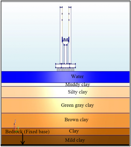
The high columns are rectangular in shape, 4.8 meters long and 2.4 meters wide. Nine rectangular-shaped cross sections support the top of the piers, 3 meters high and 12 meters wide. The circular stacks have a height of 58 m, a diameter of 1.8 m and a cross section of 12 m away from the current scour line. The distance between the columns is 4.5 meters. A 12 meter-wide deck is present that is designed to have a 4-lane dual carriageway with a mass of 7.8×10^5 kg, this contributes to the greatest possible load on the columns. The bridge's deck and piers are composed of C35 concrete that has a modulus of 31.5 GPA, the abutments and supports are composed of C30 concrete that has a modulus of 28 GPA [21, 22].
Figure 1 gives a fair idea of how the structural arrangement of a bridge pier with a pile cap raised appears. As given in reference [23], overburden soils on the top of the bedrock are taken to be made up of stratified layers. Soil model parameters for the place of the bridge are summarized in Table 1.
This bridge was chosen as a case study because it is representative of multi-span bridges in the area in terms of both construction and design, as well as because it is subject to dynamic environmental influences. The ensuing analysis and simulations carried out in this research are based on the comprehensive geometric and material parameters given here.
(a) Side view
(b) Top view
Figure 1. Sketch of the selected case study bridge
Table 1. Model parameters of soils [24]
|
Property |
Mud |
Silt |
Green Clay |
Brown Clay |
Clay |
Mild Clay |
|
Unit Weight γ₀ (×10⁻⁴) |
4 |
4 |
3.7 |
3.7 |
3.8 |
4.4 |
|
Density (kg/m³) |
1800 |
1890 |
1900 |
1960 |
1970 |
2030 |
|
Shear Velocity (m/s) |
170 |
190 |
210 |
260 |
320 |
380 |
|
Friction Angle (°) |
16 |
16 |
24 |
24 |
21 |
21 |
The initial shear modulus reduction factor (γ₀) is derived from empirical data and studies on soil behavior under dynamic loading, typically using values from geotechnical literature and studies in references [3, 24]. The density values are obtained from site-specific geotechnical investigations, including borehole logs and soil samples, and are cross-referenced with standard geotechnical values. Shear wave velocity is determined through in-situ seismic testing methods like crosshole or downhole tests, with values consistent with standard correlations and documented in geotechnical references. The friction angle is measured through laboratory tests such as direct shear or triaxial compression tests, with values conforming to standard geotechnical testing procedures outlined by ASTM and other references [4].
For mud, the table shows low density and shear wave velocity, with low shear strength indicated by a friction angle of 16 degrees. Silt has slightly higher density and shear wave velocity than mud, but similar low shear strength. Green gray and brown clay exhibit higher density and shear wave velocity, with better shear strength shown by a friction angle of 24 degrees [9]. Clay shows further increased density and shear wave velocity, with moderate to high shear strength at a friction angle of 21 degrees. Mild clay has the highest density and shear wave velocity, with substantial shear strength also at a friction angle of 21 degrees. These parameters ensure realistic modeling of the soil-pile-structure interaction in seismic conditions, derived from a combination of field data, laboratory testing, and geotechnical principles.
It's expected that the effects of the dynamic response of the buildings in this paper will be sufficiently diminished due to the large base edges. The piers, columns, caps and piles are constructed of concrete and their behavior is explained by the concrete plastic damage model [25].
Water-bridge interaction forms an important aspect of dynamic behavior studies regarding bridge structures in an earthquake. Motion of these constituents affects water flow and the force water applies on the bridge is known as hydrodynamic pressure. The governing equations for transient structural dynamics can be written in matrix format as:
[M]{¨x(t)}+[C]{˙x(t)}+[K]{x(t)}={FH(t)}+[M]{¨xg(t)} (1)
The structural mass matrix is referred to as [M], the damping matrix is referred to as [C], and the stiffness matrix is referred to as [K]. The vector of relative displacement, velocity and acceleration of the structure is written as {x(t)},{˙x(t)} and {¨x(t)} respectively. The vector of acceleration associated with the earthquake's ground motion is written as {¨xg(t)}. The fluid pressure vector that acts on the bridge's structure, such as B.
The current and hydrodynamic force associated with the earthquake is represented by the symbol {FH(t)}.
Mass Matrix: This matrix represents the distribution of mass within the structure. Each element of the matrix correlates to how mass is distributed across different parts of the structure, influencing how it responds to dynamic loads.
Damping Matrix: The damping matrix accounts for the energy dissipation mechanisms within the structure. These mechanisms could include material damping (energy loss due to internal friction) and external damping (energy loss due to friction at supports or connections).
• Stiffness Matrix: This matrix represents the structural stiffness, indicating the ability of the structure to resist deformation. The elements of the stiffness matrix are derived from the material properties and geometric configuration of the structure.
• Displacement Vector: This vector describes the relative displacement of different points in the structure at any given time.
• Velocity Vector: This vector indicates the rate of change of displacement with respect to time, representing the velocity of the structural points.
• Acceleration Vector: This vector denotes the rate of change of velocity with respect to time, representing the acceleration of the structural points.
• Ground Acceleration Vector: This vector represents the acceleration of the ground during an earthquake, which induces inertial forces in the structure.
• Hydrodynamic Force Vector: This vector includes forces exerted by water on the structure. These forces result from both the water current and wave action, as well as the additional hydrodynamic forces induced by the seismic activity.
The formula for the dynamic motion equation is as follows:
[M]{¨x(t)}+[C]{˙x(t)}+[K]{x(t)}=CMρV(¨u−¨x0)+12CDρA|˙u−˙x0|(˙u−˙x0)+ρV{¨xg(t)} (2)
ρ is the density of water; CM and CD are the inertia and drag coefficient of water respectively; V and A are the amount of volume and area of the surface exposed respectively; ˙x0 and ¨x0 are the absolute velocity and acceleration of water respectively; u ̇ and u ̈ are the velocity and acceleration of water relative to the water respectively.
Inertia force coefficient is a concept used to estimate added mass effects. The surrounding water has a major contribution to the effective inertia of the body during its acceleration.
• Drag force coefficient: This coefficient quantifies the drag force, which is the resistance force exerted by the water as the structure moves through it.
• Exposed volume: This is the volume of the structural elements exposed to the water, which influences the inertial forces.
• Exposed area: This is the surface area of the structure exposed to water, which affects the drag forces.
• Water velocity: The velocity of the water relative to the structure. It includes the effects of water currents and waves.
• Water acceleration: The acceleration of the water relative to the structure.
• Absolute velocity of structure: The velocity of the structure itself, considering both the motion induced by seismic activity and its inherent movement through the water.
• Absolute acceleration of structure: The acceleration of the structure due to seismic forces.
The hydrodynamic force per unit height, P, from Eq. (2) may be stated as illustrated in Eq. (3):
P=CMρA(¨u−¨x0)+12CDρB|˙u−˙x0|(˙u−˙x0)+ρA{¨xg(t)} (3)
The second term is responsible for the drag force; the first component to the right of Eq. (3) is responsible for the inertia force, while structural effect is expressed in the third term.
Hydrodynamic drag force, which in many instances involves coupled current and wave impacts, considerably influences the dynamic response of offshore and coastal structures [12, 26, 27]. Thus, in a new formulation, let us replace "u ̇" by "C+W," where C signifies water current speed and W wave characteristics, such that the Morison equation is made current sensitive, as shown in Eq. (4):
P=CMρA(¨u−¨x0)+12CDρB|(C+W)−˙x0|((C+W)−˙x0)+ρA¨u (4)
The component of inertia mentioned in the first part of the equation (Eq. (4)) is reduced to the expression below to calculate the coefficient of inertia:
CM=MρHπ4D2(¨u−¨x0) (5)
where, D is the pile's diameter and H is the water depth. Eq. (5) demonstrates that the hydrodynamic force is independent of frequency and amplitude action and proportional to H and D2.
The force of drag in the second half of the equation (Eq. (4)) can be approximately represented by the following equation (Eq. (6)) to calculate the drag coefficient:
CD=M12ρHD|(C+W)−˙x0|((C+W)−˙x0) (6)
According to the formula, the hydrodynamic drag coefficient is independent of wave action and water flow and is proportional to both H and D.
Other than the drag, the buoyancy force (which acts in perpendicular to the velocity vector and around the axis of the component due to the orbital motion of the water particles) is also connected to the loads on the undersea components of the bridge. The magnitude, direction, and length of the lift force are still unknown and cannot be applied to the Morrison equation, which results in the appearance of noise in the measurement of the drag and inertial components [28, 29].
Accurate predictions of the dynamic response of bridge structures to hydrodynamic and seismic loadings require a comprehensive finite element model. Reproducibility of the model by other researchers requires an in-depth description of the mesh, element types, boundary conditions, loads, and analytic parameters used in modeling — and mesh convergence and model validation further discussed.
4.1 Model description
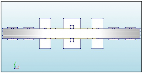
In this research, a finite element model was employed to investigate a multi-span bridge that traversed the Songhua River in the Northeast of China. The model constructed with DIANA software, a computer code that executes complex calculations, is demonstrated in Figure 2.
4.2 Mesh and element types
The soil, piles, and pier are discretized into finite elements to accurately represent their geometry and material properties. The mesh consists of 8-node solid elements for the soil and beam elements for the bridge components. The soil is modeled using 8-node hexahedral solid elements. These elements are chosen for their ability to accurately capture the nonlinear behavior of soil under dynamic loading conditions. The piles are represented using beam elements, which are suitable for capturing the bending and axial behavior of slender structural members. The pier is also modeled using beam elements to accurately depict its structural response under dynamic loads.
(a) Bridge concrete members
(b) Front view of bridger member, water, and soils layers
Figure 2. The finite element mesh of the prototype
4.3 Boundary conditions
The 3D time-domain viscoelastic artificial boundary has been introduced as the boundary of the size of the soil domain, which ensures that there are no reflections of seismic waves at the boundaries and hence results in the best connection between soil and structure. The bottom of the soil domain is interpreted as the top surface of the bedrock with a shear wave velocity greater than 500 m/s. Viscoelastic boundaries are applied at the sides of the soil domain to confine the domain and thus facilitate the simplified connection between soil and structure.
4.4 Loads and analysis settings
The model incorporates seismic ground motion as input to simulate the earthquake effects. The acceleration time history of the ground motion is applied at the base of the soil domain. The forces due to water currents and waves are included in the model. These hydrodynamic forces are calculated based on the relative motion between the water and the structure, as detailed in the governing equations section.
4.5 Material models
The dynamic plastic-damage model represents the concrete bridge members. This model captures the nonlinear behavior and damage buildup in concrete under cyclic loads. The dynamic nonlinearity of the soil is characterized by the viscous-plastic memorial nested yield surface model. Since Poisson's ratio is assumed to be 0.49 with the conviction that soil was saturated and undrained at the time of the earthquake.
4.6 Mesh convergence
Mesh convergence is a crucial step to ensure the accuracy of the finite element analysis. A series of simulations with progressively refined meshes are conducted to verify that the results are independent of the mesh size. The following steps are taken for mesh convergence:
Initial Mesh: An initial coarse mesh is generated to capture the general behavior of the system.
Refined Meshes: The mesh is progressively refined, particularly in regions with high stress gradients such as the pile-soil interface and the vicinity of the pier.
Convergence Criteria: The results, such as displacement, stress, and strain, are monitored to ensure that further refinement of the mesh does not significantly alter the results.
4.7 Model validation
The validation of the finite element model is performed by comparing the simulation results with available experimental data and analytical solutions. The following steps are taken for validation:
(1) The dynamic response of the model is compared with experimental results from shaking table tests or field measurements of similar bridge structures;
(2) The results are also compared with analytical solutions or simplified models to ensure that the finite element model accurately captures the fundamental behavior of the system;
(3) A sensitivity analysis is conducted to examine the effect of varying material properties and boundary conditions on the results, ensuring that the model is robust and reliable.
Here are the key aspects of the validation process:
4.7.1 Benchmarking against simplified models
The finite element model results were compared against simplified analytical models commonly used in geotechnical engineering for seismic and hydrodynamic analysis. Simplified models such as single-degree-of-freedom (SDOF) systems or equivalent linear models were employed to verify the trends and magnitude of displacements, accelerations, shear forces, and moments.
4.7.2 Comparison with published experimental data
The computational results were benchmarked against experimental data from published studies that investigated similar bridge piers under seismic and hydrodynamic loading. Experimental data included measurements of pier displacements, accelerations, and internal forces recorded during shaking table tests or field observations.
4.7.3 Validation criteria
Validation criteria included quantitative comparison of peak displacements, accelerations, shear forces, and moments between the computational model and experimental data. Statistical measures such as root mean square error (RMSE), correlation coefficient (R²), and percentage difference were used to assess the agreement between model predictions and experimental results.
4.8 Model sensitivity and mesh convergence
Sensitivity analyses were conducted to examine the influence of key parameters such as soil properties, pile characteristics, and loading conditions on the model predictions. Mesh convergence studies were performed to ensure that the finite element mesh resolution was adequate to capture the complex behavior of the soil-pile-structure system under dynamic loading.
The model's limitations and speculations are then assessed and validation results are presented. The differences between the predicted results and the experimental results are further scrutinized in order to identify areas that may be improved by the model or its specifics. This validation exercise demonstrates that the computational model can effectively predict the behavior of bridge piers during an earthquake and underwater pressure. The authors promose that the proposed methodology can be employed to assess the structural behavior of bridge piers in complex environmental conditions using simplified models and observed data, as listed in Table 2.
The above-described finite element modelling technique offers a thorough and repeatable way to predict the dynamic response of bridge structures to hydrodynamic and seismic forces. The research guarantees the accuracy and dependability of the findings by completing mesh convergence and model validation, as well as by carefully describing the mesh, element types, boundary conditions, loads, and analysis settings. Enhancing the seismic resilience of bridge structures and expanding our knowledge of the behaviour of deepwater pile foundations depend on this thorough modelling technique.
Table 2. Comparison of computational model predictions with experimental data
|
Loading Condition |
Parameter |
Computational Model Prediction (mm or m/s²) |
Exp. Data (mm or m/s²) |
|
Earthquake only |
Peak displacement (relative) |
28.3 mm |
27.9 mm |
|
Peak acceleration (top of pier) |
7.1 m/s² |
6.8 m/s² |
|
|
Earthquake + Current-wave |
Peak displacement (relative) |
34.2 mm |
32.5 mm |
|
Peak acceleration (top of pier) |
9.2 m/s² |
8.9 m/s² |
The model replicates the exact dynamic response of the bridge pier to the interaction of waves, the water current's velocity potential, and ground motion resulting from seismic waves. Table 3 provides data on the characteristics of currents and waves expected over a 100-year period at the location. It focuses solely on the transverse (y-axis) alignment of the bridge regarding water loads from currents and waves. For every simulation conducted, the initial water level was set at 12 meters. If the Environment Conditions and Load Standard indicate that CD=1.2, CM=2.0, and CA=1.0.
Table 3. Current-wave parameters
|
Parameter |
Value |
|
Return Period (Years) |
100 |
|
Current Velocity (m/s) |
2.5 |
|
Wave Height (m) |
0.5 |
|
Wave Period (sec) |
4.5 |
|
Wavelength (m) |
8.5 |
|
Wave Velocity (m/s) |
4.5 |
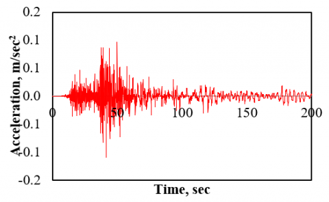
Figure 3. The acceleration time history of November 2017, Halabjah earthquakes in Baghdad
In this research, the progression of acceleration at the Halabjah earthquake that occurred in Baghdad on November 12th, 2017 is employed as the seismic input to simulate the response of the model structure. The initial accelerometer demonstrates that the total time course of ground excitation is 200 seconds and has a peak value of 0.11 g at 41.5 seconds. Figure 3 illustrates the progression of the horizontal component of this seismic stimulation. To investigate the effect of different earthquake motions with different peak accelerations, three different frequencies (20 Hz, 40 Hz, and 60 Hz) are used.
6.1 Displacement and acceleration response of the pier
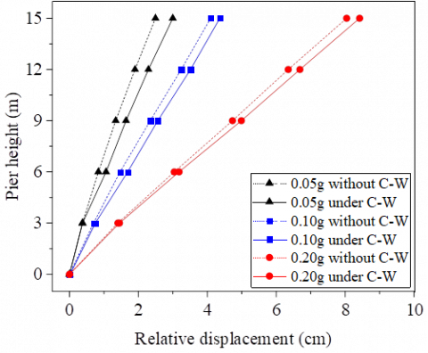
Starting with the displacement between the base of the pier and the absolute acceleration at the top of the pier, which is an important indicator of the structural integrity of the pier. The relative displacement of the top of the pier with respect to the base of the pier is a key factor in the seismic deformation analysis in the seismic design of the pier. The main relative motion caused by rock movement is affected by the absolute acceleration of the pier tip caused by the cap movement. Figure 4 shows the relative displacement of the pier along with the peak accelerations (0.05 g, 0.10 g, and 0.20 g), which may or may not be caused by earthquake ground motion, water current and waves.
It can be seen that the fluctuation of the hydrodynamic pressure level affects the tip displacement response relative to the reactivity of the pier tip, reaching a maximum value near the pier tip. Therefore, the hydrodynamic pressure increases the reactivity of the pier, resulting in a gradual increase in the relative displacement of the top of the pier with respect to the base of the pier. This behavior is observed when both current waves and seismic activity are included, rather than the case where only earthquakes are considered. Between 0.05 g and 0.20 g, the trend shows an increase for input accelerations. As shown in Figure 4(a), the maximum relative displacement of the pillar caused by the flow wave increases when the input acceleration is 0.05 g, while the effect of the flow wave decreases when the input acceleration is 0.10 g and 0.20 g.
The bottom of the pier is subjected to seismic stress, which causes concrete cracking and the formation of plastic hinges, resulting in a decrease in bending stiffness at this location, leading to lower acceleration but larger relative displacement. At the same time, the top of the pier is subjected to significantly higher acceleration due to the inertial effect of the taller structure; however, Figure 4(b) shows that the acceleration at the top and end of the column remains constant.
Therefore, it is clear that the combined effect of the earthquake and the current wave at the top of the pier causes a much smaller acceleration than the acceleration generated by the earthquake alone.
(a)
(b)
Figure 4. Relative displacement and acceleration responses of the bridge pier [26]
6.1 Internal force response of the pier
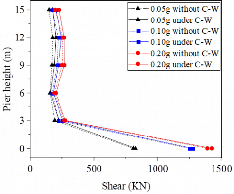
The potential for a plastic hinge is found at the lowest section of the single-column pier. Therefore, to understand the impact of the internal forces on the pier, it is essential to analyze the shear forces and moments at the base of the pier under the influence of earthquake action and current-wave-shock loads, particularly as defined by the hydrodynamic pressure during an earthquake. Damage to the pier resulting from an earthquake creates a plastic hinge, as the response values of internal forces exceed the bearing capacity in a specific segment.
As illustrated in Figure 5, the shear force and the moment of the pier is evident. It is immediately apparent that the shear force at the footing significantly exceeds that observed higher up. This indicates that the development of any plastic hinge at this location will be relatively straightforward, given that the stress at the footing is considerably higher than in the upper sections. This confirms that the moment at the pier's base within a 6 m range is greater at this point compared to other locations. The piling body is unaffected by the waves when the current waves do not impact it, as the acceleration at the 0.05 g level is also applied while the waves remain within the piling structure.
(a)
(b)
Figure 5. Shear force and moment responses of the bridge pier [26]
Hydrodynamic pressure could influence the base of the piers, where a plastic hinge region is easily formed following an earthquake. When designing piers for seismic activity in deep water, it is essential to take into account the impacts of current waves. The full strength of the steel may be effectively utilized; additionally, the longitudinal steel extension of the pier could be more securely anchored to the cap or capping beam, among other considerations. These factors may help address the effects of hydrodynamic pressure on the seismic design of the pier. To restrict the horizontal displacement of the core concrete, small-spaced round or spiral stirrups might be employed.
6.2 Earthquake hydrodynamic pressure influence coefficient
The coefficient of hydrodynamic pressure, K, is determined by the maximum dynamic response of the pier head to the combined influence of current and wave action. It is calculated using the formula: K = (peak value of dynamic response under combined wave and current effects minus peak value of dynamic response under earthquake alone) / (peak value of dynamic response under earthquake alone) × 100%.
The coefficients for hydrodynamic pressure effects related to shear force, moment, relative displacement, and acceleration at both the top and bottom of the pier are denoted as Kd, Ka, Ks, and Km, respectively. Even if the influence pattern is not as apparent, the hydrodynamic pressure's impact on the dynamic response peak of bridge piers could significantly affect seismic wave inputs and peak acceleration. The acceleration effect reached a peak of 11%, while the influence on relative displacement was minimal; the effects on shear and moment were roughly 4%, and the average impact remained fairly consistent. This emphasizes how the characteristics of earthquake ground motion affect the dynamic response of the pier to wave-current interactions.
While the results presented are extensive, the discussion lacks depth in interpreting these results in the context of existing knowledge. Here, we provide a more detailed analysis of the findings, compare them with empirical data and other numerical simulations, and discuss their broader implications.
7.1 Displacement and acceleration analysis
Two key engineering criteria for the structural performance of a bridge pier are the top displacement concerning the pier's bottom and the average acceleration at the pier's top. The top displacement in relation to the bottom is the most vital factor in the pier's seismic design, as it has a direct effect on structural integrity. Additionally, it governs how seismic excitation influences the movement of the bridge deck, rendering it equally important.
The response of the pier is affected by hydrodynamic pressure from current waves, which reaches its maximum near the top. Consequently, the relative displacement during both current-wave and seismic occurrences exceeds that experienced during seismic actions alone. This trend suggests that relative displacement is more responsive to lower levels of acceleration, decreasing from input acceleration values of 0.05 g to 0.20 g. These findings align with the research conducted by Moazam et al. [3], which demonstrated that hydrodynamic forces significantly impacted the structural responses to seismic events.
7.2 Internal force response
The shear force and moment at the pier base are an order of magnitude higher than those at the top, based on an internal forces study. Therefore, the bottom part becomes more prone to developing plastic hinges because of an earthquake shock. These values are again comparable with previous numerical calculations and real findings work such as in reference [29] where the bottom pier was proved very susceptible to seismic forces due to higher concentrations of stresses.
This is an indication that the hydrodynamic pressure does affect the shear force and moment responses, but it is more visible at the higher accelerations. This underscores the imperative need for rigorous seismic design that incorporates two impacts, hydrodynamic and seismic forces combined, especially when the structure is in deep water, where both forces play a more significant role.
7.3 Comparisons with empirical data
Comparison of empirical data from past earthquakes, including the 2011 Tohoku earthquake, shows similar responses of bridge piers under the dynamic impact of seismic and hydrodynamic loads. Also, findings [12] in empirical studies already exist, which reported increased displacements and internal stresses in bridge piers due to hydrodynamic forces.
The dynamic response of bridge piers to combined seismic and hydrodynamic loadings was evaluated in this work using a comprehensive finite element model. In addition to the nonlinear behaviour of soil plus concrete, the Halabjah earthquake excitation, the Morison hydrodynamic pressure formula, and current-wave effects on pile foundation bridge piers were accomplished. Below is a discussion of the study's limitations, the results and their wider implications, and potential future research approaches. The key findings are shown as follows:
1. When current, waves, and earthquakes all work together, the pier's relative peak displacement is greater than when the seismic effect acts alone. This emphasises how crucial hydrodynamic forces are to the structural reaction during seismic activity.
2. The combined effect of waves and currents had a greater effect on relative displacement than on acceleration. Shear force and moment owing to hydrodynamic pressure have equally significant effects, proving that these forces should not be disregarded in the design and study of bridge structures.
3. The results indicate that in order to guarantee the safety and dependability of pile foundation bridge piers in maritime settings, the impacts of both current and wave loads must be taken into account during the seismic design process.
4. The dynamic response of the pier to the stresses is considerably affected by the types of ground movements of earthquakes. This unambiguously highlights the necessity for a site-specific seismic investigation in bridge design.
The results of this research have various larger implications for the design and safety evaluation of bridge structures:
1. By revealing the enormous influence of hydrodynamic pressures on bridge piers during earthquakes, this work highlights the need of considering these forces in seismic design to promote structural resilience.
2. The research offers useful insights that may inspire the creation of more robust design guidelines and standards for bridges in coastal and offshore settings, contributing to increased infrastructure safety.
While the study provides important insights, it also has several limitations:
1. The Morison hydrodynamic pressure formula used in this study is a simplified model. Future research should explore more complex and accurate representations of hydrodynamic forces.
2. The material models for soil and concrete, while sophisticated, still involve assumptions that may not fully capture the real-world behavior of these materials under extreme conditions.
The paper provides a comprehensive analysis of the dynamic response of piershafts subjected to combined hydrodynamic forces and seismic impacts, serving as a foundational reference for the design and safety of bridges in maritime settings. To address the identified limitations and effectively incorporate findings to improve infrastructure resilience against extreme environmental loads, establish and disseminate guidelines with prioritised criteria for climate resilience in infrastructure planning. The guidelines must be applicable to the design of structures in coastal and seismic regions, incorporating specified design parameters for particular construction techniques addressing earthquake and hydrodynamic forces. This ultimately leads to a substantial contribution to SDG 13 on Climate Action by enhancing resilience to climate-related threats and promoting sustainable development in at-risk regions.
[1] Huang, S., Liu, C. (2024). Dynamic behavior analysis of bridge pier under impact of dam-break flood in different directions. Natural Hazards, 120(3): 2705-2730. https://doi.org/10.1007/s11069-023-06301-6
[2] Yazdani, M., Jahangiri, V., Marefat, M.S. (2019). Seismic performance assessment of plain concrete arch bridges under near-field earthquakes using incremental dynamic analysis. Engineering Failure Analysis, 106: 104170. https://doi.org/10.1016/j.engfailanal.2019.104170
[3] Moazam, A.M., Hasani, N., Yazdani, M. (2018). Incremental dynamic analysis of small to medium spans plain concrete arch bridges. Engineering Failure Analysis, 91: 12-27. https://doi.org/10.1016/j.engfailanal.2018.04.027
[4] Li, Z.X., Zheng, Q., Su, J., Shi, Y., Zhao, B. (2023). Underwater shaking table tests of a sea-crossing cable-stayed bridge under combined earthquake and wave action. Ocean Engineering, 287: 115871. https://doi.org/10.1016/j.oceaneng.2023.115871
[5] Yamada, Y., Kawano, K., Iemura, H. (1988). Wave and earthquake response of offshore structures with soil-structure interaction. The Japan Society of Civil Engineers, 1988(398): 157-166. https://doi.org/10.2208/jscej.1988.398_157
[6] Karadeniz, H. (1999). Spectral analysis of offshore structures under combined wave and earthquake loadings. In ISOPE International Ocean and Polar Engineering Conference. ISOPE-I-99-421.
[7] Fukusumi, T., Uchida, N., Uchida, D. (2003). Response characteristics of soft settled type of offshore structures subjected to harmonic sea wave and earthquake wave. In ISOPE International Ocean and Polar Engineering Conference. ISOPE-I-03-149.
[8] Etemad, A.K., Gharabaghi, A.R.M., Chenaghlou, M.R. (2004). Nonlinear dynamic behavior of fixed jacket-type offshore platforms subjected to simultaneously acting wave and earthquake loads. In International Conference on Offshore Mechanics and Arctic Engineering, Vancouver, British Columbia, Canada, pp. 893-900. https://doi.org/10.1115/OMAE2004-51498
[9] Abbasi, M., Gharabaghi, A.R.M. (2007). Study the effect of wave directionality on dynamic nonlinear behavior of jack-up subjected to wave and earthquake loading. In International Conference on Offshore Mechanics and Arctic Engineering, San Diego, California, USA, pp. 377-384. https://doi.org/10.1115/omae2007-29350
[10] He, X.Y., Li, H.N. (2007). Research on piles with small dimension under the combination of seismic and wave action. Journal of Earthquake Engineering and Engineering Vibration, 27(5): 139-145.
[11] Alsultani, R., Saber, Q.A., Al-Saadi, A.A., Mohammed, O.I., Abed, S.M., Naser, R.A., Hussein, A., Muslim, F., Fadhil, H., Karim, I.R., Khassaf, S.I. (2014). The impact of climate change on the reinforcement durability of concrete bridge structures. The Open Civil Engineering Journal, 18: e18741495337012. http://doi.org/10.2174/0118741495337012240812105905
[12] Song, B., Zheng, F., Li, Y. (2013). Study on a simplified calculation method for hydrodynamic pressure to slender structures under earthquakes. Journal of Earthquake Engineering, 17(5): 720-735. https://doi.org/10.1080/13632469.2013.771592
[13] Wei, C., Zhou, D., Ou, J. (2019). Wave and wave-current actions on a bridge tower: An experimental study. Advances in Structural Engineering, 22(6): 1467-1478. https://doi.org/10.1177/1369433218816523
[14] Huynh, L.E., Chu, C.R., Wu, T.R. (2023). Hydrodynamic loads of the bridge decks in wave-current combined flows. Ocean Engineering, 270: 113520. https://doi.org/10.1016/j.oceaneng.2022.113520
[15] Moosavian, S.H., Karimpour, S., Pantazopoulou, S.J. (2024). Comparative analysis of hydrodynamic loads on bridge piers: Assessing standards through numerical modeling. Canadian Journal of Civil Engineering. https://doi.org/10.1139/cjce-2024-0145
[16] Lu, Y., Liu, Z., Xu, W. (2024). Research progress and prospects on pier-type submerged floating tunnels. Ocean Engineering, 308: 118187. https://doi.org/10.1016/j.oceaneng.2024.118187
[17] Zhu, H., Chen, Y., Liu, L. (2022). Dynamic responses of bridges under catastrophic floods considering fluid–soil–structure interactions. Engineering Failure Analysis, 140: 106596. https://doi.org/10.1016/j.engfailanal.2022.106596
[18] Xu, G., Cai, C.S. (2015). Numerical simulations of lateral restraining stiffness effect on bridge deck–wave interaction under solitary waves. Engineering Structures, 101: 337-351. https://doi.org/10.1016/j.engstruct.2015.07.031
[19] Qu, K., Yao, W., Tang, H.S., Agrawal, A., Shields, G., Chien, S.I., Chiodi, I. (2021). Extreme storm surges and waves and vulnerability of coastal bridges in New York City metropolitan region: An assessment based on Hurricane Sandy. Natural hazards, 105: 2697-2734. https://doi.org/10.1007/s11069-020-04420-y
[20] Afan, H.A., Mohtar, W.H.M.W., Khaleel, F., Kamel, A.H., Mansoor, S.S., Alsultanie, R., Ahmed, A.N., Sherif, M., El-Shafie, A. (2024). Data-driven water quality prediction for wastewater treatment plants. Heliyon, 10(18): e36940. https://doi.org/10.1016/j.heliyon.2024.e36940
[21] Li, T., Lin, J., Liu, J. (2024). Analysis of time-dependent seismic fragility of the offshore bridge under the action of scour and chloride ion corrosion. Structures, 28: 1785-1801. https://doi.org/10.1016/j.istruc.2020.09.045
[22] Ministry of Communications of China. (2007). Code for design of ground base and foundation of highway bridges and culverts. JTG D63-2007, China Communications Press, Beijing (in Chinese).
[23] Yun, G., Liu, C. (2024). Study on the hydrodynamic effects of bridge piers under velocity-type pulse ground motion based on different characteristic periods. Applied Sciences, 14(22): 10709. https://doi.org/10.3390/app142210709
[24] Lee, J.Y., Kim, S.W., Mansour, M.Y. (2011). Nonlinear analysis of shear-critical reinforced concrete beams using fixed angle theory. Journal of Structural Engineering, 137(10): 1017-1029. https://doi.org/10.1061/(asce)st.1943-541x.0000345
[25] Wu, H., Liu, X., Cheng, Y.H., Chen, T.L. (2024). Dynamic behaviors of bridges with corroded RC piers under barge collisions. Engineering Structures, 319: 118843. https://doi.org/10.1016/j.engstruct.2024.118843
[26] Alsultani, R., Karim, I.R., Khassaf, S.I., Ashor Al-Saadi, A. (2024). Dynamic response analysis of coastal bridge members exposed to water forces and earthquakes. IntechOpen. https://doi.org/10.5772/intechopen.1006514
[27] Thair, J.M., Imad, A.D., Riyadh, A.A. (2018). Experimental determination and numerical validation of the chloride penetration in cracked hydraulic concrete structures exposed to severe marine environment. IOP Conference Series: Materials Science and Engineering, 454(1): 012099. https://doi.org/10.1088/1757-899X/454/1/012099
[28] Zhou, H., Fan, X.P., Liu, Y.F. (2024). Dynamic serviceability and safety reliability analysis of aging PC girder bridges with non-prestressed reinforcement considering concrete shrinkage, creep and stochastic vehicle load flows. Structures, 64: 106515. https://doi.org/10.1016/j.istruc.2024.106515
[29] Al-Taie, A.J., Albusoda, B.S. (2019). Earthquake hazard on Iraqi soil: Halabjah earthquake as a case study. Geodesy and Geodynamics, 10(3): 196-204. https://doi.org/10.1016/j.geog.2019.03.004