Farhad Hosseinlou![]() | Ali Tarar Bazony
| Ali Tarar Bazony![]() | Mojtaba Labibzadeh
| Mojtaba Labibzadeh![]() | Kadhim Z. Naser*
| Kadhim Z. Naser*![]()
© 2025 The authors. This article is published by IIETA and is licensed under the CC BY 4.0 license (http://creativecommons.org/licenses/by/4.0/).
OPEN ACCESS
In this study, the behavior of concrete filled double skin steel tubular (CFDST) composite columns with various cross-sections and reinforcements under explosive loads was investigated. Five column models, each 5 meters in length with an inner diameter of 50 cm and an outer diameter of 80 cm, were simulated using ABAQUS/Explicit software. Column 1 had no reinforcement, Column 2 included four linear reinforcements, Column 3 had four square reinforcements, Column 4 combined linear and square reinforcements, and Column 5 featured trapezoidal reinforcements. Explosive loading equivalent to 250 kg of TNT was applied at different distances, with an optimal distance of 4.5 meters identified for all models. Additionally, a 30×10-meter bridge model, resembling a bridge in Basra, was simulated using the weakest (Column 1) and strongest (Column 5) columns. Explosions were analyzed for scenarios above the bridge and below the columns. The results demonstrated that Column 5 significantly outperformed Column 1 in resisting stresses, tensile and compressive damage, and displacements. In the scenario with explosions beneath the bridge, the performance of the bridge with Column 5 improved by up to 40%. Furthermore, tensile damage in the concrete was found to be considerably greater than compressive damage, underscoring the necessity of reinforcing concrete against tensile forces. The CFDST columns for bridge is found be the most effective among in reducing the dynamic effect induced by the blast loading on the structure.
columns, bridges, CFDST, blast load, ABAQUS, explosive loading, simulation, compression damage, tensile damage
Bridges are an important part of the physical infrastructure in most countries. They play a crucial role in the transportation of people and goods, serving as an economic and financial social asset. Considering that bridge columns are one of the most critical components of bridges and are more exposed to explosions, damage to them leads to damage to the bridge itself. As a result, this can disrupt intercity and urban transportation, causing traffic, problems, and economic and financial losses. Due to these reasons and the importance of damage to bridge columns from explosions, many researchers and engineers have focused on designing bridges to withstand explosive loads.
Over the past 60 years, more than 550 terrorist attacks have been carried out against bridges and infrastructure systems [1]. Explosions on road bridges may occur unintentionally or deliberately as part of an attempt to disrupt the transportation network. Given that bridges are vital parts of infrastructure and key points in traffic flows and are easily accessible, protecting them is extremely challenging. This makes these structures potential targets for explosive and terrorist attacks. Bridge columns are primary load- bearing members in structures and bridges and are vulnerable to terrorist attacks and explosive loads [2]. In this regard, several studies have been carried out in the last years towards the fulfillment of optimal design approaches for columns exposed to combined gravity and wind loads, as well as accidental impacts like blast [3-9]. And more efforts were also made to protect infrastructure from the risk of explosion [10-13]. In order to benefit from the advantages provided by both steel and concrete to obtain high resistance that can handle large blasting loads, this study examines composite columns of the CFDST type, which are 5 meters long with an inner diameter of 50 cm and an outer diameter of 80 cm, in which the type of reinforcements used in the columns varies, against explosive loads. The explosive load is applied to the columns at specified distances to determine the appropriate distance with a weight of 250 kilograms.
Figure 1. Representing the bridge similar to a model in the center of Basra city
After reviewing the results and selecting column 1 as the weakest and column 5 as the strongest, a semi-realistic bridge is simulated using the characteristics of the Bridge in the center of Basra Province as shown in the Figure 1, employing the modeled columns from the previous section (preferably columns 1 and 5) as the bridge columns. Subsequently, the explosive load is applied at a distance of 1 meter from the columns, along with the axial load resulting from the weight on the bridge, and the results from the analyses are examined and compared.
Considering that bridges and the columns used in them are essential components of a country's infrastructure, and are utilized for the transportation of people and traffic flows both within and outside cities, explosions and terrorist attacks targeting bridge columns can lead to significant financial and economic damages. Therefore, it is of utmost importance to use modern methods such as regular and reinforced columns, as used in this research, to mitigate the explosive behavior and damage to bridge columns, taking advantage of the good advantages provided by both steel and concrete together.
AL-Thairy [14] studied the numerical simulation of the behavior and failure patterns of steel columns under blast loads using the dynamic finite element package ABAQUS/Explicit. The conclusions extracted from this parametric study may be used to develop a thorough understanding of the behavior and failure of steel columns subjected to blast load which, in turn, could lead to a more accurate practical design procedure. Nassr et al. [15] studied the dynamic response of steel columns. Exposed to blast loading, 13 typical steel columns were tested and bored, each carrying a central load equal to 25% of its pivotal capacity, using live explosives, including a shipment size between 50 and 250 kg of ammonium nitrate/fuel oil (ANFO) and a terrestrial confrontation distance from 7.0 to 10.3 meters. The results showed that in the columns that show a flexible response, due to the elongation of the shaking period of the pivotal load, the side deformation caused by the explosive load is reduced instead of amplifying it by pivotal pregnancy. Nawar et al. [16] studied the dynamic performance of perforated steel columns (PSCs) at numerical assessment under different levels of explosion threats using LS-DNA software. Six models of the columns shown in the geometric shapes under different properties of pregnancy were taken from the bombing of the material ANFO which is a high- explosive substance with most of its composition quantities range from 50 kg to 250 kg, the results showed that an indicator the damage is less in the case of the fixed end of it in the free end, as well as the more pinned end the more damaged indicator.
In the study conducted by Li et al. [17], the contact explosion was studied numerically and experimentally against double-casing steel columns (CFST) and three samples of circular columns were taken and field tests were conducted where various damage patterns were detected during the explosions. Arbitrary-Lagrangian-Eulerian (ALE) formulations connected in pairs with fluid-structure interaction (FSI) algorithms that are obtainable in the explicit nonlinear dynamic analysis program LS- DYNA were used to improve the numerical models. The explosives were placed adjacent to the columns with material TNT and in the quantity from 0.6 kg to 1 kg. As reported by Zhang et al. [18], numerical studies have been conducted to investigate the bending behavior of CFST columns under both fixed and dynamic loads. The results indicated that CFST columns showed good resistance against bending loads under fixed and dynamic loading conditions, and they can be them widely in these areas where possible explosive attacks or frequent earthquakes are expected. Ahmad et al. [19] examined the local and overall buckling of square CFDST columns filled with high-strength concrete. They proposed a new mathematical model for simulating slender square CFDST columns and developed a formulation for local and overall buckling, taking confinement into account. Hosseinian et al. [20] investigated the overall behavior of circular CFDST columns with an outer layer of stainless steel in 2017. They used ordinary steel for the inner layer and stainless steel for the outer layer. They found that these columns had lower costs and less weight compared to conventional columns while maintaining high strength. Elchalakani et al. [21] conducted finite element simulations of short circular CFDST columns under axial compressive loads in 2019. Li et al. [22] investigated the post-buckling behavior and residual capacity of CFDST columns subjected to explosive loading in 2020. They developed a numerical model to analyze the explosive behavior of these capacity under explosive loading. Yan and Zhao [23] investigated the compressive strength of short, double- walled, concrete-filled steel tubes with circular cross-sections under axial loading. They noted that internal and external confinement in CFDST columns significantly affects their compressive strength and ductility. Alberto et al. [24] investigated the behavior of slender double-walled steel columns under non-axial loads. They compared their findings with analytical formulas from other studies. Li et al. [25] investigated the experimental and numerical behavior of CFDST columns under near-explosion loading. The concrete core was severely damaged, while the steel sections remained largely intact, except for limited areas close to the explosion. The energy absorption rates of the different sections of the CFDST column showed that severe plastic damage to the concrete core plays a significant role in energy absorption under near- field explosions. Momeni et al. [26] found that the proposed formulas can provide a good level of accuracy and high computational efficiency for steel columns of H section loaded by blasting. In addition, the damage index was linked to the conventional displacement/rotation index. According to Xia et al. [27], the dynamic behavior of precast concrete-filled double-layer steel pipe sectional columns (PS-CFDST) under blast loads was investigated. Field tests were conducted on three large columns subjected to large equivalent blasts and a high-precision finite element model was used to study the behavior of this type of columns under blast. The numerical model was validated against the experimental test results. It was observed that the dynamic response of these columns is divided into two stages: shear deformation stage and bending deformation stage. It was found that shear deformation absorbs most of the blast energy through damage to the concrete and the outer steel pipe. The self-centering ability of PS tendons is mainly characterized in the bending deformation stage. Li et al. [28] investigated the seismic performance of columns CFDST by experimental means after field explosion, where two samples of circular columns and two samples of square columns were tested, each with similar axial load carrying capacities. The evaluation of the results shows that the columns damaged by explosion retain good lateral strength and energy dissipation capacity, which indicates the elastic performance of CFDST columns in a post-explosion earthquake scenario. It was also observed that the post-explosion seismic performance is more affected in the direction of loading towards the side of the explosion. Mi et al. [29] studied the cases in which columns can be subjected to coupled collision and blast (CCB), and the reliability of the numerical model was verified on the basis of the existing experimental results. Then the damage propagation process of this type of columns subjected to separate impact and blast loads was investigated. The damage history patterns, deflection D and impact force F were comparatively analyzed, and the performance level of columns after CCB loads was determined based on damage index thresholds. The main factors affecting the dynamic behavior of columns were investigated, and the result showed that compared with the sum of deflections under separate impact and residual deflection under CCB loads increased by 6.1 and 7.8 respectively. Gangolu and Gisaro [30] In this study, two profiles of Steel Wide-Flange were taken for far axial blasts on the weak axis. Two profiles of steel W200×71 and W150×24 were taken using as a finite element tool. The simulation included axial load ratio 0, 20%, 40%, 60%, 80% under different blast pulses. Two experimental models were taken to validate the numerical methodology. The simulations found a significant Axial Load Ratio (ALR) on the response of the profile for identical blast profiles leading to elastic behavior, plastic deformation, or failure scenarios. The damage index Di was calculated. The relationship between ALR and Di provides insights for building shape decisions and modification options which is critical for structural safety. Some researchers have addressed this topic from different perspectives such as Yang et al. [31], Yimer and Dey [32], Gao et al. [33], and Khalaf et al. [34].
The aim of this study is to investigate the behavior of CFDST composite columns with various sections and reinforcements under explosive loads and to propose strategies for enhancing the resilience of infrastructure, particularly bridges, against explosion-induced damages. The research employs precise simulations of both reinforced and non-reinforced columns using ABAQUS software to analyze the impact of explosive loads at different distances. The innovations of this study include the design and evaluation of new reinforced CFDST models, detailed analysis of stresses and displacements in columns and bridges, and an emphasis on the necessity of reinforcing concrete against tensile stresses. The findings provide a foundation for optimizing the design of explosion-resistant columns and bridges to minimize economic and financial losses in infrastructure. The importance of the study lies in the fact that it deals with the representation of a semi-real bridge with large dimensions and the effect of blast loading on it, unlike most studies that mostly deal with the simulation of small models of CFDST columns.
In this section, the explosion simulation on a CFDST column is conducted using the Conwep feature in the ABAQUS software. The geometry and modeling conditions for this case are fully presented below, and the specifications of the model are extracted and used from the reference [17].
2.1 Validation model
The column studied in this research is of the CFDST type, consisting of two steel tubes, with concrete filling the space between these two tubes. The specifications of the model and its dimensional parameters are provided in Figure 2 and Table 1.
Figure 2. Geometry of validation model [17]
Table 1. Specifications of validation model [17]
|
Model Name |
H (mm) |
Dxt (mm) |
Dxt (mm) |
Hd (mm) |
TNT (kg) |
|
CB1 |
2500 |
159×6 |
325×6 |
300 |
1 |
|
CB2 |
2500 |
159×6 |
325×7 |
300 |
0.6 |
|
CB3 |
2500 |
159×6 |
325×8.5 |
300 |
0.6 |
In Table 1, Hd refers to the distance of the explosive charge from the top of the foundation. Based on the mentioned details, the concrete section, inner steel tube, and outer steel tube were modeled in the ABAQUS software, with a schematic representation shown in Figure 3.
The material used for the concrete section is concrete with a maximum compressive strength of 40 MPa. Additionally, the steel used in the inner and outer tubes is Q345 steel, the material properties of which are provided in Table 2. A schematic of the assembly model for Validation Model is presented in Figure 4.
The inner and outer steel tubes were connected to the inside and outside of the concrete section using the Tie constraint. According to the constraints provided in the reference article [17], the upper and lower sections of the column are fully fixed. The explosive charge, equal to 1 kg, is defined using Conwep in ABAQUS software, and select the TNT definition menu in ABAQUS as incident wave (surface blast), and is applied to the outer surface of the model at a height of 300 mm from the foundation. The type of mesh used for the concrete section and foundation is C3D8R, which is an 8-node three-dimensional mesh. For the steel sections, the S4R mesh, a 4-node shell mesh, is employed, with a mesh size of 20 mm selected. In this section, the results related to Validation Model are presented. The first result obtained pertains to the displacement caused by the explosion of a 1 kg mass in sample CB1. In the reference [17], this displacement is reported as a circular area with a diameter of 150 mm and a depth of 85 mm, with a schematic representation shown in Figure 5. The results obtained from ABAQUS are presented in Figure 6.
Figure 3. Geometry of the inner and outer steel tubes and the internal concrete section and foundation in validation model
Table 2. Material properties for validation model [6]
|
Material |
E (GPa) |
v |
fc (MPa) |
Yield Stress (MPa) |
Ultimate Stress (MPa) |
|
Concrete |
29 |
0.2 |
40 |
- |
- |
|
Steel |
200 |
0.3 |
- |
220 |
345 |
Figure 4. Assembly model of validation model
Figure 5. Results obtained for field observation of specimen and model CB1 in reference [17]
Figure 6. Results obtained from the analysis
Table 3. Comparison between experimental data paper reference and resulting ABAQUS [6]
|
Specimen |
Experimental Data |
Resulting Data from ABAQUS |
||||
|
D1 (mm) |
D2 (mm) |
Dp (mm) |
D1 (mm) |
D2 (mm) |
Dp (mm) |
|
|
CB1 |
150 |
150 |
85 |
158 |
136 |
86 |
|
CB2 |
140 |
120 |
30 |
158 |
115 |
28 |
|
CB3 |
140 |
120 |
25 |
158 |
115 |
24 |
Table 3 represents a comparison between the experimental data and the results obtained from ABAQUS. In this table, D1, D2, DP was width, length, depth of the hole due to explosion respectively and the experimental results of the pit dimensions for the three models were compared with the results extracted after representing the three models using the ABAQUS program, where a 1 kg detonation charge of Tinti was used with the first model and 0.6 kg with the second and third models. The table shows a clear convergence between the experimental results and those corresponding to them from the ABAQUS program. It is also noted that the pit depth for Model 3 is less than its depth for Model 3, and this is due to the fact that the thickness of the outer shell for Model 3 is greater than the thickness in Model 2. From the above results, we conclude that it is possible to rely on representing columns of this type using ABAQUS
As observed, the results obtained from the ABAQUS analysis are 86 mm, which shows a 2% difference compared to the result presented in reference [17], which is 85 mm. This indicates that the results are acceptable with good accuracy.
2.2 Simulation of CFDST studied columns under explosive load
In this section, five CFDST columns are modeled in ABAQUS and subjected to explosive loading. The explosive load is applied using utilizing the Conwep feature in ABAQUS. The models feature a concrete section with an internal diameter of 500 mm and an external diameter of 800 mm, surrounded by two steel tubes with wall thicknesses of 5 mm on the inner and outer sides of the concrete. Model 1 has steel sections without reinforcements, while Models 2 to 5 include reinforcements, with their cross-sections illustrated in Figure 7. Additionally, the length of the columns is 5 m. The material properties for the steel and concrete sections are provided in Table 4.
Figure 7. Cross sections geometry
Table 4. Properties of materials
|
Material |
Ultimate Stress (MPa) |
Yield Stress (MPa) |
v |
E (GPa) |
fc (Mpa) |
|
Steel |
620 |
420 |
0.3 |
200 |
- |
|
Concrete |
- |
- |
0.2 |
30.5 |
30 |
The process of defining material properties is similar to that of the validation sample. For the simulation of concrete, the concrete damage plasticity (CDP) model has been used. The internal and external steel tubes in all models were constrained to the concrete section using tie constraints. All models were subjected to axial loading, and ultimately, 25% of the maximum axial load capacity was applied as an axial load during the explosive loading. The lower part of the column is completely fixed. Subsequently, using the Conwep feature, the pressure was applied at distances of 1, 2, 2.5, 3, 3.5, 4, and 4.5 meters. Ultimately, a distance of 4.5 meters was selected as the optimal distance for applying the load to all models.
The type of mesh used for the concrete sections is C3D8R, which is an 8-node three- dimensional solid element, while the mesh used for the steel sections is S4R, and 50 mm mesh size was used for concrete and steel plate, then Steel plate was modeled using elasto-plastic hardening model.
2.3 Simulation of the bridge
In this section, following the analysis of results from the five simulated models in the previous section, it was determined that the weakest column was Column 1 and the strongest column was Column 5. These columns were then used to model a bridge with dimensions of 10×30 meters, similar to a bridge in Basra. A schematic of the analyzed bridge is shown in Figure 8.
The properties of the concrete and steel sections used in the bridge are the same as those in the previous section and have not changed expect for the concrete columns, they were replaced by CFDST, while the rafter (beams) were steel I-sections, channel used as a crown for columns, The lower part of the bridge is fully fixed. Two scenarios were used to simulate the explosion on this bridge. In the first scenario, the explosion starts 1meter from the top of the bridge. In the second scenario, the explosion starts from underneath the bridge, in front of the columns above 3 meters from foundation and 1 meter from columns. The explosive load was set to 500 kilograms of TNT, and a schematic of the model meshing is presented in Figure 9.
Figure 8. (a) Schematic of the bridge; (b) FE model of elastomeric pad
Figure 9. Bridge meshing with CFDST column
Presentation of results for column analysis using explosive simulation with the Conwep feature in ABAQUS. This section presents the results for column 1 to 5 analyzed using the Conwep feature in ABAQUS software.
3.1 The energy dissipated
It’s the energy released through the inelastic deformations. The results related to damage dissipation energy, shown in Figure 10, indicate that Sample 1 is the weakest and Sample 5 is the strongest and most effective in withstanding explosions. The displacement results for Columns 1 and 5 at different times after the explosion, at a distance of 4.5 meter, are presented in Figures 11 and 12.
Figure 10. The results related to the amount of damage dissipation energy in samples 1 to 5
Figure 11. Displacement in model number 1 in 0.5, 1, 1.5 and 2.1 seconds
Figure 12. Displacement in model number 5 in 0.5 ,1, 1.5 and 2.1 seconds
The results from the contours and displacement values in Models 1 and 5demonstrate a significant improvement in column resistance using Model 5. Specifically, the displacement values at the final moment decreased by up to 12 times between 1.5 seconds, and by up to 80 times at 2 seconds. This indicates a substantial enhancement in performance against explosive forces with Model 5.
3.2 Presentation of results for the bridge
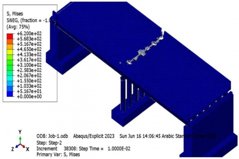
In this section, the results related to the analyzed bridge are presented. As previously mentioned, the bridge featured Columns 1 and 5 and was analyzed under two explosion scenarios: one above the bridge and one beneath the bridge. Below are the results (stress, compression damage, tensile damage) for the analysis of the bridge when the explosion occurs above it and with type 1 CFDST columns. The list of results and the distribution of stresses on the bridge in the a those facing the explosion, exceed the yield strength of 420 MPa and reach the ultimate strength at 620 MPa.
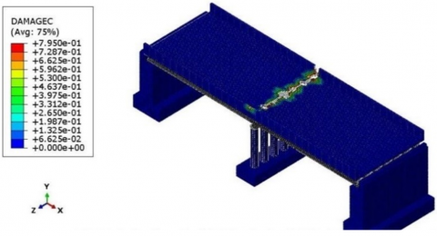
Figure 13. Stresses, compression damage and Tensile damage in the explosion Above the bridge in the sample CFDST columns type 1
Figure 14. Stresses, compression damage and Tensile damage) in the explosion Above the bridge in the sample CFDST columns type 5
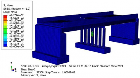
Figure 15. Stresses, compression damage and tensile damage in the explosion beneath the bridge in the sample CFDST columns type 1
Figure 16. Stresses, compression damage and Tensile damage in the explosion beneath the bridge in the sample CFDST columns type 5
The results obtained in this section indicate that in the scenario where the explosion occurs above the bridge, the upper part of the bridge resists the explosive pressure, and the columns play a much smaller role in this explosion scenario. Consequently, the damage values for tensile and compressive forces, as well as the stress distribution, are very similar for both Column 1 and Column 5 models. A noteworthy observation from the results is that the concrete section above the bridge is significantly weaker in tensile damage compared to compressive damage, highlighting substantial tensile damage to the concrete. But the Results for the Explosion Scenario Under the Bridge and in Front of the Columns for the two bridge models with Columns 1 and 5.
As observed in the Figures 13-16, the amount of damage and the red-colored areas in Model 5 are significantly less than in Model 1. This indicates that Column 5 has resisted the explosive load more effectively. Further results highlighting the improved performance of Column 5 in the bridge under the explosion are presented in the following sections.
In the Figure 17, stresses were monitored over time at a specific point chosen to represent the damaged area at a height of 3m on the side facing the explosion from the fourth middle column, which is located within a row of 7 columns in the bridge. In the figure, the orange line representing the stress of column 5 was below the blue line representing column 1. This means that the stresses of column 5 were less than 1 for the same condition and location on the two columns, which indicates that column 5 was the stronger and column 1 was weaker.
Figure 17. Stress-time distribution in the explosion under the bridge in models with column number 1 and 5
Figure 18. Damage dissipation energy distribution in models with column number 1 and 5
Figure 19. Displacement-time diagram in models with column number 1 and 5
Figure 20. The location of pick points on column type 5 and the pressure stresses (front surface, side surface, back surface)
Figure 21. Stresses pressure vs time in column type 5
The amount of energy dissipated due to damage in the type 1 column model is greater than in the type 5 column model, indicating that the type 1 column model is weaker while the type 5 is stronger (Figure 18), and the displacement in columns number 1 is greater than in columns number 5 as shown in Figure 19.
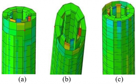
When we take specific points at the explosion level to monitor the compressive stress on the front, side, and back surfaces of the column, the results show that the stresses on the front at the beginning of explosion are more than ten times higher than side and back surfaces as shown in Figures 20 and 21.
The results from the analyses in this section indicate a significant improvement in the behavior of the bridge columns when using the proposed Column 5 from this study. This enhancement led to a reduction in stress, tensile and compressive damage, and displacement by 15% to 40%. In order to study the column section within the bridge model, we take three points on the column body after performing the deletion and cutting operations in the ABAQUS program shown in the previous chapter. One of the points is facing the explosion, the other is on the side, and the third is at the back surface.
The results show that the max. pressure stresses on the side opposite the explosion point are twenty times greater than on the side next to the column and in turn are greater than on the back side of the column. Note that the three points are on the same level. Also, the column type 1 appears the same pattern. It is necessary to evaluate the structural performance of CFDST columns and their ability to absorb the energy resulting from the explosion and their efficiency in resisting the high loads resulting from their exposure to explosion loads. A dynamic analysis has been integrated that takes into account the loads resulting from explosions such as the generated pressure, the duration of the load and the intensity of the explosion. It also requires updating the design standards to include explosion resistance standards with the determination of safety limits based on studies that simulate real conditions such as enhancing the thickness of steel pipes to withstand the pressures resulting from the explosion, as the thickness of the pipes was used in the research at 5 cm. The proportions of concrete and steel can be improved to provide additional rigidity and choose materials with a high energy absorption capacity. The concrete used can be improved through additives to increase its durability and thus its ability to resist explosions, as well as using high-strength steel and improving the bonds between concrete and steel within the column. Modern construction techniques can be relied upon to reduce the disparity in the distribution of materials between steel and concrete by using three-dimensional modeling to ensure the implementation of an explosion-resistant design accurately, as well as conducting tests to simulate explosions before field implementation to ensure the durability of the manufactured columns. Computational modeling can also be used in response analysis, thus identifying weaknesses. Potentially, it is also necessary to modify the design of future bridges in locations close to sources of risk such as industrial areas and roads with high traffic efficiency by using reinforced columns with the addition of additional layers of protection or metal linings as in the research models to obtain bridge designs capable of withstanding explosions with minimal damage to ensure the continuity of work even in emergency situations.
This study investigated the structural behavior of CFDST columns under explosive loading through simulations conducted using the Conwep feature in ABAQUS. Five CFDST columns with varying reinforcement configurations were modeled, subjected to pressure generated by explosions equivalent to 250 kg of TNT, with a fixed detonation distance. Furthermore, bridge simulations were carried out using the strongest and weakest column types to evaluate performance under blast conditions, from all these investigations, the following finding emerged:
1. Column 5 demonstrated significantly better performance in stress tensile, compressive damage, and distance compared to Column 1, especially in explosion scenarios below in the bridge, with improvements of 15%-40%.
2. Using Column 1 or Column 5 showed no significant impact on bridge performance during explosions above the bridge.
3. CFDST columns exhibited excellent blast resistance due to concrete energy dissipation properties, with reinforced columns outperforming unreinforced ones.
4. Tensile damage in concrete was higher than compressive damage, highlighting the need to strengthen concrete against tension.
5. Blast loads caused concrete crushing or denting of the outer pipe, with an optimal blast distance of 4.5 meters identified for 250 kg TNT explosion.
[1] Wang, H., Wu, C., Zhang, F., Fang, Q., et al. (2017). Experimental study of large-sized concrete filled steel tube columns under blast load. Construction and Building Materials, 134: 131-141. https://doi.org/10.1016/j.conbuildmat.2016.12.096
[2] Li, M., Xia, M., Zong, Z., Wu, G., Zhang, X. (2023). Residual axial capacity of concrete-filled double-skin steel tube columns under close-in blast loading. Journal of Constructional Steel Research, 201: https://doi.org/107697.10.1016/j.jcsr.2022.107697
[3] Ding, Y., Wang, M., Li, Z.X., Hao, H. (2013). Damage evaluation of the steel tubular column subjected to explosion and post-explosion fire condition. Engineering Structures, 55: 44-55. https://doi.org/10.1016/j.engstruct.2012.01.013
[4] Luccioni, B.M., Ambrosini, R.D., Danesi, R.F. (2004). Analysis of building collapse under blast loads. Engineering Structures, 26(1): 63-71. https://doi.org/10.1016/j.engstruct.2003.08.011
[5] Yan, B., Zhou, Y.H., Liu, F., Jiang, Z.G. (2015). Numerical study on damage mechanism of PRC T-beam under close-in blast loading. Applied Mechanics and Materials, 730: 55-64. https://doi.org/10.4028/www.scientific.net/AMM.730.55
[6] Jeyarajan, S., Liew, J.R., Koh, C.G. (2015). Vulnerability of simple braced steel building under extreme load. The IES Journal Part A: Civil & Structural Engineering, 8(4): 219-231. https://doi.org/10.1080/19373260.2015.1068385
[7] Liu, Y., Yan, J.B., Huang, F.L. (2018). Behavior of reinforced concrete beams and columns subjected to blast loading. Defence Technology, 14(5): 550-559. https://doi.org/10.1016/j.dt.2018.07.026
[8] Lacroix, D., Doudak, G. (2016). Behaviour of glued-laminated (glulam) beams and columns subjected to simulated blast loads. In World Conference on Timber Engineering, Vienna, Austria.
[9] Bedon, C., Amadio, C., Sinico, A. (2014). Numerical and analytical investigation on the dynamic buckling behavior of glass columns under blast. Engineering Structures, 79: 322-340. https://doi.org/10.1016/j.engstruct.2014.08.024
[10] Crawford, J.E. (2013). State of the art for enhancing the blast resistance of reinforced concrete columns with fiber-reinforced plastic. Canadian Journal of Civil Engineering, 40(11): 1023-1033. https://doi.org/10.1139/cjce-2012-0510
[11] Echevarria, A., Zaghi, A.E., Chiarito, V., Christenson, R., Woodson, S. (2016). Experimental comparison of the performance and residual capacity of CFFT and RC bridge columns subjected to blasts. Journal of Bridge Engineering, 21(1): 04015026. https://doi.org/10.1061/(ASCE)BE.1943-5592.0000762
[12] Li, J., Wu, C., Hao, H., Liu, Z. (2017). Post-blast capacity of ultra-high performance concrete columns. Engineering Structures, 134: 289-302. https://doi.org/10.1016/j.engstruct.2016.12.057
[13] Roller, C., Mayrhofer, C., Riedel, W., Thoma, K. (2013). Residual load capacity of exposed and hardened concrete columns under explosion loads. Engineering Structures, 55: 66-72. https://doi.org/10.1016/j.engstruct.2011.12.004
[14] Al-Thairy, H. (2018). Behaviour and failure of steel columns subjected to blast loads: Numerical study and analytical approach. Advances in Materials Science and Engineering, 2018(1): 1591384. https://doi.org/10.1155/2018/1591384
[15] Nassr, A.A., Razaqpur, A.G., Tait, M.J., Campidelli, M., Foo, S. (2014). Dynamic response of steel columns subjected to blast loading. Journal of Structural Engineering, 140(7): 04014036. https://doi.org/10.1061/(ASCE)ST.1943-541X.0000920
[16] Nawar, M.T., Arafa, I.T., Elhosseiny, O.M. (2022). Numerical damage evaluation of perforated steel columns subjected to blast loading. Defence Technology, 18(5): 735-746. https://doi.org/10.1016/j.dt.2021.03.019
[17] Li, M., Zong, Z., Liu, L., Lou, F. (2018). Experimental and numerical study on damage mechanism of CFDST bridge columns subjected to contact explosion. Engineering Structures, 159: 265-276. https://doi.org/10.1016/j.engstruct.2018.01.006
[18] Zhang, F., Wu, C., Wang, H., Zhou, Y. (2015). Numerical simulation of concrete filled steel tube columns against BLAST loads. Thin-Walled Structures, 92: 82-92. https://doi.org/10.1016/j.tws.2015.02.020
[19] Ahmed, M., Liang, Q.Q., Patel, V.I., Hadi, M.N. (2019). Local-global interaction buckling of square high strength concrete-filled double steel tubular slender beam-columns. Thin-Walled Structures, 143: 106244. https://doi.org/10.1016/J.TWS.2019.106244
[20] Hassanein, M.F., Elchalakani, M., Patel, V.I. (2017). Overall buckling behaviour of circular concrete-filled dual steel tubular columns with stainless steel external tubes. Thin-Walled Structures, 115: 336-348. https://doi.org/10.1016/j.tws.2017.01.035
[21] Elchalakani, M., Patel, V.I., Karrech, A., Hassanein, M.F., Fawzia, S., Yang, B. (2019). Finite element simulation of circular short CFDST columns under axial compression. Structures, 20: 607-619. https://doi.org/10.1016/j.istruc.2019.06.004
[22] Li, M., Zong, Z., Hao, H., Zhang, X., Lin, J., Liao, Y. (2020). Post-blast performance and residual capacity of CFDST columns subjected to contact explosions. Journal of Constructional Steel Research, 167: 105960. https://doi.org/10.1016/j.jcsr.2020.105960
[23] Yan, X.F., Zhao, Y.G. (2020). Compressive strength of axially loaded circular concrete-filled double-skin steel tubular short columns. Journal of Constructional Steel Research, 170: 106114. https://doi.org/10.1016/j.jcsr.2020.106114
[24] Albero, V., Ibañez, C., Piquer, A., Hernández-Figueirido, D. (2021). Behaviour of slender concrete-filled dual steel tubular columns subjected to eccentric loads. Journal of Constructional Steel Research, 176: 106365. https://doi.org/10.1016/j.jcsr.2020.106365
[25] Li, M., Zong, Z., Hao, H., Zhang, X., Lin, J., Xie, G. (2019). Experimental and numerical study on the behaviour of CFDST columns subjected to close-in blast loading. Engineering Structures, 185: 203-220. https://doi.org/10.1016/j.engstruct.2019.01.116
[26] Momeni, M., Hadianfard, M.A., Bedon, C., Baghlani, A. (2019). Numerical damage evaluation assessment of blast loaded steel columns with similar section properties. Structures, 20: 189-203. https://doi.org/10.1016/j.istruc.2019.04.002
[27] Xia, M., Li, M., Zong, Z., Lin, Y., Liu, Y. (2024). Experimental and numerical study on dynamic behavior of precast segmental CFDST columns under large equivalent explosions. Journal of Constructional Steel Research, 220: 108830. https://doi.org/10.1016/j.jcsr.2024.108830
[28] Li, M., Wang, L., Lin, Y., Zong, Z., Zhang, X. (2023). Experimental study on the residual seismic performance of CFDST columns after contact explosion. Thin-Walled Structures, 190: 110973. https://doi.org/10.1016/j.tws.2023.110973
[29] Mi, Y., Ren, H., Sun, C., Zhao, J., Wang, W., Yang, Z., Chen, Y. (2024). Dynamic behavior and residual performance of CFDSTCs under coupled collision and blast loads. Case Studies in Construction Materials, 22: e04147. https://doi.org/10.1016/j.cscm.2024.e04147
[30] Gangolu, J., Grisaro, H.Y. (2024). Axial load ratio effect on wide-flange columns subjected to far field detonations. Journal of Constructional Steel Research, 223: 109009. https://doi.org/10.1016/j.jcsr.2024.109009
[31] Yang, Z., Mi, Y., Wang, W., Zhao, J., Chen, Y. (2024). Numerical simulation of hollow-core FRP-concrete-steel column subjected to the combined collision and blast loads. Case Studies in Construction Materials, 22: e04143. https://doi.org/10.1016/j.cscm.2024.e04143
[32] Yimer, M.A., Dey, T. (2024). Dynamic behavior of full-scale GFRP bar-reinforced ultra-high-performance concrete-encased concrete-filled double-skin steel tubular bridge columns under lateral impact loading. Structures, 70: 107674. https://doi.org/10.1016/j.istruc.2024.107674
[33] Gao, B., Wu, J., Zhao, R., Feng, X., Wang, Z. (2023). Residual seismic resistance of CFDST columns after a close-in explosion: Experimental study. Structures, 48: 1082-1101. https://doi.org/10.1016/j.istruc.2023.01.030
[34] Khalaf, A.A., Naser, K.Z., Kamil, F. (2018). Predicting the ultimate strength of circular concrete filled steel tubular columns by using artificial neural networks. International Journal of Civil Engineering and Technology, 9(7): 1724-1736.