Satheeshkumar Palanisamy*![]() | Ahmed J. Obaid
| Ahmed J. Obaid![]() | Prabhu Thiyagarajan
| Prabhu Thiyagarajan![]() | Nivethitha Thangavelsamy
| Nivethitha Thangavelsamy![]() | Luís Miguel Cardoso
| Luís Miguel Cardoso![]() | Zdzislaw Polkowski
| Zdzislaw Polkowski![]()
© 2024 The authors. This article is published by IIETA and is licensed under the CC BY 4.0 license (http://creativecommons.org/licenses/by/4.0/).
OPEN ACCESS
This article presents a novel concept for a tiny stepped impedance resonator (SIR) to ease the application of bandpass filters. In recent years, its significance has expanded due to the growing availability of ground plane windows and a floating conductor in the substrate. We propose a small BPF that utilizes a folded SIR transmission line to achieve high performance at low size. The suggested BPF replaces the λg/4 transmission line present in traditional stub BPFs with a T-shaped SIR coupled to a J-inverter structure (transmission line). In addition to the short stubs included in regular stub BPFs, a folded SIR is included here. With this method, we are able to drastically cut the BPF's footprint. The benefits of a BPF are its compact size, negligible insertion loss, and high bandwidth. Because of the ground plane window, the characteristic impedance of the microstrip line is enhanced. This new value is then applied to the calculation that determines the inductive area of the quasi-lumped stepped impedance resonator. This resulted in a slightly smaller device than it would have been otherwise. In addition, a floating conducting microstrip patch is placed directly below the capacitive zone, pushing the filter's initial spurious band even higher. After this, the out-of-band rejection of the gadget sees a significant improvement. By strengthening the coupling between nearby resonators, achieving a wider spectrum of bandwidths within the range conceivable is also feasible. This article aims to compare several filter designs that incorporate newly developed resonator and regular resonators that are already in use. The proposed filter has the centre frequency response at 3.6GHz having insertion loss of 2.5dB and bandwidth increment of 115%, reduction in size dimension of 0.527×0.25mm2. The suggested BPF is flat, making it amenable to semiconductor fabrication at scale. The potential for this design's application in fields as diverse as defense, healthcare, and industry is high.
microstrip, transmission zero, stepped-impedance, spurious response, wireless communication
In the recent trends in communication, such as green communication and radar systems, removing RF noises becomes an essential quality to be taken into the care of for better performance [1]. The planar bandpass filters [2] are the major components in the current 5G wireless communication, which utilize spectrum bands such as 700 MHz, 3.57 GHz, and 25.8 GHz [3]. Various techniques such as couple line, hairpin, combine, step, and stub impedance [4] are reported in the literature.
Many have talked about making printed planar microwave filters smaller in the last few years. This is because low-frequency wireless and mobile communication systems are becoming increasingly common. Examples of this type of research can be found in references [5-7]. Because they work at low frequencies, conventional distributed resonators are too big to work well. As a result, larger structures have been phased out in favor of smaller ones. Hairpin resonators [8] were replaced for half the wavelength resonators, which were used to create parallel-coupled line resonating filters [9]. Open-loop square resonators [10] are a more compact alternative to the hairpin resonator, though this resonator still functions as a distributed device and produces excessively complex layouts at lower frequencies. The presence of unwanted spurious harmonics reduces the amount of out-of-band rejection, another disadvantage of distributed resonators. Compact quasi-lumped resonators can be used to overcome this issue, but the increased losses they incur are a trade-off. There is a lot more capacitance in which the hairpin resonator is folded [11] than in conventional hairpin or open-loop resonators, which makes it smaller. It is possible to obtain similar findings by employing the open-loop impedance resonators suggested in references [12, 13], now known as folded Stepped-Impedance Resonators (SIRs) [14]. It's possible to think of this resonator as a line with a low-impedance pair of lines linked with a high characteristic impedance. As an LC quasi-lumped resonator, the structure works at low resonance frequencies for capacitance values in the section of the wide coupled line that is relatively high. Inductance (L) comprises short sections of high-characteristic-impedance microstrip lines, and a short pair of electrically connected microstrip lines make up the rest and provides the capacitance (C). The resonator's quasi-lumped design automatically eliminates the problem of a first spurious transmission band. More advanced SIRs have been applied to filter design to achieve compactness and an expansive upper stopband.
Various methods have been proposed to downsize SIR BPFs, encompassing Meandering [15]: Increasing electrical length by folding resonators while maintaining physical size. Substrate selection: Utilizing high-permittivity substrates to reduce required physical length. Coupling element design [16]: Meticulous design of coupling structures (e.g., interdigital capacitors) to achieve desired filtering characteristics and miniaturization. For harmonic suppression, diverse approaches have been investigated. Trap resonators [17]: Introducing additional resonators tuned to trap and dissipate harmonic frequencies. Impedance transformation [18]: Tailoring impedance profiles to suppress harmonics while preserving the desired passband response. Coupling strategy [19]: Designing coupling elements to minimize coupling at harmonic frequencies. Performance metrics for SIR BPFs with harmonic suppression encompass [20]: Center frequency and bandwidth, Defining the desired passband. Insertion loss, Quantifying signal attenuation within the passband. Return loss, Indicating matching between the filter and source/load. Stopband rejection, Measuring attenuation of unwanted frequencies outside the passband, particularly at harmonics [21]. Size and complexity, desirably smaller size and lower complexity. Table 1 shows the literature, relevant to the proposed work. Framing the Novelty of Your Work: To effectively highlight the uniqueness of the proposed work, considered the following aspects: Miniaturization approach, Harmonic suppression mechanism, Performance improvement in such a way to achieve better insertion loss, return loss and stopband rejection. Improving coverage and optimization of bandwidth are the key highlights of 5G communication [22]. The popular variety of filtering structures used for 5G, has a very narrow bandwidth. Microstrip patch antenna is the most popular variety of antennas with certain limitations in using in real time applications. The patch antenna's narrow band characteristic limits its use in multiband and wide band applications. A wideband radiation is needed for 5G antenna as the communication channels in the fifth-generation communication requires high bandwidth generally [23]. Because most communication applications nowadays require multiband and large bandwidth, the patch antenna and its ground plane can be modified to accommodate the desired radiation properties.
The remaining part of this document is structured as follows: Section 3 outlines the suggested miniaturised band pass filter using folded SIR with the relevant mathematical formulas. Section 4 presents the simulated and experimental results of the proposed filter design. Lastly, Section 5 provides the conclusion.
Table 1. Examining the relevant conventional microstrip filters
|
Reference No. |
Adopted Filter Model |
Features |
Challenges |
|
[15] |
Four SRRs loaded in the superstrate |
•Good directivity •Broader bandwidth |
Reduced gain and interferences |
|
[16] |
Finite Element Method model |
•Efficiency is high. |
Impedance mismatching leads reduction in return loss. |
|
[17] |
Cantor set the Clover model |
•Return loss is reduced. |
Very complex |
|
[18] |
Modified inter-digital capacitor (MIDC) model |
•Return loss is reduced. •Gain is high |
More attention must be paid to antenna system miniaturization. |
|
[19] |
CSRR metamaterial cell -Particle Swarm Optimization-ANN model |
•Stable radiation pattern •Peak gain of 6.3 dB •Peak radiation efficiency of 98.3% |
Requires computation of different dimensions. |
|
[20] |
BF-PSO model |
•Utilization of time is low. •High bandwidth |
We need to focus on the cost function. |
|
[21] |
Hexagonal patch SRR inspired metamaterial substrate |
•Less array size •Minimal return loss |
Diverse switching techniques must be exploited for picking frequencies. |
|
[22] |
Genetic Algorithm |
•Computational complexity is reduced. •The accuracy is high. |
The flexibility is not fixed at all. |
|
[23] |
SRPA |
•The performance efficiency is enhanced. •High gain •The size is miniaturized. |
It is used only for short ranges. |
Short snippets of a quarter wavelength When the vertical size of the BPF needs to be decreased, it is common practice to employ a BPF rather than a quarter-wavelength open stub BPF [24]. However, in BPFs with λg/2 open stubs or λg/4 short stub (18.7 mm×18.9 mm at 5.8 GHz and 0.45 λg×0.19 λg), there is no design that can minimize the transmission line’s (TL) horizontal-size [25]. Currently, a dielectric ($\varepsilon_r$) substrate of high value is utilized to shrink the size of a BPF, but this method is prohibitively expensive. Therefore, there is a pressing need to develop BPFs with desirable characteristics such as high response, low cost and compact size [26].
Numerous studies have been conducted to minimize the footprint of stub BPFs while yet providing abundant bandwidth [27]. Zeroth-order resonance (ZOR) was employed by Palanisamy et al. [28] to create a BPF measuring 12.9 mm×5.9 mm with a bandwidth of 120%. However, coupling losses were produced since this BPF employed feeding line of coupling structure. The proposed BPF in reference [29] had an in/output coupling structure and used the defective ground structure (DGS) method to achieve a bandwidth of 116%. This BPF had a number of drawbacks, including its large size, the coupling losses it caused, and the parasitic characteristic it caused between the ground and transmission line. In reference [30], a BPF with a 109% bandwidth and a dimension of 23.4 mm 10 mm was presented. The DGS method was also utilized by this BPF. However, it had poor insertion losses and poor parasitic performance between the transmission line and ground. Broadband pass filters (BPFs) of large dimensions (123% [31] and 146%) were disclosed in the study [32]. These BPFs ranged in size from 32 mm 10 mm to 13.0 mm 10.0 mm to 150 mm 150 mm. High insertion losses (0.8 dB [33], 0.3 dB [34], and 0.55 dB [35]) were another drawback of these devices.
Using a folded SIR structure and T-shaped SIR transmission line, we present a small BPF with λg/4 short circuited stubs. Transmission lines in the shape of a T and folded SIR are planned to cut down on both the horizontal and vertical lengths. Folded and T-shaped SIRs replace the protruding series λg/4 transmission line and shunt λg/4 short stubs along the vertical and horizontal axes, respectively, to reduce the overall footprint of the proposed BPF. The small a BPF is easy to build and has negligible insertion losses.
The guided wavelength and the effective dielectric constant values are essential in designing slot in a dielectric substrate. Consider λcutoff is the cut off wavelength, the guided wavelength (λguided) of the slot is given by:
$\lambda_{\text {guided }}=1 / \sqrt{\left(\frac{1}{\lambda_0}\right)^2-\left(\frac{1}{\lambda_{\text {cutoff }}}\right)^2}$ (1)
The slot antenna's effective dielectric constant (εeff) is calculated as follows:
$\varepsilon_{\text {eff }}=\frac{\varepsilon_{\text {reff }}+1}{2}$ (2)
Consider the angular cut off frequency as ωc, angular resonant frequency as ω0, g1 is the prototype value of the Butterworth small pass filter type, Z0 is the characteristic impedance, c is the swiftness of light then the inductance (L) and capacitance (C) values shall be found by:
$L=\frac{1}{4 \pi^2 c f_0^2}$ (3)
$C=\frac{\omega_c}{Z_0 g_1} \cdot \frac{1}{\omega_0^2-\omega_c^2}$ (4)
The bandwidth (B) of the wideband patch antenna is the difference between the lower (fLower) and higher (fHigher) cutoff frequencies:
$B=f_{\text {Lower }}+f_{\text {Higher }}$ (5)
The central frequency (FCentral) along the antenna bandwidth is given by:
$F_{\text {Central }}=\left(f_{\text {Lower }}+f_{\text {Higher }}\right) / 2=\sqrt{f_{\text {Lower }} f_{\text {Higher }}}$ (6)
Fractional bandwidth (BW) is given by the ratio of the general bandwidth of the antenna to its central frequency:
BW=B/FCentral (7)
Fractional bandwidth (BW) shall be expressed in terms of percentage as:
% BW=(B/FCentral)×100% (8)
The different ground plane structures with several length sizes like full length L, three quarters length 3L/4, half-length L/2 and quarter length L/4 are shown in Figure 1. The ground plane is reduced to three fourth of its size and then to half for widening the bandwidth. The return loss plot of the variety of defected ground structures used in this antenna design.
Figure 1. Circuit scheme of tunable transmission zeroes by tapping the input and output resonators
Figure 2. With floating conductor and ground plane window representing folded stepped impedance resonator
Because of the lines that run parallel to each resonator, the general layout of each microstrip circuit is shown in Figure 1. Because of the adjustment, the value of this device's input and output impedances has increased by a factor of three due to the change. Both the input and output ports use step-impedance microstrip lines, which are placed close to the characteristic impedance Z0. Figure 2 illustrates the standard SIR structure. On each resonator's resonator, voltage distributions can be either asymmetric (referred to as odd mode) or symmetric (referred to as even mode). It is possible to estimate the resonance frequencies of the SIR, as stated in reference [29].
$\tan \theta_1=\operatorname{Rcot} \theta_2\left(\right.$ odd mode at $\left.f=f_1\right)$ (9)
$\cot \theta_1=-R \cot \theta_2\left(\right.$ odd mode at $\left.f=f_2\right)$ (10)
where, SIR impedance ratio, $R=\frac{Z_2}{Z_1}$.
The analysis of transmission lines within Step-Impedance Resonators (SIRs), particularly for odd mode resonance at frequency f1, heavily relies on the equation tanθ1=Rcotθ2 [36]. Let's delve into the significance of its components:
θ1 and θ2: These represent crucial parameters of the SIR structure, corresponding to phase shifts or electrical lengths along the transmission lines as understood in transmission line analysis.
R: This signifies the SIR's impedance ratio, defined as R=Z2/Z1, where Z1 and Z2 represent the impedances at distinct sections of the transmission line.
tanθ1 and cotθ2: These terms involve trigonometric functions applied to the respective angles. tanθ1 refers to the ratio of the opposite side to the adjacent side in a right triangle formed by θ1, while cotθ2 denotes the opposite ratio for θ2.
This equation establishes a critical relationship between the phase angles (θ1 and θ2) and the impedance ratio (R) within the SIR structure specifically for odd mode resonance at frequency f1. Understanding this relationship is paramount for both comprehending and designing transmission lines, particularly those incorporated into resonant structures. By leveraging this equation, engineers can optimize transmission line behavior and achieve desired resonant characteristics in SIRs, leading to advancements in various applications utilizing these structures.
When looking into SIRs, a crucial consideration is the value of impedance ratio, R. θA denotes the length of a specific type of SIR.
θA=2(θ1+θ2)=π/2 (11)
Using this tapped coupling and the values conducted by Guo et al. [30], we can add a new transmission zero. Zero's frequency may be figured out by assuming a quarter-wave is open. In order to reduce the input impedance at the tap location, inserted a stub to the left of the tap.
Adjusting the transmission zero frequency requires that the tap point on the I/O SIRs be able to be changed around with relative ease. However, the SIR Qsi values that the filter specification has locked in cannot be changed in any way. After selecting the tap point for a zero frequency calculated in advance, the Qsi value can be adjusted to keep the same Qsi value. If the required resistance value (RL) is lower than 50 ohms, then the impedance transformation can be carried out with the help of a quarter-wave transformer.
The process of designing a folded SIR structure involves meticulous consideration of multiple factors to achieve specific performance objectives. Let's delve into the reasoning behind opting for a folded SIR structure and discuss the significance of the T-shaped SIR concerning improvements in performance:
Design process-> Objective definition- Clearly articulate the design objectives, encompassing parameters.
Analysis of requirements: Scrutinize the application's requirements, taking into account aspects like bandwidth, impedance matching, and filtering.
Simulation and modeling: Modelling of SIR structures and evaluating their performance by examining resonance frequencies, impedance characteristics, and other pertinent parameters.
Trade-off analysis: Evaluate trade-offs among different SIR configurations, considering factors like size, complexity, and ease of fabrication.
Folded SIR choice: OPT for a folded SIR structure due to its capacity to achieve compact designs, enhance coupling, and improve overall performance. The folding technique facilitates more efficient integration within the allotted space.
Parameter tuning: Fine-tune the dimensions and parameters of the folded SIR to align with specific design requirements. This may involve adjusting the lengths and characteristic impedances of the transmission lines.
Validation: Validate the design through additional simulations and, if feasible, prototyping. Ensure that the chosen folded SIR structure meets the desired specifications.
i. Rationale for folded SIR structure
Compact design: The folding of the SIR structure enables a more compact design, particularly advantageous in applications where space is a critical constraint.
Enhanced coupling: The folding technique often enhances coupling between different sections of the SIR, resulting in improved performance regarding resonance and impedance matching.
Reduced size and inductance: The folded structure aids in reducing the overall size of the resonator and, consequently, the associated inductance. This proves advantageous in applications requiring a smaller footprint and enhanced integration.
ii. Significance of T-shaped SIR
Increased resonance control: The T-shaped configuration allows for superior control over resonance frequencies. Designers can fine-tune the resonator's performance by adjusting the dimensions of the T-shaped arms.
Improved impedance matching: The T-shaped SIR contributes to enhanced impedance matching, leading to improved signal transfer and reduced reflections.
Enhanced bandwidth: The T-shaped structure holds the potential to broaden the bandwidth of the resonator, providing more comprehensive frequency coverage for the intended application.
Versatility in applications: The T-shaped SIR design offers versatility, rendering it suitable for various applications where precise control over resonant frequencies and impedance characteristics is paramount.
The patterning of the substrate's back-side metallization has recently been used to improve the performance of several compact printed resonators [31]. Such ground structures are called DGS. The new resonator depicted in Figure 1 is based on that research line. An improved folding SIR with a floating conductor resonator, similar to the ones described by Lee et al. [32]. After partially removing the ground plane area beneath the resonator, a metalized rectangular microstrip patch remnants inside the ground window and placed below the section of the linked line. This can be accomplished by reducing the size of the single strip section due to the increased characteristic impedance so that the window provides better bandpass characteristics. To put it another way, this paper focuses on the floating conductor's ability to improve the filter's out-of-band rejection. Avoid intermodulation distortion. To begin, the required pass band's first resonance frequency is close to the first resonance frequency of the standard folded SIR, while the second resonance frequency is considerably increased. Because of this, the first band can be better rejected. This mechanism opens up a new coupling mechanism between neighbor resonators, allowing for larger bandwidths.
T-shaped Stepped-Impedance Resonators (SIRs): Each T-shaped SIR can be conceptualized as a transmission line characterized by characteristic impedance (Zc) and electrical length (θ). The impedance variations within the T-shape can be expressed using lumped inductances (L) and capacitances (C).
J-inverter: Represented as a shunt admittance (Yj) at the junction of the T-shaped SIRs, the specific value of Yj is contingent upon the geometry and dimensions of the J-inverter. Coupling: The interaction between T-shaped SIRs is modeled through mutual inductances (M) or coupling coefficients (k).
Higher-order modes: T-shaped SIRs can support higher-order modes at multiples of the fundamental frequency, potentially contributing to unwanted harmonics in the filter response.
Harmonic suppression analysis: Investigate how design parameters (impedance steps, J-inverter admittance, coupling) influence the excitation and attenuation of higher-order modes. Techniques like modal analysis or studying the frequency dependence of the characteristic equation and S-parameters may be employed.
Stopband rejection: Assess stopband rejection at harmonic frequencies, with a specific focus on achieving the desired suppression level and understanding its dependence on design choices.
Non-idealities: Incorporate considerations for non-idealities such as conductor losses, radiation, and substrate effects in the analysis for more precise predictions.
Optimization: Apply optimization techniques to identify design parameters that achieve the desired performance at both fundamental and harmonic frequencies.
The ground plane window provides these additional benefits. Thus, we can now design filters with increased bandwidths and improved rejection levels above the first passband that are smaller than those based on conventional folded SIR resonators. Folded SIR with a floating conductor is an improved version of the proposed resonators. There is a metallic floating rectangular patch below the coupled lines section within the ground window due to parting with part of the ground plane below the resonator. Because of the window, the single strip section has a higher characteristic impedance, which reduces its size [33]. A more critical consideration in this paper concerns the floating conductor's ability to enhance the Filters' undesired band rejection level depending on this floating conductor structure [34]. The prevention of intermodulation distortion necessitates attention to this issue. First, the desired pass band's initial resonance frequency is close to the first resonance frequency of the typical folded SIR. At the same time, the 2nd resonating frequency band is meaningfully raised. Because of this, the first band can be better rejected. By opening a novel coupling mechanism, which improves the cohesion between nearby resonators [27], the ground plane window provides additional advantages, such as increased bandwidth. Thus, we can now design filters with increased bandwidths and improved rejection levels above the Ist pass band that are smaller than those based on conventional folded band pass SIR resonators.
5.1 Single resonator characterization
In this study, the model for the folded SIR with a floating conductor is simply an approximation because the coupled section has three conductors plus ground. There are now three quasi-TEM modes rather than the previously stated two. According to this theory, however, this is a practical application [28, 31]. A single transmission line section that contributes inductively has a characteristic impedance and εeff, an effective dielectric constant. Ze and Zo, as well as the effective modal impedances of the even (e) and odd (o) mode and effective permittivity $\varepsilon_{\text {eff }}^e \varepsilon_{\text {eff }}^0$, are the electrical parameters of the capacitive part of the resonator. This is the identical folded hairpin resonator circuit proposed by Lee et al. [32]. Afterward, two distinct resonance situations can be found:
$\tan \frac{\theta_s}{2} \tan \theta_0=R z_o$ (odd resonances)
$\tan \theta_e=-R z_e \tan \frac{\theta_s}{2}$ (even resonances) (12)
To calculate Rzo= $\frac{Z_O}{Z_S}$, Rze= $\frac{Z_e}{Z_s}$, where $\theta_s$ is the single line section's electrical length, θethe coupling line section's even (odd) mode's electrical length. The first odd mode resonance, f0, occurs at this frequency. Using these resonators as a basis, we can determine the frequency range of any filter that employs them. It is f1 relates to the first even mode resonance, the first spurious resonance.
5.2 Bandpass filter design
Take, for example, the following specifications for filter A: There are three orders of magnitude (N), a single-core frequency (f0=4 GHz), ripple (0.1 decibels), and a fractional bandwidth of 4%. The same substrate was used as in the previous part. Each filter was contained within a copper box with dimensions of 40×20 mm2. Thickness of 2.0mm was chosen for the air layers beneath and over the substrates, respectively. However, it is critical to emphasize that the metallic enclosure has a negligible effect on the first spurious band and pass band due to the severely limited electromagnetic environment surrounding metallic strips and slots. The printed metallization controls the filter's response at particular frequencies, but the enclosure has little effect on the filter's response. Bear in mind that this is not always true in the case of other deferred substrate structures [33, 34], where boundary dimensions are essential to design. This is a practical novelty and uniqueness of our design, as it enables the filter to be integrated as a component of a more intricate system without requiring changes to the system's physical structure.
It will be shown later that purposefully made compact housing can reduce microstrip line levels between the intended and spurious bands. You should keep the housing size manageable if you don't want spurious resonances above and near the pass band and lower the rejection level. When it comes to radiation, it is only relevant in the spurious band frequency zone. In the trials, the folded SIRs were folded to have the following parameters with dimensions: L2=4.1 millimeters. w0=0.46 millimeters, l1=5.27 millimeters, values of l3 that resonates at f0 for each resonating filter are as follows: l3=5.8 mm (conventional folded Stepped Impedance Resonator) and l4=3.8 mm (convolutional folded Stepped Impedance Resonator) (folded Stepped Impedance Resonator with floating conductor). When using a floating conductor, S=0.25 mm, wf=2.7 mm, and l=6.85 mm is all valid values.
As a point of comparison, we've included a design in which the width of the strip is also 0.25 mm, and the length of the microstrip is the same. The required to suit the resonance frequency is 64.4 mm. Following the typical design process based on estimating the coupling coefficient between nearby resonators, we have implemented our system. The coupling factor represents that distance between the resonators is the relaying function, denoted by the letter d. Unless the separations are minimal, it is possible to see an intriguing extra feature of the resonator presented in this paper: Traditional SIR folded in half, or open-loop impedance resonator has a lower coupling factor. Thus, the proposed geometry is less sensitive to dimensional constraints for a given bandwidth, allowing for greater bandwidths in the opposite direction. The specifications of filter A result in a coupling factor of K=0.037 due to the design. This necessitates the use of traditional folded SIRs that are incredibly close together. There are floating rectangular patches in the space between the resonators. On the other hand, fabricating is rather large and reasonably simple. For the in-out resonators, the external quality factor is used. Figure 3 illustrates the simulated broadband insertion losses of filters A, B, and C constructed using the resonators above.
Figure 3. S parameter of the traditional SIR filter
Consider designing a filter around the suggested resonator with greater relative bandwidth than the original resonator. The following specifications characterize filter B: central frequency f0=4.2GHz, order N=4, ripple=0.10 decibels, and fractional bandwidth=7%. Because the substrate is similar to the prior designs, no changes are necessary. The resonator geometry parameters are as follows: l2=2.08 mm, l1=3.62 mm, l3=4.01 mm, if=3.03 mm, l3=4.35 mm, wf=2.4 mm and s=0.35 mm. The filter specs include the coupling factors K12=0.045 and K23=0.039, respectively.
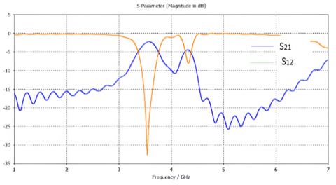
As a consequence of these values, the gap sizes are determined to be d12=0.3 mm and d23=0.34 mm, respectively. We can create the same filter using the traditional folded SIR with a gap between the resonators less than 30 micrometers wide. Consequently, even with more exact methods of fabrication, tolerances in dimensions would continue to play an increasingly significant role. A decent figure for the in-out resonators is Q=21.3, the external quality factor. The distance that must be maintained between the input and output resonators, which is equal to 3.71 millimeters, serves as the criterion for determining where the 45-degree feed lines, each of which has a width of 0.35 millimeters, must be positioned over the sides of both the input and output resonators to arrive at this value. Figure 4 presents a representation of the passband response provided by the filter. At a frequency of about 5.3 GHz, the insertion loss curve hits its highest point of 30 dB of maximum loss.
Figure 4. S parameter of the folder SIR filter
Figure 5. S parameter of the full wave simulated folded SIR BPF filter
Box size can be arbitrarily adjusted to achieve high rejection levels above and beyond the frequency range of a first-pass band. It has been possible to do a full-wave simulation of filter B using HFSS for two different box sizes. For comparison, an ensemble simulation for an endlessly broad box is presented. It should be noted that, for a box width of 19 mm, the Ensemble and HFSS values are highly similar to one another deficient transmission level is possible between the spurious passbands and the desired band when using a box width of 9 mm. The enclosure supports quasi-TE10 mode and is placed distant from the enclosure's cutoff point, in this case, of 9 mm width. In this mode, transmission is impossible because of the extraordinarily high reactive attenuation of the fields involved. In addition, about 80 dB of attenuation is achieved. The output port's evanescent electromagnetic field is strong enough to limit attenuation to 40-50 dB, even for a 21 mm wide box. Figure 5 shows insertion loss response of the full wave folded SIR Filter. A small effect of the lateral walls on the pass bands may be seen, but the enclosure's waveguide mode features strongly influence the rejection level between pass bands. Final thoughts on the transmission zeros identified in measurements and simulations but not considered by the filter's equivalent circuit. As a result of destructive interference between the microstrip system and other weak transmission strategies mechanisms, such as transient fields in the box or surface waves, these zeros are generated. The circuit model does not represent either of these methods at this time. Only at frequencies in the circuit model predicts minimum transmission levels, which is not very frequent, is this interference meaningful.
The proposed BPF is compared with others in Table 2, where parameters such as bandwidth, insertion loss, and overall device size are evaluated.
Table 2. Comparative analysis of S-parameters, size, bandwidth with proposed filter
|
Ref. |
Center Frequency [GHz] |
IL [dB] |
RL [dB] |
BW [%] |
Size [λg] |
Dielectric Constant |
|
[12] |
6.85 |
1.50 |
15.0 |
109 |
1.10×0.40 |
3.55 |
|
[13] |
6.75 |
0.80 |
11.0 |
100 |
0.60×0.54 |
3.55 |
|
[14] |
7.20 |
1.45 |
17.0 |
111 |
0.69×0.18 |
2.20 |
|
[15] |
6.95 |
0.42 |
19.0 |
97 |
0.128×0.37 |
3.55 |
|
Folded SIR BPF filter |
3.6 |
2.5 |
32 |
115 |
0.527×0.25 |
2.2 |
The filter's performance could be influenced by fluctuations in the fabrication process, including variations in substrate material properties and dimensions. These factors may compromise the consistency and reliability of harmonic suppression. Additionally, the process of miniaturization may result in higher insertion loss, potentially impacting the overall quality of the signal. Balancing size reduction and signal integrity becomes a critical limitation, particularly in applications where minimal signal degradation is imperative. The pursuit of optimal harmonic suppression may necessitate a intricate tuning procedure, posing challenges for users without extensive expertise in the implementation and adjustment of the filter.
We have demonstrated that the conventional folded Stepped Impedance Resonator used in manufacturing passband SIR filters can also be utilized in constructing the ground plane window for floating conductor-based passband filters. A transmission line resonator circuit model was utilized in an exhaustive study of the novel resonator, which was successfully concluded. We have shown that it is possible to simultaneously regulate the fundamental resonance of the SIR (f0) and the first spurious resonance using the floating conductor and the ground plane aperture. This permits us to enhance the level of rejection in the higher rejection band compared to bandpass filters based on standard folded SIRs, which limits our ability to do so. It has also been shown that it is feasible to lessen the size of resonators while concurrently raising the level of coupling between them. To illustrate the range of applications for the newly developed resonant structure, many filter architectures have been incorporated. The utilization of an enclosure with an appropriately constructed resulted in an exceptionally high level of rejection in the out-of-band region.
[1] Nedil, M., Denidni, T.A., Djaiz, A., Boutayeb, H. (2008). Ultra-wideband bandpass filters using multilayer slot coupled transitions. Journal of Electromagnetic Waves and Applications, 22(4): 501-516. https://doi.org/10.1163/156939308784150353
[2] Bai, L., Zhuang, Y., Zeng, Z. (2021). Compact quintuple notched-band UWB BPF with high selectivity and wide bandwidth. International Journal of Microwave and Wireless Technologies, 13(5): 435-441. https://doi.org/10.1017/S1759078720001348
[3] Shome, P.P., Khan, T. (2020). A quintuple mode resonator based bandpass filter for ultra-wideband applications. Microsystem Technologies, 26(7): 2295-2304. https://doi.org/10.1007/s00542-019-04697-5
[4] Zheng, X., Pan, Y., Jiang, T. (2018). UWB bandpass filter with dual notched bands using T-shaped resonator and L-shaped defected microstrip structure. Micromachines, 9(6): 280. https://doi.org/10.3390/mi9060280
[5] Gao, X., Feng, W., Che, W. (2017). Compact ultra-wideband bandpass filter with improved upper stopband using open/shorted stubs. IEEE Microwave and Wireless Components Letters, 27(2): 123-125. https://doi.org/10.1109/LMWC.2016.2647385
[6] Malherbe, J.A. (2018). Wideband bandpass filter with extremely wide upper stopband. IEEE Transactions on Microwave Theory and Techniques, 66(6): 2822-2827. https://doi.org/10.1109/TMTT.2018.2825342
[7] Yoon, K., Kim, K.G., Lee, T.H. (2022). Miniaturized bandpass filter using a combination of T-shaped folded SIR short loaded stubs. Sensors, 22(7): 2708 https://doi.org/10.3390/s22072708
[8] Zhang, X.C., Chen, X., Sun, L., Huang, Y.S., Gao, X.F. (2019). A microstrip stepped-impedance resonator bandpass filter based on inductive coupling. Frequenz, 73(1-2): 7-11. https://doi.org/10.1515/freq-2018-0112
[9] Yoon, K., Kim, K. (2021). Compact size of an interdigital band-pass filter with flexible bandwidth and low insertion-loss using a folded spiral and stepped impedance resonant structure. Electronics, 10(16): 2003. https://doi.org/10.3390/electronics10162003
[10] Li, C., Ma, Z.H., Chen, J.X., Wang, M.N., Huang, J.M. (2023). Design of a compact ultra-wideband microstrip bandpass filter. Electronics, 12(7): 1728. https://doi.org/10.3390/electronics12071728
[11] Zhang, M., Lei, P., Zhang, C., et al. (2023). An ultra-wideband integrated filtering antenna with improved band-edge selectivity using multimode resonator. Electronics, 12(15): 3264. https://doi.org/10.3390/electronics12153264
[12] Zhang, X.C., Xu, J., Yu, Z.Y. (2008). Design of quasi-elliptic bandpass filter based on slow-wave open-loop resonators. Journal of Electromagnetic Waves and Applications, 22(13): 1849-1856. https://doi.org/10.1163/156939308786375091
[13] Velazquez-Ahumada, M., Martel-Villagran, J., Medina, F., Mesa, F. (2010). Design of band-pass filters using stepped impedance resonators with floating conductors. Progress Electromagnetics Research, 105: 31-48. https://doi.org/10.2528/PIER10042010
[14] AlHawari, A.R.H., Ismail, A., Rasid, M.F.A., Abdullah, R.S.A.R., Esfeh, B.K., Adam, H. (2009). Compact microstrip bandpass filter with sharp passband skirts using square spiral resonators and embedded-resonators. Journal of Electromagnetic Waves and Applications, 23(5-6): 675-683. https://doi.org/10.1163/156939309788019895
[15] Wang, I.C., Lee, C.H., Hsu, C.I.G. (2009). Design of band-notched UWB BPF with very wide upper stopband using combined λ/4 TSSIR. Journal of Electromagnetic Waves and Applications, 23(2-3): 183-194. https://doi.org/10.1163/156939309787604463
[16] Martel Villagrán, J., Medina Mena, F. (2001). A suitable integral equation for the quasi-TEM analysis of hybrid strip/slot-like structures. IEEE Transactions on Microwave Theory and Techniques, 49(1): 224-227. https://doi.org/10.1109/22.900016
[17] Killamsetty, V.K., Mukherjee, B. (2017). Compact wideband bandpass filter for TETRA band applications. IEEE Microwave and Wireless Components Letters, 27(7): 630-632. https://doi.org/10.1109/LMWC.2017.2711515
[18] Xiao, F., Norgren, M., He, S. (2011). Compact third-order microstrip bandpass filter using hybrid resonators. Progress in Electromagnetics Research C, 19: 93-106. https://doi.org/10.2528/PIERC10092706
[19] Vegesna, S., Saed, M. (2012). Compact two-layer microstrip bandpass filters using broadside-coupled resonators. Progress in Electromagnetics Research B, 37: 81-102. https://doi.org/10.2528/PIERB11101708
[20] Palanisamy, S., Thangaraju, B. (2022). Design and analysis of clover leaf-shaped fractal antenna integrated with stepped impedance resonator for wireless applications. International Journal of Communication Systems, 35(11): e5184. https://doi.org/10.1002/dac.5184
[21] Kim, H.J., Choi, J.W., Seo, C.H. (2010). The open loop multiple split ring resonator based voltage controlled oscillator in 0.13 um CMOS. The Journal of Korean Institute of Electromagnetic Engineering and Science, 21(2): 202-207. https://doi.org/10.5515/kjkiees.2010.21.2.202
[22] Ho, M.H., Hsu, C.I.G., Hung, J.T., Shen, Y.L. (2022). Miniaturized trisection BPF design using size-reduced substrate integrated coaxial resonators. International Journal of Applied Electromagnetics and Mechanics, 68(2): 263-273. https://doi.org/10.3233/JAE-210114
[23] Nivethitha, T., Palanisamy, S.K., Prakash, K.M., Jeevitha, K. (2021). Comparative study of ANN and fuzzy classifier for forecasting electrical activity of heart to diagnose COVID-19. Materials Today: Proceedings, 45: 2293-2305. https://doi.org/10.1016/j.matpr.2020.10.400
[24] Satheesh Kumar, P., Jeevitha, Manikandan. (2021). Diagnosing COVID-19 virus in the cardiovascular system using ANN. In Artificial Intelligence for COVID-19, pp. 63-75. https://doi.org/10.1007/978-3-030-69744-0_5
[25] Palanisamy, S., Thangaraju, B., Khalaf, O.I., Alotaibi, Y., Alghamdi, S., Alassery, F. (2021). A novel approach of design and analysis of a hexagonal fractal antenna array (HFAA) for next-generation wireless communication. Energies, 14(19): 6204. https://doi.org/10.3390/en14196204
[26] Wu, Y., Liu, Y.A. (2011). A coupled-line band-stop filter with three-section transmission-line stubs and wide upper pass-band performance. Progress in Electromagnetics Research, 119: 407-421. https://doi.org/10.2528/PIER11072003
[27] Wang, J.P., Wang, B.Z., Wang, Y.X., Guo, Y.X. (2008). Dual-band microstrip stepped-impedance bandpass filter with defected ground structure. Journal of Electromagnetic Waves and Applications, 22(4): 463-470. https://doi.org/10.1163/156939308784150335
[28] Palanisamy, S., Thangaraju, B., Khalaf, O.I., Alotaibi, Y., Alghamdi, S. (2021). Design and synthesis of multi-mode bandpass filter for wireless applications. Electronics, 10(22): 2853. https://doi.org/10.3390/electronics10222853
[29] Sheta, A.F. (2008). A novel compact degenerate dual-mode square patch filter using cross H-shaped defected ground structure. Journal of Electromagnetic Waves and Applications, 22(14-15): 1913-1923. https://doi.org/10.1163/156939308787537928
[30] Guo, Y.C., Weng, L.H., Shi, X.W. (2009). An improved microstrip open-loop resonator bandpass filter with DGSS for WLAN application. Journal of Electromagnetic Waves and Applications, 23(4): 463-472. https://doi.org/10.1163/156939309787612301
[31] Kumar, S., Chandavarkar, B.R. (2021). DDOS prevention in IoT. In 2021 12th International Conference on Computing Communication and Networking Technologies, Kharagpur, India, pp. 1-6. https://doi.org/10.1109/ICAECA52838.2021.9675686
[32] Lee, T.H., Yoon, K.C., Kim, K.G. (2022). Miniaturized dual-band bandpass filter using T-shaped line based on stepped impedance resonator with meander line and folded structure. Electronics, 11(2): 219. https://doi.org/10.3390/electronics11020219
[33] Rao, Z.M., Wong, T.J., Ho, M.H. (2005). Forked stepped impedance resonator bandpass filter with harmonic suppression. In 2005 Asia-Pacific Microwave Conference Proceedings, Suzhou, China, p. 4. https://doi.org/10.1109/APMC.2005.1606275
[34] Tsai, L.C. (2011). Design of bandpass filters using miniaturized stepped-impedance resonators. In Proceedings of 2011 Cross Strait Quad-Regional Radio Science and Wireless Technology Conference, Harbin, China, pp. 567-570. https://doi.org/10.1109/CSQRWC.2011.6037013
[35] Tyurnev, V.V. (2010). Coupling coefficients of resonators in microwave filter theory. Progress in Electromagnetics Research B, 21: 47-67. http://doi.org/10.2528/PIERB10012103
[36] Abu-Abed, A., Lindquist, R. (2008). Capacitive interdigital sensor with inhomogeneous nematic liquid crystal film. Progress in Electromagnetics Research B, 7: 75-87. https://doi.org/10.2528/PIERB08022901
[37] Denis, S., Person, C., Toutain, S., Vigneron, S., Theron, B. (1998). Improvement of global performances of band-pass filters using non-conventional stepped impedance resonators. In 1998 28th European Microwave Conference, Amsterdam, Netherlands, pp. 323-328. https://doi.org/10.1109/EUMA.1998.338172