Anton Nugroho![]() | Wawan Aries Widodo*
| Wawan Aries Widodo*![]() | Is Bunyamin Suryo
| Is Bunyamin Suryo![]()
© 2024 The authors. This article is published by IIETA and is licensed under the CC BY 4.0 license (http://creativecommons.org/licenses/by/4.0/).
OPEN ACCESS
The development and refinement of air ventilation systems aboard ships are paramount for ensuring safety and operational efficiency. This comprehensive review systematically evaluates the existing literature on shipboard air ventilation and associated fire incidents, employing both bibliometric analysis and mathematical modeling methodologies. It has been observed that ventilation systems are predominantly classified into three categories: mechanical ventilation, natural ventilation, and hybrid systems combining mechanical ventilation with air conditioning (AC). These systems are imperative for regulating temperature, particularly in critical areas such as engine rooms, and for mitigating risks related to leaks and fires. International Maritime Organization (IMO) standards are consistently adhered to, reinforcing the effectiveness of these systems in controlling onboard environments. Furthermore, the application of mathematical models offers significant insights, facilitating the calculation and prediction of outcomes pertinent to ventilation-related research. These models prove crucial for addressing prevalent issues such as leaks and fire hazards within the maritime industry. Conversely, a bibliometric analysis highlights emerging research trends, identifying "ventilation," "ship," "Computational Fluid Dynamics (CFD)," "ship engine," "leakage," and "fire onboard" as focal keywords. This analysis not only underscores the current research focus but also guides future investigations, encouraging ongoing advancement and innovation in maritime research. This review thus serves as a vital resource for researchers aiming to explore and expand upon the thematic areas identified, potentially leading to breakthroughs in the design and implementation of ship ventilation systems.
ventilation, ship fire, ship safety, performance analysis, bibliometric analysis, mathematical modelling
Each ship has its own set of terms and conditions governing the utilization of air ventilation systems. The ventilation of the air is tailored to the specific requirements of each compartment. Consequently, some vessels solely rely on natural ventilation, while others necessitate mechanical ventilation systems or fans. The fans are utilized for air intake or exhaust, depending on the compartment's AC requirements. As per regulations, compartments storing flammable or hazardous liquids or gases must be mechanically ventilated to dissipate heat. The air exchange process is conducted per the room's cooling requirements to mitigate the fire risk [1]. An air handling unit (AHU) is a commonly employed ventilation system that offers ease of maintenance and operates at a low noise level.
The equipment compartment that has been installed requires air to operate effectively. This air is provided through mechanical air vents or supply air vents. The purpose of this air supply is essential for powering the cooling equipment. Natural ventilation is sufficient for areas that do not necessitate specialized equipment. Air vents are installed in passenger or engine rooms to enhance passengers and crew members' comfort. It is recommended that the amount of fresh air flow be at least 40% of the total number of individuals in the room [2]. Conversely, the air is either directly expelled or not circulated in areas such as toilet rooms, kitchen rooms, dining rooms, and washing rooms.
Research on ship fires is a prevalent topic within the shipping industry. The most common cause of these fires is reported to be unintentional accidents involving flammable fuels [3]. Specifically, fuel leaks from reserve fuel tanks are a frequent ignition source. Due to the high flammability and weight of the fuel, it is highly susceptible to burning [4]. While a ship engine fire may not immediately impact the vessel's movement, it can eventually restrict mobility. The primary concern, however, is the potential for harm to the crew, including injuries and fatalities [5]. Most fire incidents, approximately 56%, occur in the main engine room or auxiliary engines. The progression of a ship fire can be categorized into five stages: initial flame at the leak site, fire spreading, intense combustion, decay, and finally, extinguishment [6].
The shipping or maritime sector is confronted with considerable challenges, among which fires represent a significant source of loss, as evidenced by statistical analyses [7]. These fires typically occur in ship engine rooms, where various types of propulsion engines and flammable fuel are present [8]. Consequently, when a fire breaks out in the engine room, the resulting losses and impacts on the ship are substantial [9]. As a last resort, engine room insulation is frequently utilized to combat ship fires. This approach aims to create a sealed environment where the fire is contained within a closed room. As a result, a closed fire experiences higher pressure compared to an open fire [10]. Moreover, oxygen concentration gradually decreases as the combustion process unfolds. Previous studies have highlighted that fire behavior in enclosed ship spaces differs significantly from smoke or fire in open spaces, particularly in rooms equipped with ventilation systems [11-14].
Simplifying concerns regarding fires in ship engines can be achieved by isolating the fire location in the center of the engine room. Previous studies have extensively investigated the smoke or fire formation process in locked or sealed rooms [15-18]. Some studies have also reported on and described unsealed machine rooms [19-22]. In the event of a closed fire, plumes of fire rise upward. This vertical smoke-rising process continues as the hot smoke, denser than the surrounding air, enters the surrounding air. Once the smoke reaches the ceiling, it spreads horizontally to other room parts [20]. Consequently, the model of fire smoke filling the ship's engine room can be depicted as an enhanced filling box model [23].
Researchers have recently examined multiple reviews concerning ventilation fire safety on ships. In 2017, the ship's ventilation system was scrutinized alongside structural hydrodynamics and the implications of scaling on ventilation design [24]. A review in 2021 delved into the key aspects of regulations and standards governing shipboard air ventilation systems, particularly in light of the pandemic [25]. In 2022, a systematic review was conducted on methods and solutions for evacuating ship passengers during emergencies or accidents [26]. From 2023 onward, virtual reality (VR) was evaluated in firefighting processes and evacuation procedures during ship accidents [27]. This review aims to assess the regulations and air ventilation systems on ships and analyze air ventilation using a bibliometric approach with the assistance of VOSviewer to allow readers to explore the innovative aspects of air ventilation and fire research on ships.
The main motivation of this research review is to examine and explore the air ventilation system implemented on ships in order to mitigate the risks associated with leakage and fire incidents. The impact of air ventilation on the potential dangers of fire and leakage aboard a ship is significant. Hence, conducting this review holds utmost importance. The most significant aspect of this review is to scrutinize mathematical modeling in calculating each parameter, performance-related variables, energy analysis, and exergy analysis in the study of air ventilation and fire on ships. Bibliometric findings help researchers identify research gaps, novelty, and current trends. Conversely, a mathematical model review offers a comprehensive examination of variables and parameters pertinent to advancing research in a manner akin to previous studies. Consequently, integrating bibliometrics and mathematical modeling proves invaluable for researchers involved in the future design, construction, and enhancement of air ventilation systems and leak prevention mechanisms on maritime vessels.
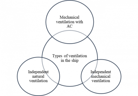
Figure 1 depicts a schematic concept illustrating the air ventilation system implemented on a ship. The ship's air ventilation system comprises three distinct components: natural air ventilation, mechanical air ventilation, and a combination of AC and mechanical ventilation. The independent natural ventilation component is a technical compartment that utilizes natural ventilation without any specialized equipment or operational models on the ship. Air inlet grilles are positioned in the lower section of the compartment to enhance natural circulation, while exhaust air grilles are located in the upper section. It is important to note that the minimum height of the ventilation openings above the ship's deck ranges from 70 cm to 90 cm.
The ship's mechanical air ventilation system, known as the mechanical ventilation system, consists of an intake air fan supply and an exhaust air fan system. It is essential to consider various compartments within the mechanical ventilation system, including the air supply to the room, the air cooling process, and removing flammable gases from the ship's room or engine room [28]. Typically, mechanical ventilation systems on ships are equipped with local cooling mechanisms, which involve fans that operate regularly within the room [29]. These ship room systems generally comprise components such as a fan that supplies air to the room, an exhaust air fan, and both supply and exhaust outlets [30].
The ship's engine room ventilation model is designed to provide air ventilation in the ship's engine room. It is characterized by having openings on the deck without any cover, allowing for stable airflow. According to the IMO standards [31], the air ventilation openings in engine rooms should have a 4.4-meter minimum height at the top and a 2.3-meter minimum height at the second position.
A commonly used AC system is employed to regulate the temperature in the engine room. This system utilizes an AHU for air circulation, with the air being returned to the room for heating or cooling purposes. Typically, this mechanical ventilation system with AC is installed in living rooms, meeting rooms, and similar spaces. Its purpose is to ensure the compartment's cooling or warming process is achieved as required. In order to enhance the efficiency of the ventilation system, some of the energy from the exhaust air can be recovered. However, the profitability of this energy recovery process is relatively low, as stated by Zender-Swiercz [32]. In smaller and medium-sized boats, ventilation units are equipped with small fans. These units may rely on natural air ventilation or a combination of air ventilation, fans, AC, and other types of fans to provide adequate ventilation.
Figure 1. A schematic concept of ventilation on a ship
3.1 General requirements for air ventilation
Ships' ventilation systems typically comprise various components [28], such as a ventilation system in the room and engine room of the vessel. Additionally, ventilation is required in areas like the kitchen, sleeping room, service room, weather dampers, fire dampers, ventilation ducts, supporting equipment, cargo spaces, and the surrounding environment. In engine rooms falling under category A and special passenger rooms, the kitchen room must be separated from the ventilation system according to the regulations set by the classification society and following IMO rules [33]. The galley air ventilation system is not mandatory for small ships with a maximum passenger capacity of 36 individuals and cargo ships below a 4000 gross tonnage threshold. Ensuring that the ventilation duct penetration section remains water- and fire-tight is crucial for the safety and prevention of hazards. Thin penetration channels pose risks regarding temperature and fire; therefore, their thickness and length must adhere to IMO standards [33] to guarantee safety.
The positioning of ventilation systems below ground level and their ability to prevent flooding risks comply with the terms and conditions outlined in references [34-36]. The regulations for integrated ventilation requirements on ships measuring 80 m and above are based on the guidelines set by the Association of International Classification Societies (UR) S27 [37]. As per these regulations, the ventilation system on the ship is located at the front of the deck. An explosion-proof shield is installed in the appropriate position for the ventilation system to mitigate the risk of explosions within the ship's vicinity. This shield is equipped with a square mesh protective screen measuring 13 mm to prevent any objects from entering the fan [38].
3.2 Main requirements and compartments
When the air vent is installed, the ship's engine can reach a maximum temperature of 45oC. The air ventilation system in the engine room consists of an air supply fan and an air exhaust fan, both of which have a high airflow rate [39]. This ventilation system ensures that the engine room's air conditions remain stable per established standards [40]. In cases where ships are not certified or do not adhere to temperature standards in the engine room, higher temperatures can be tolerated [41]. According to the International Organization for Standardization (ISO) 8861 standard, the air ventilation in the engine room must meet the required air flow rate. To achieve proper air ventilation in the engine room, it is necessary to conduct initial research activities such as simulations or CFD approaches [42].
The ventilation system's separation is necessary for the fuel room and engine tank. The engine room requires a minimum air speed of 30 changes per hour, achieved by implementing an extraction-type ventilation system [43]. Additionally, the ship's engine control room is equipped with an air ventilation and conditioning system to maintain a temperature below 27℃. This ventilation system extracts hot air from the room and replaces it with fresh air from the outside [44]. The air change process is conducted every hour in the flammable and dangerous liquid storage compartment.
The oxygen-acetylene and carbon dioxide (CO2) storage rooms maintain the ventilation system by implementing hourly air changes. On the other hand, the refrigeration machine room and battery room have fresh air changed either every hour or at intervals shorter than an hour. Installing a fan within less than 3 meters of the air exhaust duct is considered safe, adhering to the specified fan model [45]. The kitchen has a mechanical ventilation system that complies with ISO regulations, providing fresh air and exhaust fans [46]. In order to ventilate the wheelhouse, an air conditioner is installed following the guidelines outlined in ISO 8864 [44]. Consequently, the general standard for air ventilation is maintaining a low air pressure within the room where ventilation or AC systems are installed [44].
3.3 Additional requirements for air ventilation
Mechanical ventilation is essential for enclosed spaces filled with livestock to ensure their comfort. It is recommended that the air in these spaces circulate 20 times per hour. Similarly, in the case of oil tanker cargo ships and floating liquefied natural gas storage (FLS) tankers, air changes are carried out 20 times within one hour. However, for oil recovery vessels, air changes are conducted approximately eight times per hour [47]. In order to maintain safety, ships carrying liquefied gas are equipped with air vents positioned 10 meters away from hazardous areas in the horizontal direction. On the other hand, passenger ships follow the regulations set by the Maritime Safety Committee (MSC) 1034, which require the extraction ventilation system to remove smoke within 10 minutes [48, 49]. Inland navigation passenger ships with two gas-tight engine rooms must have separate air ventilation systems, and special independent ventilation must be prepared [50].
The air ventilation in cargo spaces of ro-ro ships is regulated and calculated according to ISO 9785 rules [51]. As per the International Convention for Maritime Safety (SOLAS), the air ventilation system on ships ensures that the air changes 10 times an hour or 20 times, depending on the air conditions. For ships sailing in polar waters, air vents are installed on both sides of the vessel as deemed appropriate [51].
Research into ship ventilation has garnered significant interest from scholars, particularly within shipping engineering and its associated disciplines. The prevalence of ship accidents, such as leaks or fires, is the primary motivation for this research. Numerous studies have delved into the impact of ship ventilation on the occurrence of leaks or fires. Investigations have explored the influence of mechanical or forced air ventilation on fire rates originating from a fire source [52, 53], as well as the effects of ventilation on room temperature distribution aboard ships [54-56]. Additionally, researchers have examined the impact of ventilation on cabin pressure [57-59]. Furthermore, there is a focus on determining the height of smoke or fire in compartment fires on ships and analyzing changes in smoke or fire height within ship rooms or other compartments [60-62].
This research on ship ventilation is significant as it directly contributes to the safety of all individuals on board. The bibliometric analysis was conducted using the Scopus database, a reputable source known for its global data credibility. The "ship AND ventilation" search query in the "article titles" section yielded 53 relevant documents. The search in the Scopus database was constrained to a specific time frame between 2015 and 2024. Only English-language articles were considered for inclusion in the study. The data retrieval process took place on February 28, 2024. Search restrictions using "search within" in the article title aim to acquire focused and comprehensive documents related to "ship AND ventilation".
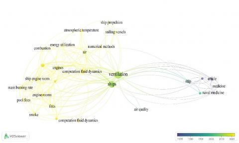
Figure 2 illustrates the growing trend of research pertaining to ship ventilation. The most recent study indicates that the angular movement of hydrogen, in conjunction with mechanical ventilation, has an impact on accidental fires or accidents in the engine room and fuel [63]. To predict hydrogen leaks or explosions in ship engine rooms, the CFD approach, depicted in yellow in Figure 3, is widely employed [64-66]. Further investigation is required to ensure safety and prevent leaks on ships utilizing hydrogen fuel. It is crucial to develop safety guidelines and prevention strategies both before and after accidents occur. While there has been extensive research on leaks using experimental methods or CFD simulations [67-69], there is still a shortage of research on the influence of ship movements and varying air ventilation on leaks or fires in hydrogen-powered ships. This gap presents a promising avenue for future research for scholars interested in air ventilation in vessels powered by hydrogen fuel.
Figure 2. Number of annual publications in the Scopus database with the keyword "ship ventilation"
Figure 3. An overlay map related to the keyword "ship ventilation" theme
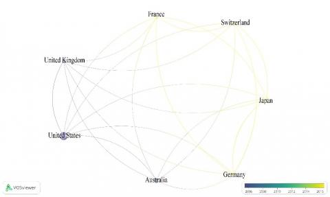
Figure 4. Time overlay visualization of the author's country of origin on the ship ventilation theme
Figure 3, highlighted in yellow, presents a comprehensive discussion of numerous theoretical and experimental studies on ventilation in ship engine rooms. One such study utilizes simulation and experimentation to predict the height of smoke in engine rooms with forced air ventilation [70]. Additionally, a report on the combustion rate and flame in an engine room with two-way air ventilation was conducted experimentally [71]. The simulation modeling of heat transfer in ship engine rooms proves to be a captivating area of study for enhancing air ventilation performance [72]. Due to its pressing nature, the smoke and fire control system implemented on ships has garnered significant attention from researchers [73]. In order to manage smoke in the engine room, it is crucial to regulate smoke exhaust ventilation and the supply of air into the ship's engine room. In the event of a sudden fire, the smoke control system is activated, facilitating the automatic flow of smoke out of the room.
Recent researchers have shown a significant interest in studying ship engine fires, as indicated by Figure 3, highlighted in yellow. Their research's main focus has been understanding the causes and consequences of these accidents [3]. It has been observed that marine fuel leaks from diesel supplies or other liquid fuels are the primary culprits behind these fires, which are frequently encountered [4]. To effectively address this issue, it is crucial to have a well-designed initial framework for the ship's bottom, which can serve as a simulation platform. This framework not only aids in controlling fires that may occur at the bottom but also serves as a reference for safety management before, during, and after a fire incident [74]. Wu et al. [75] comprehensively reviewed probabilistic models in ship fires. These models employ numerical simulation techniques to analyze fire dynamics. It is important to note that the fire process in the engine room differs from that in the cabin. Therefore, understanding the process of extinguishing fires in the engine room is critical to ensuring ship safety. Wu et al. [75] reported on their experiments involving flame temperature gradient testing in the engine room. They conducted tests to measure the temperature gradient of the fire as its size increased.
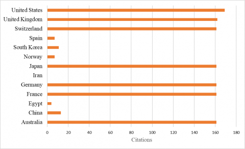
Figure 4, a visual representation of the time overlay on the website, illustrates the categories of countries that engage in publishing articles regarding ship ventilation. Notably, the United States has published many documents, followed by Australia, the United Kingdom, France, Germany, Japan, and Switzerland. On the other hand, Figure 4 highlights that Japan, Switzerland, France, and Germany have published a significant amount of research in 2020 and beyond, as indicated by the yellow color. This research primarily focuses on cabin air ventilation, engine room ventilation, engine leaks, fuel leaks, and safety measures before and after a fire, and it employs simulation or experimental approaches. Furthermore, discussions pertaining to fuel fires from diesel fuel and hydrogen are continuously evolving. Figure 5 displays the number of research citations in each country regarding air ventilation studies. The United States is the country with the highest number of research citations. Specifically, the United States has 169 citations, followed by the United Kingdom with 162 citations, and Australia and Switzerland with an equal number of 161 citations. This substantial number of citations signifies a growing emphasis on research and development in ship ventilation.
Figure 5. Number of author citations in each country
5.1 Eco-friendly marine power system using liquefied natural gas (LNG) waste with cold air ventilation
The investigation conducted by Ahn et al. [76] focused on refrigerating LNG waste to remove heat and maintain a safe condition in the cargo space. The cargo ship in question utilized a ship power system that combines steam and electricity from gas turbine systems. A cold air ventilation flow system was employed, which underwent energy and exergy analysis and a greenhouse gas emission approach. The efficiency of the cooled air ventilation system is remarkably high, boasting a coefficient of performance that is twice as efficient as conventional systems. Moreover, the exergy value experiences an increase as the ventilation airflow is augmented. Consequently, using waste LNG energy as a cooling source proves to be highly beneficial in reducing greenhouse gas emissions. The electrical efficiency calculation (ξelec) takes into account the lower heating value (LHV) of LNG, which is approximately 42,850 kJ/kg as follows:
$\xi_{{elec }}=\frac{\dot{W}_{{net }}}{\dot{m}_f \times L H V_f} \times 100 \%$ (1)
where, $\dot{W}_{n e t}$ (kW) is the net power released in this system, $\dot{m}_f$ (kg/s) is the mass flow of fuel consumption in the marine propulsion system. $\dot{W}_{n e t}$ can be calculated as follows:
$\dot{W}_{ {net }}=\dot{W}_{G T}+\dot{W}_{S T}- \left(\dot{W}_{ {R-pump }}+\dot{W}_{f- { pump }}+\dot{W}_{E G W}\right)$ (2)
$\dot{W}_{ {net }}=\dot{W}_{G T}+\dot{W}_{S T}- \left(\dot{W}_{ {R-pump }}+\dot{W}_{f- { pump }}+\dot{W}_{ {sea-pump }}+\dot{W}_{ {air-comp }}\right)$ (3)
The equation for power consumption ($\dot{W}_X$) on a rotary machine with rotary equipment type (X) is as follows:
$\dot{W}_X=\dot{m}\left(h_o-h_i\right)$ (4)
The energy equation for heat exchange in low- and high-temperature fluids is as follows:
$\dot{m}_{ {hot }, { in }} h_{ {hot }}+\dot{m}_{ {cold,in }} h_{ {cold,in }} =\dot{m}_{ {hot,out }} h_{ {hot,out }}+\dot{m}_{ {cold,out }} h_{ {cold,out }}$ (5)
The coefficient of performance (COP) is the ratio between the input power and the heat dissipation power in the cargo hold, which can be calculated as follows:
$COP =\frac{\dot{Q}_{ {output }}}{\dot{W}_{ {input }}}$ (6)
The exergy calculation in this system [77] is as follows:
$\dot{E}_x=\dot{m}\left(e x_{p h}+e x_{c h}\right)$ (7)
$e x_{p h}=\left(h-h_0\right)-T_0\left(s-s_0\right)$ (8)
$e x_{c h}=\sum \frac{x_i \times e_{i, c h}^{\sim 0}}{M_i}$ (9)
$\xi_{{exergy }}=\frac{\dot{E} x_{ {out }}}{\dot{E} x_{ {input }}} \times 100 \%$ (10)
where, exch is the specific chemical exergy, exph is the specific physical exergy of the system, Mi is the molecular weight, $e_{i, c h}^{\sim 0}$ is the standard molar chemical exergy, xi is the function of the mole fraction, and ξexergy is the efficiency exergy, which is the ratio between exergy input ($\dot{E} x_{ {input }}$) and output ($\dot{E} x_{ {out}}$) of the system.
An eco-efficiency approach to ships is explored in the context of sustainable development in the maritime sector [78]. One method involves calculating the energy efficiency design index (EEDI) for the system [79], as described in the following calculation:
$E E D I_{ {reference \,line }}=174.22 \times(D W T)^{-0.201}$ (11)
$Required \,EEDI =\left(1-\frac{X}{100}\right) \times E E D I_{ {reference \,line }}$ (12)
$Attained \,EEDI =C_F \times \frac{S F C_{M E} \times \sum_i P_{M E}+S F C_{A E} \times P_{A E}}{0.7 \times D W T \times V_{r e f}}$ (13)
$P_{A E}=\left[ 0.025 \times\left(\sum_{i=1} M C R_{M E(i)}+\frac{\left(\sum_i P_{P T I(i)}\right)}{0.75}\right)\right]+250$ (14)
where, CF represents a dimensionless CO2 emission conversion factor, DWT denotes ship weight, and SFCAE and SFCAE are the specific fuel consumption levels in kg/kWh for the main and auxiliary propulsion engines [80].
5.2 The effect of mechanical air ventilation on ship engine room temperature on a large scale
Wu et al. [81] conducted a study on the combustion rate and smoke temperature in the air ventilation of ship engine rooms. The height variations of the inlet air ventilation duct range from 0.1 meter to 1.0 meter, while the time variations span six levels from 38 per hour to 126 per hour. The research findings indicate that the average ventilation level impacts the combustion temperature rate in the engine room. As the ventilation air rate increases, the average temperature of the engine room decreases. Mathematical models are employed to forecast the average temperature of the engine room based on the energy balance principle. Mechanical ventilation in ship engine rooms has two distinct heat transfer effects on fires in ship engine rooms: the cooling effect and the combustion intensification effect. The fire conservation heat equation in a ship's engine room can be calculated as follows:
$\dot{Q}=\dot{Q}_{g a s}+\dot{Q}_e+\dot{Q}_w$ (15)
The gas heating rate, denoted as $\dot{Q}_{gas}$, is accompanied by the heat dispersion rate of smoke in the exhaust, represented as $\dot{Q}_{e}$, the heat dispersion rate of the insulation, indicated as $\dot{Q}_{W}$, and the heat release process in a room fire, labeled as $\dot{Q}$. The average gas heat can be calculated as follows:
$\dot{Q}_{ {gas }}=d\left(c_p \rho_{ {gas }} V T_{ {gas }}\right) / d t$ (16)
$\dot{Q}_e=c_p \dot{m}_{e x}\left(T_{e x}-T_{i n}\right)$ (17)
$\dot{Q}_w=h_T A_T\left(T_{g a s}-T_{i n}\right)$ (18)
The volume of the ship's engine room, denoted as V, along with the heat capacity of the gas, denoted as cp, and the density of the gas in the engine room, denoted as ρgas, play a crucial role in this calculation. Additionally, the average mass flow of smoke coming out of the engine room, represented as $\dot{m}_{e x}$, is taken into consideration. The heat transfer coefficient for the partition, hT, and the total surface area of the partition in the room, AT, are also important factors in this equation. By incorporating all these variables, the heat balance equation in the engine room can be calculated using the following equation:
$\dot{Q}=c_p \dot{m}_{e x}\left(T_{e x}-T_{i n}\right)+h_T A_T\left(T_{g a s}-T_{i n}\right)$ (19)
The heat conservation equation in the engine room can be calculated by balancing the mass flow of smoke out and fresh air entering the room. This result can be achieved through the combination of the equations mentioned as follows:
$T_{g a s}-T_{i n}=T_{e x}-T_{i n}$ dan $\dot{m}_{e x}=\dot{m}_{i n}=\rho_{i n} V . n$ (20)
$\dot{Q}=\left(c_p \dot{m}_{ {ex }}+h_T A_T\right)\left(T_g-T_{ {in }}\right)$ (21)
Zhang et al. [82] discovered the mechanical ventilation heat transfer coefficient (hT).
$h_T=0.0035 \dot{Q}^{1 / 3}$ (22)
$h_T=1 / A_T\left[\dot{Q} /\left(T_{\text {gas }}-T_{i n}\right)-c_p \rho_{\text {in }} V_n\right]$ (23)
$h_T=k_{T n}=6.93 \times 10^{-4} n$ (24)
The average fire temperature in the ship's engine room under quasi-steady state conditions can be calculated as follows:
$T_{g a s}=T_{i n}+\dot{Q} /\left(c_p \dot{m}_{e x}+h_T A_T\right)=T_{i n}+\frac{\chi A_f \Delta H_c}{c_p \rho_{i n} V+k_T A_T}\left(\frac{\dot{m}_0^{\prime \prime}}{n}+R_n\right)$ (25)
$\begin{gathered}T_{\text {gas }}=35^o+46.57\left[\frac{19.75}{n}+\frac{428.99+e^{(115-n / 12.34)}}{3600}\right] \\ 38 h^{-1} \leq n \leq 126 h^{-1}\end{gathered}$ (26)
5.3 Smoke and flame characteristics in the engine room air vents of marine vessels
Numerical investigations conducted by Lan et al. [83] explored the impact of ventilation location and airflow velocity on fire and smoke distribution within ship engine compartments. The study's findings reveal that increased ventilation airflow velocity influences the cooling rate within the ship's engine room. Method 3, which involves placing the intake at the middle of the top side and the exhaust at the bottom, is identified as a more effective ventilation configuration for enhancing the safety of the ship's engine and associated equipment. This research is a valuable resource for optimizing ship ventilation systems and ensuring the safety of ship equipment through simulation techniques.
The heat release rate per unit volume can be calculated based on the mass production rate of components and the mass of the heat source, as expressed by the following equation:
$q^{\prime \prime \prime}=\sum_a m_a^{\prime \prime \prime} \Delta h_{f, a}$ (27)
where, ∆hf,a is the heat generator component, $m_a^{\prime \prime \prime}$ is the average chemical mass value, and q''' is the average heat released per unit volume.
The general equation for determining a hydrocarbon fuel fire's heat transfer rate involves calculating the ignition source and the air parameters within the cabin, as described in the following equation.
$Q=m_{f, \infty}\left(1-e^{k D}\right) \Delta H X_{\text {chem }} \pi D^2 / 4$ (28)
where, Xchem is the combustion efficiency rate, ∆H is the net heat of combustion, D is the pool diameter, k is the absorption rate coefficient, mf,∞ is the mass rate of asymptomatic combustion, and Q is the release rate of the chemical heat.
The equation for the flame height model is as follows:
$\begin{gathered}\frac{H_f}{D}=3.7 Q^{* 2 / 5}-1.02 \\ \text { with, } Q^*=Q / \rho_o C_p T_{\infty}\left(g D^5\right)^{1 / 2}\end{gathered}$ (29)
where, Q is the average heat release from the fire, ρo is the environmental air density, Cp is the air heat capacity, T∞ is the environmental temperature, and g is the gravitational acceleration.
It is essential to calculate the flame source diameter to mesh size ratio, thereby evaluating the mesh resolution [84].
$D^*=\left(\dot{Q} / \rho_0 c_p T_{\infty \sqrt{g}}\right)^{2 / 5}$ (30)
where, $\dot{Q}$ is the average total heat released by the fire, and $D^*$ is the characteristic diameter of the fire.
5.4 Effect of air ventilation in the marine engine room on flame and hot-surface ignition (HSI)
Wang et al. [85] conducted a study on the detection of fuel leaks in the engine room and investigated the behavior of flames on hot surfaces under different ventilation airflow velocities. The experimental approach involves varying the airspeed from 1 m/s to 5 m/s. It was found that the impact of flammable fuels on ignition and flame propagation intensifies with an increase in airflow velocity. The position of the installed air vent influences the leak's location in the ship's engine room. Additionally, the airflow conditions in the engine room decrease as the surface heat temperatures rise. In the steady state, the heat transfer coefficient equation, denoted as hn, can be expressed as follows [86].
$h_n=0.425\left[\frac{k_{v f}^3 H_{f g} \rho_v \rho_L^{3 / 2} g}{\left(T_w-T_{s a t}\right) \mu_{v f} \sigma^{1 / 2}}\right]^{1 / 4}$ (31)
where, hn (W/m2.K) is the heat transfer coefficient at the nuclear point, Kvf (W/m.K) is the conductivity of hot vapor in the film, σ (mN/m) is the surface tension of liquids, μvf (Pa.s) is the vapor viscosity between walls and liquid, Hfg (J/kg.K) is the latent heat of vaporization, ρL (kg/m3) is the liquid fuel density, and ρv (kg/m3) is the fuel vapor density.
$m_F=h_F c_{p, g}^{-1} A \ln (B+1)$ (32)
$b=h_{f g}^{-1} c_{p, g}\left(T_w-T_b\right)$ (33)
where, mF (gm/s) is the average fuel evaporation mass, and B is the mass transfer number. The relationship between the height of heat impact surface (HIS) and the surface temperature can be determined using the following equation:
$H=H_{max }+\frac{T_m}{\sqrt{0.0716 \pi T_s}} \exp \left[-\frac{\ln \left(\frac{T_s}{T_{min }}\right)^2}{46.875 H_{ {min }}}\right]$ (34)
where, Hmax (m) is the initial flame height, Tm (℃) is the average change in surface heat temperature, Ts (℃) is the surface heat temperature, Tmin (℃) is the initial surface temperature, and Hmin (m) is the height of the ship's fuel during the stationary period.
5.5 Smoke height in the ship engine room with experimental and theoretical approaches
Wu et al. [70] conducted a study to assess the height of the smoke layer in a ship's engine room equipped with forced air ventilation. Both experimental and theoretical approaches were employed to investigate the impact of air volume and air height on the ship's engine room. The findings of the tests indicate that an increase in air volume within the ventilation system influences the fire source's mass rate and the smoke layer's height in the engine room. A comparison between the theoretical predictions and experimental results reveals a relative error of approximately 11% in estimating the height of the smoke layer during fires in both the engine room and cabin.
The conservation concept utilized to formulate an equation for predicting the height of the smoke layer in the engine room is as follows:
$\dot{m}_p+\dot{m}_b-\dot{m}_e=\frac{d \rho_s V_u}{d t}$ (35)
where, $\dot{m}_p$ represents the mass flow rate of smoke entering the top control from the fire source, $\dot{m}_b$ represents the mass flow rate of air entering the smoke layer, $\dot{m}_e$ represents the mass flow rate of smoke coming out of the mechanical exhaust, ρs represents the density value of smoke, and Vu represents the volume of the smoke layer in the ship's space. The thickness of the smoke layer at any time $\frac{d Z_u}{d t}$ can be calculated using the following equation:
$\frac{d Z_u}{d t}=\frac{\dot{m}_p+\dot{m}_b-\dot{m}_e}{A_z \rho_s}$ (36)
The plume model adheres to the law of conservation of mass, which is encapsulated by the following equation:
$\dot{m}_p=0.21\left(\frac{\rho_0 g}{C_p T_0}\right)^{1 / 3} \dot{Q}_C^{1 / 3} Z^{5 / 3}=C \dot{Q}_C^{1 / 3} Z^{5 / 3}$ (37)
where, ρo represents the air density, g denotes the acceleration of gravity, Cp represents the heat capacity at constant pressure, To represents the ambient temperature, $\dot{Q}$ represents the ignition power convection, and Z represents the height of the smoke from the surface of the fire. The mass loss rate of a fire source is expressed as follows:
$\dot{m}=f\left(V_s\right)$ (38)
$\dot{Q}_c=\approx 0.7 \dot{Q}=0.7 \chi \cdot f\left(V_s\right) \cdot \Delta H_c$ (39)
where, $\Delta H_c$ is the heat of combustion, $\chi$ is the combustion efficiency, and $\dot{Q}_c$ denotes the total average of the heat output from the fire source.
$\dot{m}_b=\psi \dot{m}_s=g(h) \dot{m}_s=g(h) \rho_s V_s$ (40)
The source of fire under different air volume conditions for determining the smoke layer can be determined as follows:
$\begin{gathered}\frac{d Z_t}{d t}=-\frac{C\left[0.7 \chi\left(-204.54 e^{-\frac{V_S}{0.37}}+7.11\right) \Delta H_c\right]^{1 / 3} z^{5 / 3}+\psi V_s \rho_a-V_e \rho_s}{(k z+b) \rho_s} \\ \text{when} \,t=0, Z_t=1.9\end{gathered}$ (41)
In the case of C, the Zukoski model was employed with a specific value of C=0.076432. As for k, an independent compartment structure was adopted with a value of k=6.7. Similarly, b also follows an independent compartment structure with a value of b=51. In addition, $\psi$ represents the average level of air mixing, and $g(h)=-0.25 e^{-\frac{h}{0.64}}+0.76$.
5.6 Smoke filling and fire entry of the enclosed ship engine room
Wang et al. [87] investigated the behavior of smoke plumes as they entered and filled a ship's engine room in a closed environment. Both theoretical and experimental methods were utilized to examine the smoke inlet channel and the process of smoke filling within the ship's engine room. The findings of this study were corroborated by earlier research, indicating that sealed fires are more likely to result in smoke infiltration compared to open fires. The change in pressure ∆P=P-P0 within a closed ship's engine room due to fire [87] is expressed as follows:
$\frac{\Delta P}{P_0}=\frac{\int_0^t\left(1-\chi_l \dot{Q}(t)\right) d t}{\rho_0 V_{c v} T_0}$ (42)
$\rho_u A(H-z)+\rho_l A_z=\rho_0 A H$ (43)
where, $\dot{Q}(t)$ represents the fire's heat release rate, $\chi_l$ denotes the overall heat loss fraction, ρ0 stands for the initial density of the air, P0 signifies the environmental pressure of the air, ρu indicates the average density of the upper layer of smoke, and ρl represents the average density of the lower layer of smoke.
The following equation can be used for determining the smoke height [15]:
$\frac{d z}{d t}=\frac{-R_M\left(\dot{m}_p c_p T_l+\frac{Z}{H}\left(1-\chi_l\right) \dot{Q}(t)\right)}{P A_{C v}}$ (44)
The equation for the mass flow rate of a plume of smoke at a certain height can be written as follows:
$\dot{m}_p=\rho_0 \pi b_u^2 u_0$ (45)
The equation for the mass flow rate of the smoke plume can be determined in the following manner [16]:
$\dot{m}_p=\frac{1}{C_T \beta}\left[\frac{g \rho_1^2}{c_p T_l}\right]^{1 / 3} Q_c^{1 / 3}\left(z-z_0\right)^{5 / 3}\left[1+C_T(1-\right. \left.\beta)\left(g^{1 / 2} c_p \rho_l T_l\right)^{-2 / 3} Q_c^{2 / 3}\left(z-z_0\right)^{-5 / 3}\right]$ (46)
The Heskestad model equation for Z0 can be calculated as follows [88]:
$\frac{Z_0}{D}=-1.02+0.083 \dot{Q}^{* 2 / 5}$ (47)
where, D represents the diameter of the flame source or the diameter of the non-circular case. The dimensional heat release rate, denoted as $\dot{Q}^*$, can be calculated using the following equation:
$\dot{Q}^*=\frac{\dot{Q}}{\rho_l c_p T_l g^{1 / 2} D^{5 / 2}}$ (48)
The ventilation system aboard a vessel is crucial to ensuring the comfort and safety of passengers and crew members. It is designed to supply adequate fresh air while maintaining optimal air quality throughout various sections of the ship, including the engine room. The ventilation system helps mitigate potential hazards such as leaks and fires by regulating temperature and reducing heat buildup. Ventilation requirements for different ship compartments are categorized into general, specific, and special ship ventilation requirements. It is important to note that all air ventilation compartment requirements on ships adhere to international regulations, classification society rules, and IMO rules.
According to the findings of the bibliometric analysis conducted using VOSViewer, research on air ventilation in ships has emerged as a highly intriguing area of study. This research primarily focuses on the crucial aspects of ship safety and security. Recently, several keywords such as "ventilation," "ship," "CFD," "ship engine," and "fire" have been frequently observed. CFD studies encompass a wide range of simulations related to fuel leaks in the engine room, optimal air ventilation models within the room, and the impact of air ventilation on the engine room. The keywords related to the ship engine room extensively explore fire patterns in ship engines during a fire, the influence of air ventilation on ship engine fires, and heat transfer models incorporating air ventilation.
These current keywords indicate significant prospects for future research, particularly in air ventilation and ship fires. Using mathematical modeling, this review aims to provide a comprehensive overview of variables or parameters that can be utilized to calculate the behavior or progression of smoke or fire in a ship's engine room during a fire incident. Additionally, it aims to predict the effects of air ventilation on fuel leak patterns in the ship's engine room and determine the characteristics of ventilation positions, air quality, and air velocity during fires in shipping vessels. By doing so, researchers can develop more effective and efficient future studies in air ventilation, leaks, fires, and ship accidents, benefiting the maritime community greatly.
[1] Sandle, T. (2020). Review of the efficacy of HEPA filtered air to control coronavirus risks in cleanrooms. European Journal of Parenteral and Pharmaceutical Sciences, 25(2). http://doi.org/10.37521/25203
[2] Romanian Standardization Association. SR ISO 7547, Shipbuilding—Air-Conditioning and Ventilation of Accommodation Spaces on Board Ships—Design Conditions and Basis of Calculations. Romanian Standardization Association: Bucharest, Romania, 2005. https://www.iso.org/standard/76611.html.
[3] Li, C., Zhang, H., Zhang, Y., Kang, J. (2022). Fire risk assessment of a ship’s power system under the conditions of an engine room fire. Journal of Marine Science and Engineering, 10(11): 1658. https://doi.org/10.3390/jmse10111658
[4] Li, C., Mao, J., Kang, Z., Zhao, S., Ren, H. (2023). Influence of firefighting intervention on fire spread characteristics in ship engine room. Journal of Marine Science and Engineering, 11(4): 877. https://doi.org/10.3390/jmse11040877
[5] Vukelic, G., Ogrizovic, D., Bernecic, D., Glujic, D., Vizentin, G. (2023). Application of VR technology for maritime firefighting and evacuation training—A review. Journal of Marine Science and Engineering, 11(9): 1732. https://doi.org/10.3390/jmse11091732
[6] Zhang, H., Li, C., Zhao, N., Chen, B.Q., Ren, H., Kang, J. (2022). Fire risk assessment in engine rooms considering the fire-induced domino effects. Journal of Marine Science and Engineering, 10(11): 1685. https://doi.org/10.3390/jmse10111685
[7] McNay, J., Puisa, R., Vassalos, D. (2019). Analysis of effectiveness of fire safety in machinery spaces. Fire Safety Journal, 108: 102859. https://doi.org/10.1016/j.firesaf.2019.102859
[8] Baalisampang, T., Abbassi, R., Garaniya, V., Khan, F., Dadashzadeh, M. (2018). Review and analysis of fire and explosion accidents in maritime transportation. Ocean Engineering, 158: 350-366. https://doi.org/10.1016/j.oceaneng.2018.04.022
[9] Su, S., Wang, L. (2013). Three dimensional reconstruction of the fire in a ship engine room with multilayer structures. Ocean Engineering, 70: 201-207. https://doi.org/10.1016/j.oceaneng.2013.05.032
[10] Wang, J., Jiao, Y., Shi, L., Xie, Q., Li, G., Liu, J., Chen, W., Zhang, S. (2018). An experimental and non-dimensional study on the vertical temperature distribution of a sealed ship engine room fire. Ocean Engineering, 165: 22-33. https://doi.org/10.1016/j.oceaneng.2018.07.018
[11] Chow, W.K., Zou, G.W. (2009). Numerical simulation of pressure changes in closed chamber fires. Building and Environment, 44(6): 1261-1275. https://doi.org/10.1016/j.buildenv.2008.09.016
[12] Li, J., Beji, T., Brohez, S., Merci, B. (2021). Experimental and numerical study of pool fire dynamics in an air-tight compartment focusing on pressure variation. Fire Safety Journal, 120: 103128. https://doi.org/10.1016/j.firesaf.2020.103128
[13] Pearson, A., Most, J.M., Drysdale, D. (2007). Behaviour of a confined fire located in an unventilated zone. In Proceedings of the Combustion Institute, 31(2): 2529-2536. https://doi.org/10.1016/j.proci.2006.08.019
[14] Prétrel, H., Le Saux, W., Audouin, L. (2012). Pressure variations induced by a pool fire in a well-confined and force-ventilated compartment. Fire Safety Journal, 52: 11-24. https://doi.org/10.1016/j.firesaf.2012.04.005
[15] Morton, B.R. (1965). Modeling fire plumes. In Symposium (International) on Combustion, 10(1): 973-982. https://doi.org/10.1016/S0082-0784(65)80240-5
[16] Heskestad, G. (1988). Fire plume air entrainment according to two competing assumptions. In Symposium (International) on Combustion, 21(1): 111-120. https://doi.org/10.1016/S0082-0784(88)80237-6
[17] McCaffrey, B.J. (1983). Momentum implications for buoyant diffusion flames. Combustion and Flame, 52: 149-167. https://doi.org/10.1016/0010-2180(83)90129-3
[18] Vaux, S., Mehaddi, R., Collin, A., Boulet, P. (2021). Fire plume in a sharply stratified ambient fluid. Fire Technology, 57(4): 1969-1986. https://doi.org/10.1007/s10694-021-01100-6
[19] Mehaddi, R., Candelier, F., Vauquelin, O. (2013). Naturally bounded plumes. Journal of Fluid Mechanics, 717: 472-483. https://doi.org/10.1017/jfm.2012.587
[20] Ciriello, F., Hunt, G.R. (2020). Analytical solutions and virtual origin corrections for forced, pure and lazy turbulent plumes based on a universal entrainment function. Journal of Fluid Mechanics, 893: A12. https://doi.org/10.1017/jfm.2020.225
[21] Vauquelin, O. (2015). Oscillatory behaviour in an emptying–filling box. Journal of Fluid Mechanics, 781: 712-726. https://doi.org/10.1017/jfm.2015.518
[22] Vauquelin, O., Koutaiba, E.M., Blanchard, E., Fromy, P. (2017). The discharge plume parameter and its implications for an emptying-filling box. Journal of Fluid Mechanics, 817: 171-182. https://doi.org/10.1017/jfm.2017.130
[23] Kaye, N.B., Hunt, G.R. (2007). Smoke filling time for a room due to a small fire: the effect of ceiling height to floor width aspect ratio. Fire Safety Journal, 42(5): 329-339. https://doi.org/10.1016/j.firesaf.2006.12.003
[24] Young, Y.L., Harwood, C.M., Miguel Montero, F., Ward, J.C., Ceccio, S.L. (2017). Ventilation of lifting bodies: Review of the physics and discussion of scaling effects. Applied Mechanics Reviews, 69(1): 010801. https://doi.org/10.1115/1.4035360
[25] Mihai, V., Rusu, L. (2021). An overview of the ship ventilation systems and measures to avoid the spread of diseases. Inventions, 6(3): 55. https://doi.org/10.3390/inventions6030055
[26] Arshad, H., Emblemsvåg, J., Li, G., Ostnes, R. (2022). Determinants, methods, and solutions of evacuation models for passenger ships: A systematic literature review. Ocean Engineering, 263: 112371. https://doi.org/10.1016/j.oceaneng.2022.112371
[27] Vukelic, G., Ogrizovic, D., Bernecic, D., Glujic, D., Vizentin, G. (2023). Application of VR technology for maritime firefighting and evacuation training—A review. Journal of Marine Science and Engineering, 11(9): 1732. https://doi.org/10.3390/jmse11091732
[28] Lloyd, D.N.V. (2014). Seagoing ships—21 Ventilation. Available online: https://rules.dnv.com/docs/pdf/gl/maritimerules/gl_i-1-21_e.pdf.
[29] BV Marine & Offshore Division, NR529 DT R03 E—Gas Fuelled Ships; BV Marine & Offshore Division. Neuilly-sur-Seine, France, 2020 https://marine-offshore.bureauveritas.com/nr529-gas-fuelled-ships.
[30] BV Marine & Offshore Division, NR 467 D1 DT R12 E—Part D—Service Notations; BV Marine & Offshore Division. Neuilly-sur-Seine, France, 2020. https://marine-offshore.bureauveritas.com/nr467-rules-classification-steel-ships.
[31] International Maritime Organization—IMO. Load Lines, 1966/1988—International Convention on Load Lines, 1966, as Amended by the Protocol of 1988; Lloyd’s Register Rulefinder 2020—Version 9.33—Fix; International Maritime Organization: London, UK, 2014, 2014 https://www.imo.org/en/About/Conventions/Pages/International-Convention-on-Load-Lines.aspx.
[32] Zender-Świercz, E. (2021). A review of heat recovery in ventilation. Energies, 14(6): 1759. https://doi.org/10.3390/en14061759
[33] International Maritime Organization—IMO. SOLAS, International Convention for the Safety of Life at Sea. Lloyd's Register Rulefinder, 2020. https://www.imo.org/en/KnowledgeCentre/ConferencesMeetings/Pages/SOLAS.aspx.
[34] BV Marine & Offshore Division, NR 467 B1 DT R12 E—Part B—Hull and Stability; BV Marine & Offshore Division. Neuilly-sur-Seine, France, 2020. https://marine-offshore.bureauveritas.com/nr467-rules-classification-steel-ships.
[35] RINA. Part B Vol. 3, Hull and Stability. Rules for the Classification of Ships. RINA: Chita, Japan, 2021. https://www.rina.org/en/rules.
[36] RINA. Part E Vol. 2, Service Notation. Rules for the Classification of Ships. RINA: Chita, Japan, 2021. https://www.rina.org/en/rules.
[37] International Association of Classification—IACS. S27, Strength Requirements for Fore Deck Fittings and Equipment, 2013. https://iacs.org.uk/resolutions/unified-requirements/ur-s/ur-s27-rev6-cln, 2013.
[38] BV Marine & Offshore Division, NR529 DT R03 E—Gas Fuelled Ships. BV Marine & Offshore Division: Neuilly-sur-Seine, France, 2020. https://marine-offshore.bureauveritas.com/nr529-gas-fuelled-ships.
[39] Romanian Standardization Association, SR ISO 8861, Shipbuilding—Engine Room Ventilation in Diesel-Engined Ships—Design Requirements and Basis of Calculations. Romanian Standardization Association: Bucharest, Romania, 2002. https://www.iso.org/standard/25519.html.
[40] International Association of Classification—IACS, UR-M28 Requirements Concerning Machinery Installations—Ambient Reference Conditions. International Association of Classification: Kolkata, India, 1978. https://iacs.org.uk/resolutions/unified-requirements/ur-e.
[41] International Association of Classification—IACS, UR-M40, Ambient Conditions—Temperatures, Kolkata, India, 1986.
[42] Mihai, V., Rusu, L., Presura, A. (2020). Ventilation of engine rooms in diesel engines ships. Annals of the University Dunarea de Jos of Galati: Fascicle XI, Shipbuilding.
[43] RINA Part C Vol. 1, Machinery, Systems and Fire Protection. Rules for the Classification of Ships. RINA: Chita, Japan, 2021. https://www.rina.org/en/rules.
[44] Romanian Standardization Association, SR ISO 7547-Ships and marine technology — Air-conditioning and ventilation of accommodation spaces and other enclosed compartments on board ships — Design conditions and basis of calculations. Romanian Standardization Association: Bucharest, Romania, 2022. https://www.iso.org/standard/76611.html.
[45] RINA Part C Vol. 2, Machinery, Systems and Fire Protection. Rules for the Classification of Ships. RINA: Chita, Japan, 2021. https://www.rina.org/en/rules.
[46] Romanian Standardization Association, SR ISO 9943—Shipbuilding—Ventilation and Air-Treatment of Galleys and Pantries with Cooking Appliances. Romanian Standardization Association: Bucharest, Romania, 2009. https://www.iso.org/standard/43036.html.
[47] RINA Part E Vol. 3, Service Notations. Rules for the Classification of Ships. RINA: Chita, Japan, 2021. https://www.rina.org/en/rules.
[48] International Maritime Organization—IMO, MSC/Circular.1034—Guidelines for Smoke Control and Ventilation Systems for Internal Assembly Stations and Atriums on New Passenger Ships. Lloyd's Register Rulefinder 2020—Version 9.33—Fix; International Maritime Organization: London, UK, 2020. https://www.imorules.com/MSCCIRC_1034.html.
[49] European Committee for Drawing up Standards in the Field of Inland Navigation. (CESNI), European Standard laying down Technical Requirements for Inland Navigation Vessels (ES-TRIN). CESNI: Strasbourg, France, 2021. https://www.cesni.eu/en/technical-requirements/.
[50] Romanian Standardization Association, SR ISO 9785, Ships and marine technology — Ventilation of cargo spaces where vehicles with internal combustion engines are driven — Calculation of theoretical total airflow required. Romanian Standardization Association: Bucharest, Romania, 2002. https://www.iso.org/standard/27018.html.
[51] BV Marine & Offshore Division, NR527 DT R04 E—Rules for the Classification of Ships Operating in Polar Waters and Icebreakers; BV Marine & Offshore Division. Neuilly-sur-Seine, France, 2021. https://marine-offshore.bureauveritas.com/nr527-rules-classification-ships-operating-polar-waters-and-icebreakers.
[52] Peatross, M.J., Beyler, C.L. (1997). Ventilation effects on compartment fire characterization. Fire Safety Science, 5: 403-414. https://doi.org/10.3801/iafss.fss.5-403
[53] Le Saux, W., Pretrel, H., Lucchesi, C., Guillou, P. (2008). Experimental study of the fire mass loss rate in confined and mechanically ventilated multi-room scenarios. Fire Safety Science, 9: 943-954. https://doi.org/10.3801/IAFSS.FSS.9-943
[54] Foote, K.L., Pagni, P.J., Alvares, N.J. (1986). Temperature correlations for forced-ventilated compartment fires. Fire Safety Science, 1: 139-148. https://doi.org/10.3801/iafss.fss.1-139
[55] Deal, S., Beylert, C. (1990). Correlating preflashover room fire temperatures. Journal of Fire Protection Engineering, 2(2): 33-48. https://doi.org/10.1177/104239159000200201
[56] Chow, W.K. (1993). Modelling of forced-ventilation fires. Mathematical and Computer Modelling, 18(5). https://doi.org/10.1016/0895-7177(93)90133-J
[57] Brohez, S., Caravita, I. (2020). Fire induced pressure in airthigh houses: Experiments and FDS validation. Fire Safety Journal, 114: 103008. https://doi.org/10.1016/j.firesaf.2020.103008
[58] Li, J., Beji, T., Brohez, S., Merci, B. (2020). CFD study of fire-induced pressure variation in a mechanically-ventilated air-tight compartment. Fire Safety Journal, 115: 103012. https://doi.org/10.1016/j.firesaf.2020.103012
[59] Li, J., Pretrel, H., Suard, S., Beji, T., Merci, B. (2021). Experimental study on the effect of mechanical ventilation conditions and fire dynamics on the pressure evolution in an air-tight compartment. Fire Safety Journal, 125: 103426. https://doi.org/10.1016/j.firesaf.2021.103426
[60] Zukoski, E.E. (1978). Development of a stratified ceiling layer in the early stages of a closed-room fire. Fire and Materials, 2(2): 54-62. https://doi.org/10.1002/fam.810020203
[61] Haouari-Harrak, S., Mehaddi, R., Boulet, P., Koutaiba, E.M. (2020). Evaluation of the room smoke filling time for fire plumes: Influence of the room geometry. Fire and Materials, 44(6): 793-803. https://doi.org/10.1002/fam.2873
[62] Zhang, Y., Liu, Z., Lin, Y., Fu, M., Chen, Y. (2020). New approaches to determine the interface height of fire smoke based on a three-layer zone model and its verification in large confined space. Fire and Materials, 44(1): 130-138. https://doi.org/10.1002/fam.2785
[63] Kim, B., Hwang, K.I. (2024). Effect of angular motion on accidental hydrogen fires in conceptional ship fuel preparation room with mechanical ventilation. International Journal of Hydrogen Energy, 50: 1075-1090. https://doi.org/10.1016/j.ijhydene.2023.09.054
[64] Jang, C.B., Choi, S. W., Baek, J.B. (2015). CFD modeling and fire damage analysis of jet fire on hydrogen pipeline in a pipe rack structure. International Journal of Hydrogen Energy, 40(45): 15760-15772. https://doi.org/10.1016/j.ijhydene.2015.09.070
[65] Xie, Y., Lv, N., Wang, X., Wu, D., Wang, S. (2021). Thermal and fire characteristics of hydrogen jet flames in the tunnel at longitudinal ventilation strategies. Fuel, 306: 121659. https://doi.org/10.1016/j.fuel.2021.121659
[66] Gu, X., Zhang, J., Pan, Y., Ni, Y., Ma, C., Zhou, W., Wang, Y. (2020). Hazard analysis on tunnel hydrogen jet fire based on CFD simulation of temperature field and concentration field. Safety Science, 122: 104532. https://doi.org/10.1016/j.ssci.2019.104532
[67] Hooker, P., Hall, J., Hoyes, J.R., Newton, A., Willoughby, D. (2017). Hydrogen jet fires in a passively ventilated enclosure. International Journal of Hydrogen Energy, 42(11): 7577-7588. https://doi.org/10.1016/j.ijhydene.2016.07.246
[68] Lin, H., Luan, H., Yang, L., Han, C., Zhang, S., Zhu, H., Chen, G. (2023). Numerical simulation and consequence analysis of accidental hydrogen fires in a conceptual offshore hydrogen production platform. International Journal of Hydrogen Energy, 48(27): 10250-10263. https://doi.org/10.1016/j.ijhydene.2022.11.349
[69] Yuan, Y., Wu, S., Shen, B. (2021). A numerical simulation of the suppression of hydrogen jet fires on hydrogen fuel cell ships using a fine water mist. International Journal of Hydrogen Energy, 46(24): 13353-13364. https://doi.org/10.1016/j.ijhydene.2021.01.130
[70] Wu, X., Zhang, Y., Jia, J., Chen, X., Yao, W., Lu, S. (2023). Experimental and theoretical analysis of the smoke layer height in the engine room under the forced air condition. Fire, 6(1): 16. https://doi.org/10.3390/fire6010016
[71] Wang, L., Guo, Y., Xia, Z., Lao, X., Su, S., Yuan, Z., Wu, Z. (2023). Experimental study on mass burning rate and flame geometry of pool fires under two-way indirect ventilation in Ship's engine room. Case Studies in Thermal Engineering, 41: 102595. https://doi.org/10.1016/j.csite.2022.102595
[72] Salmani, A., Hosseini, S.F., Khani, H. (2023). Modelling heat transfer and fluid flow in a ship engine room using CFD analysis to evaluate and improve ventilation. Proceedings of the Institution of Mechanical Engineers, Part M: Journal of Engineering for the Maritime Environment, 237(2): 420-435. https://doi.org/10.1177/14750902221118485
[73] El-Helw, M., Fayed, M., El-Shobaky, A. (2018). Studying different scenarios of operating air conditioning system in smoke management using computational fluid dynamics in naval ships. Thermal Science, 22(6 Part B): 2973-2986.
[74] Kang, H.J., Choi, J., Lee, D., Park, B.J. (2017). A framework for using computational fire simulations in the early phases of ship design. Ocean Engineering, 129: 335-342. https://doi.org/10.1016/j.oceaneng.2016.11.018
[75] Wu, B., Zong, L., Yip, T. L., Wang, Y. (2018). A probabilistic model for fatality estimation of ship fire accidents. Ocean Engineering, 170: 266-275. https://doi.org/10.1016/j.oceaneng.2018.10.056
[76] Ahn, J., Park, S. H., Jeong, J., Lee, S., Ryu, J., Park, J. (2021). Eco-efficient marine power system with cooled air ventilation by waste LNG cold energy for reefer holds in an ultra-large container ship. Journal of Cleaner Production, 322: 129037. https://doi.org/10.1016/j.jclepro.2021.129037
[77] Querol, E., Gonzalez-Regueral, B., Perez-Benedito, J. L. (2013). Practical Approach to Exergy and Thermoeconomic Analyses of Industrial Processes. London: Springer.
[78] Ahn, J., Park, S.H., Noh, Y., Choi, B.I., Ryu, J., Chang, D., Brendstrup, K.L.M. (2018). Performance and availability of a marine generator-solid oxide fuel cell-gas turbine hybrid system in a very large ethane carrier. Journal of Power Sources, 399: 199-206. https://doi.org/10.1016/j.jpowsour.2018.07.103
[79] Lützen, M., Mikkelsen, L. L., Jensen, S., Rasmussen, H. B. (2017). Energy efficiency of working vessels–A framework. Journal of Cleaner Production, 143: 90-99. https://doi.org/10.1016/j.jclepro.2016.12.146
[80] Yuan, T., Song, C., Bao, J., Zhang, N., Zhang, X., He, G. (2019). Minimizing power consumption of boil off gas (BOG) recondensation process by power generation using cold energy in liquefied natural gas (LNG) regasification process. Journal of Cleaner Production, 238: 117949. https://doi.org/10.1016/j.jclepro.2019.117949
[81] Wu, X., Yao, W., Jia, J., Chen, X., Lu, S. (2024). Large-scale experimental investigation of effect of mechanical ventilation on smoke temperature in ship engine room. Fire Technology, 60(2): 1287-1311. https://doi.org/10.1007/s10694-022-01331-1
[82] Zhang, J., Lu, S., Li, C., Kit Yuen, R.K. (2015). Performance of overall heat transfer coefficient and exploring heat transfer through the ceiling vent of compartment fire in ship structures with A60 constructions. Ships and Offshore Structures, 10(3): 328-334. https://doi.org/10.1080/17445302.2013.876166
[83] Lan, Q., Han, F., Liu, Y., Li, W., Wang, Z. (2023). Effects of ventilation system design on flame behavior and smoke characteristics for mitigating marine engine room fire hazards. Ocean Engineering, 281: 114890. https://doi.org/10.1016/j.oceaneng.2023.114890
[84] McGrattan, K., Hostikka, S., McDermott, R., Floyd, J., Weinschenk, C., Overholt, K. (2013). Fire dynamics simulator user’s guide. NIST Special Publication, 1019(6): 1-339.
[85] Wang, K., Ming, Y., Liu, X., Wang, H., He, Y. (2023). Effect of lateral airflow on initial HSI and flame behavior of marine fuel in a ship engine room: Experiment and analysis. Journal of Marine Science and Engineering, 12(1): 5.
[86] Song, M., Liu, X., Cheng, X. (2023). Modelling and experimental validation of heat transfer behavior during trans-critical transients. Annals of Nuclear Energy, 186: 109771. https://doi.org/10.1016/j.anucene.2023.109771
[87] Wang, J., Zhang, R., Wang, Y., Shi, L., Zhang, S., Li, C., Zhang, Y., Zhang, Q. (2022). Smoke filling and entrainment behaviors of fire in a sealed ship engine room. Ocean Engineering, 245: 110521. https://doi.org/10.1016/j.oceaneng.2022.110521
[88] Heskestad, G. (1983). Virtual origins of fire plumes. Fire Safety Journal, 5(2): 109-114. https://doi.org/10.1016/0379-7112(83)90003-6