Mayasa M. Abdulrahman![]() | Mohanad Sameer Jabbar
| Mohanad Sameer Jabbar![]() | Ahmad AbdulQadir AlRababah
| Ahmad AbdulQadir AlRababah![]() | Ravi Sekhar*
| Ravi Sekhar*![]() | Pritesh Shah
| Pritesh Shah![]()
© 2024 The authors. This article is published by IIETA and is licensed under the CC BY 4.0 license (http://creativecommons.org/licenses/by/4.0/).
OPEN ACCESS
This paper delves into the recent advancements in phased-array antenna systems, focusing on their application in low earth orbit (LEO) satellite systems and their implications for high-speed, low-latency communication networks. The escalating demand for high-speed data transfer and responsive communication has spurred the exploration of novel antenna technology solutions. In light of meeting these needs, phased-array antenna systems are now giving the prospect of offering something that conventional antenna systems cannot: the capacity to steer building and pathway beams in numerous and precise means to make the most of signal intersection. Realized by the directing and molding strategies, this capability reduces the signal transmission time, which enhances the low latency process in the network hence increases its responsiveness. In addition, the design of phased-array antennas allows increased data rates as it increases network capacity and allows for multiplication of transmission beams to provide faster data processing. The paper also looks into the interaction of these advancements with the LEO satellites, satellites that orbit close to the Earth and move from point to point quite frequently. The issues that arise when implementing LEO systems such as target mobility and communicating with multiple targets, overcoming interference in crowded orbits can be resolved by adopting phased-array antenna systems for resilient infrastructure.
phased-array antennas, low-latency communication, high-speed networks, low earth orbit, satellites, beam steering, resilient infrastructure
The focus of this research work is to seek to understand how they can be said to be a revolution in enabling enhanced communication [1, 2]. Wireless communication networks have a basic makeup that is still under assessment in an effort to meet the ever expanding world of digital structures [3]. It has hence become mandatory to have Phased-Array Antenna Systems in this evolving landscape due to their unmatched ability to dynamically build and point beams, as pointed by Saad et al. [4]. As opposed to traditional phased arrays which require mechanical beam pointing and may lack the agility realized by modern high throughput, low latency networks - the ability to transmit in multiple directions simultaneously is a much sought after feature. Therefore, the current Phased-Array Antenna Systems offers an enticing possibility that provides great opportunities to transform wireless communication as noted in the study conducted by Song et al. [5]. Today, multiple fields such as the aerospace, satellite, and LEO communication rely on phased-array antenna systems. It was also observed that these Very High Frequency Millimeter Wave Technologies specifically possess the capability for dealing with present constraints in high speed communication networks revealed by Jia et al. [6]. More than that, they have demonstrated the fact that they are closely related to exhibiting a significantly reduced latency issues, characteristic of traditional communication channels, thereby stretching the realm of real-time communications. As such, while the following listed potential benefits look appealing, the use of phased-array antenna systems to establish low latency, high speed communication network isn’t that easy. They add that it is common for these advanced systems to be associated with problems like system complexity, costs, signal integrity and power consumption, heat dissipation, among others which Sahni [7] alludes to. It is time to consider LEO satellite networks as a new wireless paradigm shift. These networks have been described to be the next-generation networks that would make internet access available almost anywhere appealing to consumers in terms of location independency, high speed and low latency according to literature [8]. This is due to the fact that the phased-array antenna systems are one of the significant aspects in this advancement in LEO satellite communication. To illustrate, LEO satellites have considerably lower altitudes than those of geostationary satellites, reaching from 500 km to 2000 km, above the earth’s surface, as pointed out by Peterson and Schnaufer [9]. Because the signal has very little delay, the rate according to which data is transmitted also increases greatly. However, because the LEO satellites orbit fast across the sky, perhaps it may be challenging or not straightforward to have consistent communication contact with them. This is especially true since the use of phased-array antenna systems with precise and rapid beam steering and adaptive beam forming as pointed out by Kildal et al. [10] can be quite useful in this regard.
Phased-array antennas enhance communication systems because they can establish beams within response time of several microseconds, which is significantly faster than mechanical engagement. They ensure that inter-symbol interference is less than one millisecond, which is essential for LEO satellite systems and can work with several beams to deliver throughput of several gigabits per second, especially when the network is crowded. In addition, they can also alter the transmission focus and direction of the network beams, enhancing the network’s adaptability and responsivity to the ever-changing conditions, and oscillating high mobility while at the same time providing superior quality signals and strength.
A phased-array system comprises several independent antenna elements that can be steered to alter an airing pattern of an array. The dipole antenna is shows by Zhang et al. [11] as the most common type of component in these arrays. Dipole antennas have an open and omnidirectional radiation pattern and are simple yet effective antenna designs. They are made up of two identical conducting pieces, such as rods or wires, placed end-to-end with a tiny gap in the middle, which is connected to the feed line as mentioned by Liu et al. [12]. Multiple dipole antennas (or dipoles) are placed in a precise pattern when utilized in a phased-array antenna system. Due to the individual controllability of each of these dipoles, the array may concentrate and direct the radiated signal. The total antenna array can produce a beam of radio waves that can be electronically directed in different directions without physically moving the antennas by varying the phase and amplitude of the signal at each dipole as stated by Chen et al. [13]. Phased-array systems are incredibly adaptable because to their ability to steer the beam. The system can use it to follow moving objects (like satellites or aircraft) and quickly switch between different coverage zones. It can also be used to account for wireless communication system signal fading or interference. Dipole antenna integration with phased-array systems has several additional benefits. Dipoles may function across a wide frequency range and are very simple to build. Additionally, they frequently perform with balanced gain, bandwidth, and impedance matching according to the studies conducted by Wu et al. [14] and Xiao et al. [15]. The management of mutual coupling between closely spaced dipoles and the creation of effective feeding networks are two difficulties that come with incorporating them into phased arrays. The study shall examine the use of dipole antennas in phased-array antenna systems in the context of this paper, outlining their functions, benefits, and potential drawbacks. The study shall also take a look at current developments that try to solve problems and take advantage of the advantages of employing dipole antennas to create high-speed, low-latency communication networks. Figure 1 shows a linear array antenna made up of dipole antennas.
Figure 1. Linear phased-array antenna of dipoles
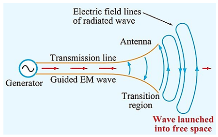
Before exploring the nature and operation of phased-array antennas, it is beneficial to review the characteristics of antennas and the operation of a simple, but very common antenna: the dipole antenna according to Peng et al.’s study [16]. This will provide context and highlight the great advantages of phased-array antennas over any other antenna topology. If we recall the definition, an antenna is a device that acts as a transducer, converting a guided electromagnetic wave into an unbounded electromagnetic wave, as illustrated in Figure 2, or vice versa, depending on the mode of operation: transmitting or receiving. Abstractly, this concept is simple as stated by Ahmed et al. [17]. Concretizing how the transduction can be achieved, is perhaps more difficult. To provide some intuition to this phenomenon, let’s take a look at a circuit element we are familiar with the parallel plate capacitor.
Figure 2. Antenna as wave transducer
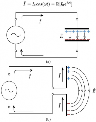
As shown in Figure 3(a), when a capacitor is excited by a current in the clockwise direction, the charge and electric field distribution are generated as shown. If we make a slight modification to this arrangement and connect the wires to the edges of the capacitor and we fold it up and energize it as in Figure 3(b), we can predict an electric field distribution as shown, where the lines follow a path from positive to negative charges.
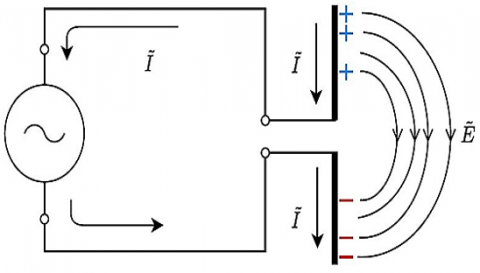
The charge distribution might be more difficult to predict. Applying the free-electron model of conductors, however, we can explain how at the instant the capacitor is energized, the free electrons in the conductors (wires and plates) will get pushed and drift towards the end of the bottom plate. Hence, more charges are expected towards the edges of the plates and the charge distribution will be lower towards the center of the dipole. It is important to note that the direction of current in both plates is the same. As we will see later, this is important as both currents contribute to the generation of a stronger H-field rather than subtract the contributions of each other as mentioned in literatures [18, 19]. When the polarization of the current flips at the source, there’s an instant when the charges have not drifted to the other side quite yet and remain with a similar distribution as in Figure 4.
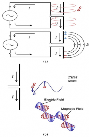
For the frequency range of operation of dipole antennas, the voltage (or charge) distribution and current distribution may or may not have opposite orientation with respect to each other. In any case, the current drives the charge drift, which responds with a certain delay. As we will see in the discussion in Figure 5, this will yield the generation of a forward propagating electromagnetic wave. Applying the right hand rule, as in Figure 5(a), we obtain an H-field coming out of the plane on the right hand side of the dipole. With the E-field lines almost straight at the center of the dipole, we can approximate these two field lines around the center of the dipole to generate the electromagnetic wave in Figure 5(b).
Figure 3. (a) Parallel plate capacitor; (b) Dipole antenna current and E-field direction
Figure 4. Alternate current and charge distribution
Figure 5. (a) E-field and H-field lines; (b) Forward traveling TEM electromagnetic wave
Incorporating performance parameters such as gain, directivity, and efficiency into the techniques section would improve the study of various weighting distributions in phased array antennas. Gain measures the antenna's ability to focus signal power directionally, which is critical for applications requiring precise signal transmission. Directivity evaluates the antenna's effectiveness in focusing energy in a single direction, which is important for targeted beam steering. Efficiency measures how well the antenna converts input power into radiated energy, which affects overall system performance. These measurements are critical for analyzing and improving weighting distributions such as uniform, Hanning, and Taylor, allowing for customized antenna designs to satisfy unique operational needs in communication systems.
3.1 Power propagation - radiation pattern
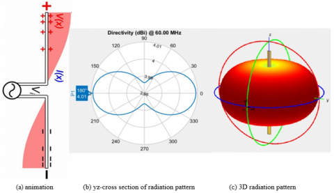
Currently, there is still ongoing investigation on the study of models that can more accurately describe the charge and current distribution of dipole antennas as well as many other antennas. For the purposes of this text, and the overall standards in industry, the existing theory describing the nature of dipoles is in line with the explanation presented above and available in the dipole Wikipedia page. Borrowing an animation from this page of the half-wave dipole antenna ‒ name given because its length is half a wavelength ‒ we proceed to investigate its output radiation pattern. As shown in Figure 6(a). The voltage and current distribution are exactly opposite to each other. When the current is maximum the voltage is zero and vice versa as stated by Wei et al. [20]. The polarities are always opposite as well, when the current is positive, the voltage is negative and vice versa. This is important, because when evaluating the propagation of power within a medium, we use the time-average Poynting Vector, given in Eq. (1).
$S_{a v}=\frac{1}{2} \mathbb{R}\left[\overline{\bar{E}} X \overline{\bar{H}}^*\right]$ (1)
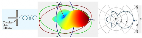
Assuming time harmonic fields, to calculate the propagating power Sav, we cross-multiply the phasor electric field, E, times the conjugate of the phasor magnetic field, H. From the animation, we can predict the power propagation being higher towards the center of the dipole compared to the edges. Using MATLAB’s App: Antenna Designer, we obtain Figure 6(b) and Figure 6(c) which provide an exact illustration of the radiation pattern of a half-wavelength antenna at 60MHz. The same analysis can be performed on different antenna topologies: a helix antenna (Figure 7) or a horn antenna (Figure 8), for example. As shown in these illustrations, the radiation patterns vary in shape and intensity as mentioned by Li et al. [21], Herd and Conway [22]. If a team of RF engineers is to select an antenna for a specific application, they would have to evaluate the desired radiation pattern. If an omnidirectional pattern is desired, as in AM radio for example, the half-wave dipole will work well. If instead, more directivity is needed, as in weather tracking or satellite TV, a helix or horn antenna might be more appropriate. Among these antennas, despite the differences in the radiation pattern, they all have a common feature: their radiation pattern is fixed. The RF engineer, or antenna designer, can do very little to modify the shape of the pattern without compromising other performance parameters as mentioned by Dolph [23]. It is precisely for restrictions in radiation pattern versatility where phased-array antennas offer an outstanding advantage: the ability to control the radiation pattern, to a certain degree, and to do it so on-demand.
Figure 6. Radiation pattern of half-wave dipole antenna at 60MHz
Figure 7. Radiation pattern of a helix antenna
Figure 8. Radiation pattern of a horn antenna
3.2 Phased-array antennas
A flexible radiation pattern is created by the physical concept of wave interference. Wave interference was first seen long ago, and the idea of combining different antennas to create a phased-array antenna is likewise not new. Why is this antenna topology changing the field right now? Phased-array antennas can now be implemented in closed-loop in back end systems, such as transmitter and reception systems, thanks to recent developments in mixed-signal hardware and unique digital signal processing (DSP) techniques according to Al Barazanchi et al.’s study [24]. Without these advancements, the use of these antennas was restricted to resource-intensive, sophisticated projects like the AN/FPS-85 Phased Array Radar station in Florida. Phased-array antennas can now be found in devices as small as a cell phone. In order to understand why and how these antennas are revolutionizing the area of communications, we will start analyzing what is the interference phenomena (Figure 9). Recall that when an isotropic wave source generates omnidirectional waves and these hit a wall with narrow openings, or slits, these become sources of waves themselves. The waves coming from the two slits, will interact and produce the resulting intensity pattern some distance away at the screen. Because at different points in the screen, one of the waves has traveled a different length than the other, there is a relative phase difference between the two waves. The two waves coming together at different points in the screen will interfere constructively or destructively, depending on the relative phase, to produce a sinc function intensity pattern shown in Figure 9. Exploiting this concept, we can replace the slits in the wall by any desired number of physical antennas and utilize the interference phenomena to our advantage.
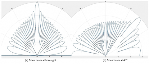
3.2.1 Steering in phased-array antennas
In todays high-speed, low-latency communication networks, phased array antennas play a key role. The phrase "phased array" is used to describe an array of antennas in which the signals fed to each antenna are fed at different phases to boost the radiation in one direction while dampening it in another as stated by Valdes-Garcia et al. [25]. With the concept of wave interference in mind, we can see how directing the main beam to a desired direction is accomplished by manipulating the relative phase of the antennas, as illustrated in Figure 10. Electrically steering the main beam offers the advantage of eliminating a mechanical structure, saving costs, complexity and providing resilience to mechanical failure. The rates at which the beam can be steered are much faster than a rotational system. While the ability of steering the main beam electrically offers great advantages, the shape of the radiation pattern still remains as a sinc-type function, with unwanted side lobes with high power levels. Figure 11 shows the Phased-array illustration
Figure 9. Double-slit experiment illustrating the interference phenomena
Figure 10. Main beam steering by control over the relative phase of each antenna
Figure 11. Phased-array illustration
3.2.2 Shaping in phased array antennas
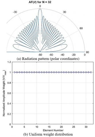
Shaping in phased array antennas refers to the ability to control the radiation pattern of the antenna by adjusting the relative phases and amplitudes of the signals in the individual antenna elements. By manipulating the relative phases and amplitudes of the signals in the different antenna elements, the radiation pattern of a phased array antenna can be shaped. By accurately adjusting the phase and amplitude of the signals sent to each element of a phased array antenna, the antenna can steer and modify its emission pattern. Here, Figure 12 demonstrates how varying the amplitude weights of the antenna elements can alter the radiation pattern.
Figure 12. Polar coordinate radiation pattern resulting from a homogenous distribution
Uniform weights
When talking about phased array antennas, the term "uniform weights" refers to the practice of feeding signals into each antenna element with the same amplitude as mentioned in literature [26]. With uniform weights, the power is distributed evenly across the antenna array since each element receives a signal of the same amplitude. To achieve a desired broad or symmetrical coverage with phased array antennas, the notion of uniform weights is frequently employed. By giving equal importance to each element in the array, the antenna generates a beam whose intensity is uniformly distributed along a single axis (the main lobe). The simplest one, every element in the array has the same weight.
$w(n)=1$ (2)
where w(n) is the weight for the nth antenna element mass.
Hanning distribution
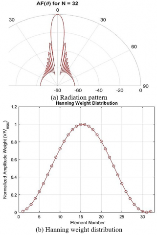
The Hanning distribution is a mathematical function used to shape or window data sequences in signal processing. It is also known as the Hanning window or the Hanning function. The Austrian meteorologist Julius von Hann is honored with this name. When doing Fourier Transform analyses on signals of finite duration, the Hanning distribution is a type of window function that can be used to minimize spectral leakage as stated in literature [27-33]. The term "spectral leakage" is used to describe the transfer of signal power into unintended frequency ranges. Figure 13(a) illustrates the predicted pattern with a pointier profile if a Hanning distribution (Figure 13(b)) is used instead of a uniform weight distribution, in which the antennas in the center of the array receive stronger signals than the antennas at the edges, in accordance with Eq. (3).
$A_n=\frac{1}{2}\left(1-\cos \left(2 \pi \frac{n}{N-1}\right)\right)$ for $n=1,2, \ldots \ldots, N$ (3)
Directivity can be improved, and power lost to the side lobes minimized by using a weight distribution based on the Hanning function in Eq. (3).
Figure 13. Polar coordinate radiation pattern generated by a Hanning weight distribution
Taylor function
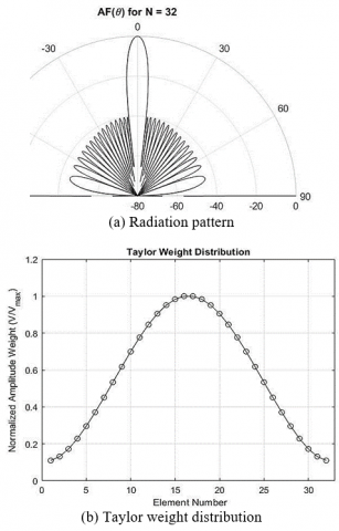
Antenna elements in a phased array can have their amplitudes tapered or weighted using a method known as the Taylor distribution. It is used to modify the array's radiation pattern such that it exhibits the desired qualities, such as reduced side lobes and a more consistent main lobe as can be seen in Eq. (4). Figure 14 shows the Radiation pattern in polar coordinates from a Taylor weight distribution.
$w(n)=(1-\alpha)+\alpha \times \cos ^2((n-N / 2) / N \times \pi)$ (4)
where,
w(n) is the weighting factor for the nth element in the array,
N is the total number of elements in the array,
α is the parameter that controls the shape of the distribution (0≤α≤1).
The form of the Taylor distribution can be altered by adjusting its value. Increasing this value will reduce the size of the main lobe and lower the side lobes, but will also increase the ripple. Conversely, a smaller value will result in a broader main lobe and taller side lobes, but with less ripple. When designing antenna arrays, especially phased array antennas, the Hanning function is another popular weighting function. Like the Taylor distribution, the Hanning function is used to modify the radiation pattern of an antenna element to achieve desired features, such as reduced side lobe levels.
Figure 14. Radiation pattern in polar coordinates from a Taylor weight distribution
3.3 Design for low-latency in communication
Multidisciplinary skills such as electrical engineering, communication theory, control theory, signal processing, and satellite technology are required to design a low latency framework for phased array antenna communication in space. Numerous parameters, like signal strength, noise, distance, bandwidth, array arrangement, antenna design, etc., affect the efficiency of such a system. Real-world designs sometimes necessitate iterative simulations and fine-tuning, and it is impossible to include all features in a single model. There are three components that make up the total latency of any given communication system:
Propagation delay: The time it takes for a signal to get from its origin to its destination is called its propagation delay. This is mostly determined by how far apart the satellite and the ground station are. We can estimate the propagation delay, D, with the following formula:
D=d/c (5)
where, d is the satellite's distance from the ground station, and c is the speed of light (3108 meters per second).
Processing delay: The time it takes for the signal to be processed at the origin, the satellite, and the receiver all contribute to the processing delay. Depending on the architecture of the system, this can change dramatically. Phased array antennas, on the other hand, have to worry about the beam forming delay. This lag time, P, can be roughly calculated with the following formula:
P=N/(f×BW) (6)
where, N is the total number of phased array elements, f is the digital beam former’s clock frequency, and BW is the signal's bandwidth.
Queuing delay: The time a signal spends in a buffer or transmission queue is known as the queuing delay. Q is a variable that changes based on the number of users and the size of the buffer. Estimating the full latency, L, goes like this:
L=D+P+Q (7)
4.1 Pattern comparison
Beamforming in phased array antennas is achieved through constructive interference between individual antenna elements. Phased array systems allow the beam's characteristics to be tailored via a variety of weighting schemes. Standard procedures include using uniform weights, the Hanning distribution, or the Taylor distribution. The signals from each antenna element have their amplitudes and/or phases distributed in this way as can be seen in Figure 15.
Figure 15. Visualizing superimposed radiation patterns of phased array antennas using uniform, Hanning, and Taylor weighting functions
Figure 16. Close-up picture of the beamwidth of phased array antennas using uniform, Hanning, and Taylor weighting functions
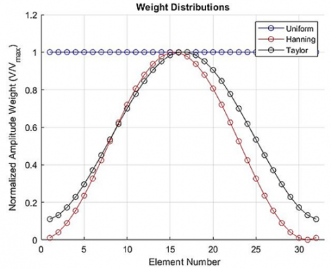
Figure 17. Superimposed weight distribution functions of phased array antennas using uniform, Hanning, and Taylor weighting functions
4.2 Beam width comparison
Beam width is an important parameter to consider when comparing the performance of various weight distributions for phased array antennas, such as uniform weights, the Hanning distribution, and the Taylor function. The main lobe's angular spread of an antenna's radiation pattern is set by the beam width. A more directed antenna with a narrower beam width. Figure 16 offers a close-up view of how the beam widths vary when using uniform, Hanning, and Taylor weighting functions. Figure 17 illustrates the corresponding weight distribution functions for each weighting scheme, showing how the weights are applied across the antenna elements to achieve the observed beam patterns.
One of SpaceX’s latest missions is to provide low-latency satellite internet worldwide. To achieve this, they have launched and continue to launch thousands of satellites into LEO (Figure 18(a)). To date, this is the first project of its size deployed with the objective of providing worldwide internet. Typically, satellites that provide internet are placed in Geosynchronous orbit, where they can service the specific region they are pointing to (Figure 18(b)), as they rotate synchronously with the earth. Compared to geosynchronous orbit, the main benefit of employing LEO is a drastic decrease in latency. Shorter signal travel times are a direct outcome of LEO satellites' proximity to Earth's surface. As a result of its low latency, it can be used for a wide range of internet purposes, including synchronous activities like chatting, playing games, and watching videos. The network's capacity is increased and quicker data transfer rates are made possible by this feature. By dynamically changing the direction of transmission beams, these systems further increase network coverage by concentrating signals on particular users or places. By lowering interference and improving signal strength, this increases the network's coverage area. Phased-array antenna systems can monitor and maintain connection with mobile devices even at high speeds, maintaining seamless connectivity, which is another way they enable mobility. Furthermore, by maximizing the use of available spectrum and avoiding the need for extra antennas and equipment, these systems have the potential to reduce infrastructure requirements. This is contribution of lower cost of installing and managing large networks. In the context of low-latency, high-speed communication networks, the ramifications of these developments pave the way for increased network performance and greater user experiences. Table 1 shows phased-array antenna systems for low-latency shaping. Table 2 shows the performance metrics of the phased array antenna distribution system for LEO communication.
Table 1. Phased-array antenna systems for low-latency shaping
|
Antenna Distribution |
Performance Metrics |
Advantages |
Disadvantages |
|
Uniform Weight |
Low-latency |
Simplicity of implementation |
Limited sidelobe suppression |
|
Beamwidth |
Symmetrical beam pattern |
Poor suppression of interference |
|
|
Sidelobe level |
Equal power distribution to all elements |
Suboptimal performance in high-density scenarios |
|
|
Hanning Distribution |
Low-latency |
Good sidelobe suppression |
Increased computational complexity |
|
Beamwidth |
Symmetrical beam pattern |
Slightly reduced main lobe gain |
|
|
Sidelobe level |
Smooth amplitude tapering at element edges |
Reduced array efficiency |
|
|
Taylor Function |
Low-latency |
Excellent sidelobe suppression |
Requires accurate knowledge of interference scenario |
|
Beamwidth |
Adjustable beam shape and control |
Increased complexity for array calibration |
|
|
Sidelobe level |
Precise sidelobe control |
Non-uniform power distribution among elements |
Table 2. Performance metrics of the phased array antenna distribution system for LEO communication
|
Antenna Distribution |
Low-Latency Performance |
Beamwidth (Degrees) |
Sidelobe Level (dB) |
|
Uniform Weight |
High |
20 |
-12 |
|
Hanning Distribution |
Medium |
18 |
-20 |
|
Taylor Function |
Very High |
22 |
-25 |
Figure 18. Comparison between LEO and geosynchronous orbit
The first problem investigated in this work is the problem associated with improving the operation of phased-array antenna systems with the purpose of increasing the performance of communication networks using LEO satellites. Thus, the importance of developing and implementing new versatile and high-performance antenna systems, is pinpointed in the context of the continuous development of new wireless technologies along with the continuously increasing need for fast and efficient internet services. From this study it has been shown that the use of phased-array antennas provides considerable benefits over that of the fixed radiation pattern antennas. Some of the important discoveries include the ability to change the pattern of radiation as this is usually achieved through the phased-array antennas, which are the types of antennas that can easily change the direction of the beams and the focus of the signals. As for the performance characteristics, the evaluation of several weighting distributions, namely Uniform, Hanning, and Taylor, revealed that Taylor distribution offers the highest performance concerning beamwidth and sidelobe level which is crucial for preserving low latency and high rate connections in LEO satellite networks. The consequences referring to the connectivity are indeed revolutionary, since the capability of adapting phased-array systems for maintaining the mobile devices connection on high velocities, and for the proactive spectrum management, can highly decrease the infrastructural costs, as well as improve the network performance and user experience. Thus, the application of phased-array antenna systems in LEO satellite networks is an evolutionary advancement for global connectivity. These programs could offer low-latency high bandwidth internet connections required in asynchronous internet activities such as online games, video and data conferencing among others. The features of the phased-array antennas also advocate for increased systems’ coverage without requiring additional base structures; this makes the growth of networks cheaper and efficient. However, based on the conclusion formulated in this study, there are several limitations that should be noted. To get the optimum performance from phased-array antennas, they need to be carefully phased, which in turn is a very technical as well as time-consuming process. Also, unequal power distribution to the antenna elements may also result in lower efficiency and performance of the total system. Atmospheric and physical barriers are some of atmospheric conditions that affect the kind of performance of phased-array systems; hence, more study is required in this particular aspect.
Future research should therefore fill the above mentioned gaps; and consider exploring other ways of improving the performance of phased-array antenna systems. Also, researchers in this domain have come up with improved methods of calibration to improve efficiency and reduce the time taken to start up the phased-array systems. Studying possibilities in enhancing the method of power distribution to the individual parts of the antenna is crucial to enhance effectiveness of the system in general. Other kinds of research that are relevant include but not limited to those on how phased-array antennas can be made to provide consistent performance under a range of environmental conditions. Furthermore, there is room for the expansion of the theoretical and practical application of various phased-array systems through their connectivity with other novel topologies for example reconfigurable intelligent surfaces and artificial intelligence. This way, future research can help improve existing as well as increase the usage of phased-array antenna systems in sophisticated communication networks.
The authors would like to thank Al-Bayan University for their support in completing this research paper.
[1] Haupt, R.L., Rahmat-Samii, Y. (2015). Antenna array developments: A perspective on the past, present and future. IEEE Antennas and Propagation Magazine, 57(1): 86-96. https://doi.org/10.1109/MAP.2015.2397154
[2] Sanguinetti, L., Björnson, E., Hoydis, J. (2019). Toward massive MIMO 2.0: Understanding spatial correlation, interference suppression, and pilot contamination. IEEE Transactions on Communications, 68(1): 232-257. https://doi.org/10.1109/TCOMM.2019.2945792
[3] Pan, C., Ren, H., Wang, K., et al. (2021). Reconfigurable intelligent surfaces for 6G systems: Principles, applications, and research directions. IEEE Communications Magazine, 59(6): 14-20. https://doi.org/10.1109/MCOM.001.2001076
[4] Saad, W., Bennis, M., Chen, M. (2019). A vision of 6G wireless systems: Applications, trends, technologies, and open research problems. IEEE Network, 34(3): 134-142. https://doi.org/10.1109/MNET.001.1900287
[5] Song, L., Di, B., Zhang, H., Han, Z. (2023). Aerial Access Networks: Integration of UAVs, HAPs, and Satellites. Cambridge University Press.
[6] Jia, Z., Sheng, M., Li, J., Niyato, D., Han, Z. (2020). LEO-satellite-assisted UAV: Joint trajectory and data collection for internet of remote things in 6G aerial access networks. IEEE Internet of Things Journal, 8(12): 9814-9826. https://doi.org/10.1109/JIOT.2020.3021255
[7] 3GPP TR 38.811. (2020). Study on New Radio (NR) to support non-terrestrial networks (Release 15). V15.4.0, 3rd Generation Partnership Project.
[8] IMT Vision–Framework and overall objectives of the future development of IMT for 2020 and beyond. Recommendation ITU, 2083-0, 2015. https://www.itu.int/dms_pubrec/itu-r/rec/m/R-REC-M.2083-0-201509-I!!PDF-E.pdf.
[9] Peterson, B., Schnaufer, D. (2018). 5G fixed wireless access array and RF front-end trade-offs. Microwave Journal E-book, pp. 10-18.
[10] Kildal, P.S., Alfonso, E., Valero-Nogueira, A., Rajo-Iglesias, E. (2008). Local metamaterial-based waveguides in gaps between parallel metal plates. IEEE Antennas and Wireless Propagation Letters, 8: 84-87. https://doi.org/10.1109/LAWP.2008.2011147
[11] Zhang, J., Björnson, E., Matthaiou, M., Ng, D.W.K., Yang, H., Love, D.J. (2020). Prospective multiple antenna technologies for beyond 5G. IEEE Journal on Selected Areas in Communications, 38(8): 1637-1660. https://doi.org/10.1109/JSAC.2020.3000826
[12] Liu, J., Shi, Y., Fadlullah, Z.M., Kato, N. (2018). Space-air-ground integrated network: A survey. IEEE Communications Surveys & Tutorials, 20(4): 2714-2741. https://doi.org/10.1109/COMST.2018.2841996
[13] Chen, S., Sun, S., Kang, S. (2020). System integration of terrestrial mobile communication and satellite communication - the trends, challenges and key technologies in B5G and 6G. China Communications, 17(12): 156-171. https://doi.org/10.23919/JCC.2020.12.011
[14] Wu, Q., Xu, J., Zeng, Y., Ng, D.W.K., Al-Dhahir, N., Schober, R., Swindlehurst, A.L. (2021). A comprehensive overview on 5G-and-beyond networks with UAVs: From communications to sensing and intelligence. IEEE Journal on Selected Areas in Communications, 39(10): 2912-2945. https://doi.org/10.1109/JSAC.2021.3088681
[15] Xiao, Z., Zhu, L., Liu, Y., Yi, P., Zhang, R., Xia, X.G., Schober, R. (2021). A survey on millimeter-wave beamforming enabled UAV communications and networking. IEEE Communications Surveys & Tutorials, 24(1): 557-610. https://doi.org/10.1109/COMST.2021.3124512
[16] Peng, D., Bandi, A., Li, Y., Chatzinotas, S., Ottersten, B. (2021). Hybrid beamforming, user scheduling, and resource allocation for integrated terrestrial-satellite communication. IEEE Transactions on Vehicular Technology, 70(9): 8868-8882. https://doi.org/10.1109/TVT.2021.3097149
[17] Ahmed, I., Khammari, H., Shahid, A., Musa, A., Kim, K.S., De Poorter, E., Moerman, I. (2018). A survey on hybrid beamforming techniques in 5G: Architecture and system model perspectives. IEEE Communications Surveys & Tutorials, 20(4): 3060-3097. https://doi.org/10.1109/COMST.2018.2843719
[18] Ma, Y., Yang, S., Chen, Y., Qu, S.W., Hu, J. (2019). Pattern synthesis of 4-D irregular antenna arrays based on maximum-entropy model. IEEE Transactions on Antennas and Propagation, 67(5): 3048-3057. https://doi.org/10.1109/TAP.2019.2896730
[19] Wu, Q., Zhang, R. (2019). Towards smart and reconfigurable environment: Intelligent reflecting surface aided wireless network. IEEE Communications Magazine, 58(1): 106-112. https://doi.org/10.1109/MCOM.001.1900107
[20] Wei, Z., Zhao, L., Guo, J., Ng, D.W.K., Yuan, J. (2018). Multi-beam NOMA for hybrid mmWave systems. IEEE Transactions on Communications, 67(2): 1705-1719. https://doi.org/10.1109/TCOMM.2018.2879930
[21] Li, J., Jing, X., Zhang, Y., Mu, J. (2019). Performance analysis of agile-beam NOMA in millimeter wave networks. IEEE Access, 8: 6638-6649. https://doi.org/10.1109/ACCESS.2019.2958337
[22] Herd, J.S., Conway, M.D. (2015). The evolution to modern phased array architectures. Proceedings of the IEEE, 104(3): 519-529. https://doi.org/10.1109/JPROC.2015.2494879
[23] Dolph, C.L. (1946). A current distribution for broadside arrays which optimizes the relationship between beam width and side-lobe level. Proceedings of the IRE, 34(6): 335-348. https://doi.org/10.1109/JRPROC.1946.225956
[24] Al Barazanchi, I.I., Hashim, W., Thabit, R., Sekhar, R., Shah, P., Penubadi, H.R. (2024). Secure Trust Node Acquisition and Access Control for Privacy-Preserving Expertise Trust in WBAN Networks. In: Rasheed, J., Abu-Mahfouz, A.M., Fahim, M. (eds). Forthcoming Networks and Sustainability in the AIoT Era. FoNeS-AIoT 2024. Lecture Notes in Networks and Systems, vol. 1036. Springer, Cham. https://doi.org/10.1007/978-3-031-62881-8_22
[25] Valdes-Garcia, A., Nicolson, S., Lai, J.W., et al. (2010). A SiGe BiCMOS 16-element phased-array transmitter for 60GHz communications. In 2010 IEEE International Solid-State Circuits Conference - (ISSCC), San Francisco, CA, USA, pp. 218-219. https://doi.org/10.1109/ISSCC.2010.5433956
[26] Reynolds, S.K., Natarajan, A.S., Tsai, M.D., et al. (2010). A 16-element phased-array receiver IC for 60-GHz communications in SiGe BiCMOS. In 2010 IEEE Radio Frequency Integrated Circuits Symposium, Anaheim, CA, USA, pp. 461-464. https://doi.org/10.1109/RFIC.2010.5477306
[27] Reynolds, S.K., Floyd, B.A., Pfeiffer, U.R., et al. (2006). A silicon 60-GHz receiver and transmitter chipset for broadband communications. IEEE Journal of Solid-State Circuits, 41(12): 2820-2831. https://doi.org/10.1109/JSSC.2006.884820
[28] Cohen, E., Jakobson, C., Ravid, S., Ritter, D. (2010). A bidirectional TX/RX four-element phased array at 60 GHz with RF-IF conversion block in 90-nm CMOS process. IEEE Transactions on Microwave Theory and Techniques, 58(5): 1438-1446. https://doi.org/10.1109/TMTT.2010.2042902
[29] Ogunleye, G.O., Akinsanya, S.E. (2022). Elliptic curve cryptography performance evaluation for securing multi-factor systems in a cloud computing environment. Iraqi Journal of Science, 63(7): 3212-3224. https://doi.org/10.24996/ijs.2022.63.7.40
[30] Khodher, M.A.A., Alabaichi, A., Altameemi, A.A. (2022). Steganography encryption secret message in video raster using DNA and chaotic map. Iraqi Journal of Science, 63(12): 5534-5548. https://doi.org/10.24996/ijs.2022.63.12.38
[31] Jawad, R.N. (2022). Proposed hybrid technique in cryptanalysis of cryptosystem based on PSO and SA. Iraqi Journal of Science, 63(10): 4547-4558. https://doi.org/10.24996/ijs.2022.63.10.37
[32] Jabbar, M.S., Al_Barazanchi, I.I., Khalaf, A.L., JosephNg, P.S., Radhi, A.D. (2023). Optimizing multi-antenna M-MIMO DM communication systems with advanced linearization techniques for RF front-end nonlinearity compensation in a comprehensive design and performance evaluation study. Periodicals of Engineering and Natural Sciences, 11(3): 124-138. http://doi.org/10.21533/pen.v11i3.3609
[33] Niu, Y., Al Sayed, I.A., Alya'a, R.A., Al_Barazanchi, I., JosephNg, P.S., Jaaz, Z.A., Gheni, H.M. (2023). Research on fault adaptive fault tolerant control of distributed wind solar hybrid generator. Bulletin of Electrical Engineering and Informatics, 12(2): 1029-1040. https://doi.org/10.11591/eei.v12i2.4242