Susilo Hariyanto*![]() | Yusephus Decupertino Sumanto
| Yusephus Decupertino Sumanto![]() | Bibit Waluyo Aji
| Bibit Waluyo Aji![]() | Nastangini
| Nastangini![]() | Sri Nur Chasanah
| Sri Nur Chasanah![]() | Aisyah Andria Rahman Raharjo
| Aisyah Andria Rahman Raharjo![]()
© 2024 The authors. This article is published by IIETA and is licensed under the CC BY 4.0 license (http://creativecommons.org/licenses/by/4.0/).
OPEN ACCESS
Termites have a unique heat regulation where termite nests can maintain a stable temperature even though the temperature outside the nest changes. The termite nest itself has a porous structure that causes the temperature to move with a certain mechanism. The temperature in termite nests is considered to move through two phases, namely the conduction phase and the convection phase. The purpose of this research is to build a thermal insulation model and numerical analysis of thermal insulation models. The thermal insulation model in termite nests is made with a porous media approach. Furthermore, finite element methods are used for simulation and numerical analysis of thermal insulation models in termite nests. Finite element method with Galerkin for element discretization and Runge-Kutta for time discretization. The finite element method simulates thermal distribution in termite nests. The thermal insulation model was validated with original data using MAPE and R2 Score. The validation results obtained the MAPE score is 3% for the conduction phase and 0.2% for the convection phase. Changes in parameters have a significant effect on conduction but not convection.
thermal insulation, heat transfer, termite nest structure, finite element method
Macrotermes sp. termites are one of the termite species found in Indonesia. With their tendency to build nests in the soil, including the species Macrotermes gilvus, they are known for being quite active in constructing their nests, often comprising complex structures with sufficiently wide air passages within [1]
The composition of Macrotermes sp. termite nests, consisting of a mixture of soil, saliva, and other organic materials, is known to maintain a stable temperature even as the temperature outside fluctuates [2]. This makes the termite nest characteristic applicable to buildings in Indonesia. One common application is the use of environmentally friendly building techniques inspired by the structure of termite nests. For example, environmentally friendly construction concepts that utilize a mixture of natural and recycled materials, as well as building designs that consider natural air circulation, can reflect the principles found in the structure of Macrotermes sp. termite nests [3]. By applying these principles, it is hoped that buildings in Indonesia can become more energy-efficient and environmentally friendly, while benefiting from the uniqueness and sustainability of the local environment.
Thermal insulation is an essential aspect of constructing buildings that can affect their energy efficiency and comfort levels. Termite nests serve as a great inspiration for thermal insulation structures due to their shaft structures that maintain a stable temperature inside the building, both during the day and night [2]. However, further research is required to optimize the use of the termite nest model for thermal insulation in buildings [4].
Porous media is a commonly occurring structure in nature that consists of solid objects with many empty spaces. The Diffusion Equation is not only limited to fluid flow but also heat transfer. It is used for modeling fluid flow in porous media [5]. The heat transfer mechanism is of particular interest in porous media, and termite nests serve as the primary inspiration for this heat flow model. According to research from Harvard, the primary heat flow process in termite nests is convection, which maintains temperature stability. The heat transfer model is a partial differential equation [4]. Partial differential equations can be solved in two ways: analytical solutions and numerical solutions. Numerical solutions are widely discussed through various methods, such as the Finite Element Method, Finite Difference Method, and Finite Volume Method [6-8]. The finite element method is widely used in solving solutions of hot equations [9-11].
The thermal behavior of termite nests cannot be accurately predicted with traditional approaches such as thermal conduction models. Therefore, further research is needed to develop mathematical models that can predict the thermal behavior of termite nests. A study by Lu et al. [12] in 2024 has developed a porous media-based mathematical model to simulate fluid flow and heat transfer.
The integration of energy conservation concepts and fluid flow equations through porous media in porous media mathematical models will provide precise and accurate solutions for modeling the thermal behavior of termite nests as thermal insulation. A study from Feng et al. [13] has demonstrated that porous media mathematical models can provide more accurate results in predicting the thermal behavior of porous insulation materials compared to thermal conduction models.
Research on the development of thermal insulation models in termite nests using a porous media mathematical approach needs to be conducted. This will help us understand how heat is transferred in such structures. The model is expected to provide significant benefits for the development of thermal insulation technology in buildings. This will result in buildings that are more efficient and environmentally friendly. Recent research published in the journal Science Advances revealed that termite nests consist of many interconnected microscopic pores [14]. These pores enable termite nests to regulate thermal, humidity, and internal carbon dioxide gas concentrations. This allows termites to move around without any interference. Essentially, termites work like lungs, inhaling and exhaling air automatically. The microscopic structure of building walls can optimize thermoregulation and ventilation. This latest finding could also lead to the development of building designs that have thermal regulation systems and automatic air circulation.
Darcy's Law is the basic law of fluid motion in porous media Darcy's Law defines the flow rate of water through a porous medium, assuming laminar flow. By combining the concepts of permeability and pressure in determining the flow rate of fluid, the Darcy equation is obtained as follows [15, 16]:
$Q=-k A \frac{\Delta h}{L}$
where, Q=flow discharge (m3/s); A=the area of the cross-sectional area passed by the fluid (m2); k=hydraulic conductivity (m/s); L=the length of cross-sectional distance (m); $\Delta h=h_{\text {in }}-h_{\text {out }}$ changes in water level or hydraulic head (m).
A negative sign indicates that the flow is a combination of increasing gradients, in other words the flow will occur from the high end to the low end.
Darcy's Law defines permeability as the measure of a porous material's ability to allow fluid to flow through it. In other words, the rate of flow of a homogeneous fluid through a porous material is directly proportional to the pressure gradient and the normal direction to the cross-sectional area of the flow direction and inversely proportional to viscosity. The value of permeability depends on the size of the pores and their distribution within the porous material [3, 17, 18].
The part of the pore space that is filled with fluid is referred to as fluid saturation or fluid saturation. Saturation is defined as the ratio between the pore volume of a porous medium occupied by a particular fluid and the total pore volume of a porous medium [14].
$S=\frac{V_f}{V_t}$
where, $S=$ Saturation; $V_f=$ Pore volume containing fluid; $V_t=$ Total interconnected pore volume.
By S is saturation, Vf the volume of the pore containing the fluid, and Vt the total volume of the corresponding pore. The mechanism of fluid movement in a porous medium is determined by fluid transport. The diffuse fluid in porous media is caused by dispersion. In practice, dispersions are used in the fluid flowing state. A measure of the ability of a porous medium to spread fluid in different directions is called the dispersion coefficient [19].
$J=-D\left(\frac{d C}{d x}\right)$
J is the fluid transfer rate, D is the disperse coefficient, $\left(\frac{d C}{d x}\right)$ is the concentration gradient, and-means the direction of diffusion follows the direction of the concentration gradient.
The amount of fluid mass in a porous medium will forever remain unchanged. This is following the law of conservation of mass which states that mass can change its shape, but cannot be made or destroyed. This makes fluid movement in porous media easy to predict for a certain time [20].
The numerical method is a solution technique that is formulated mathematically utilizing calculation/arithmetic operations and is done repeatedly with the help of a computer or manually. The Finite Element Method is a numerical method used to solve problems of a continuous system, where in solving the problem, the system was first idealized as an arrangement of discrete elements that make up the distribution of a voltage and displacement. So that the complete solution is produced from the combination of stress and displacement distributions that meet the equation of equilibrium of force and suitability of displacement at the connection of each element. Finite element methods are used in finding numerical solutions of partial differential equations, as in porous media. Based on the laws used, the exact research parameters to obtain mathematical modeling use parameters such as permeability, porosity, compressibility, viscosity, and thermal conductivity of termite nest objects.
2.1 Data
The research utilizes heat transfer information obtained through observations. The observations were carried out on a termite mound belonging to Captotermes curviganathus. Data collection took place in Boyolali regency, Indonesia, between September 11th and 26th, 2023. A total of 11 data points for location and 24 data points for time were gathered for this study.
2.2 Methods
Data is collected with thermocouple in from outside termite nest into inside termite nest. The obtained data is then used for determining the boundary conditions of the equation. Determination of the boundary conditions employs polynomial interpolation. The obtained data is used for validating parameters.
In termite nests, thermals propagate into the nest by going through the soil first. Thermals propagate on the ground which is the solid part, so that thermals propagate conductively. In this section thermal insulation occurs. After going through the conduction phase, thermals propagate on termite nests which are part of the void. Thermal propagation occurs by convection in termite nests as shown in Figure 1.
Figure 1. Termite nest structure
In this phase, the thermals are no longer isolated so that the temperature in the termite nest tends to be stable. This shows if the thermal transfer in termite nests is multiphase, namely from the conduction phase to the convection phase. In this research, we limit mathematical modeling into only 1-dimensional conditions, where heat flows through the soil surface in the porous media of termite nests.
The isolation model is constructed by several laws of physics, the conduction model is built. The law of conservation of energy and the law of Fourier. In the conduction phase, thermal uses Fourier's law because there are conduction variables. Fourier's law can be used to explain how thermal is transferred among the parts of a termite nest. This allows the termite nest to maintain a suitable temperature for their activities inside the nest. First of all, we use the law of energy conversation to illustrate heat transfer.
The Law of Energy Conservation is as follows:
$Q=m c d u=A d x \rho c d u$ (1)
Heat changes with time, so that the thermal and heat parts change into derivatives of time as follows:
$\frac{Q}{d t}=A d x \rho c \frac{d u}{d t}$ (2)
Fourier's law is formulated as follows:
$Q=-\lambda A \frac{d u}{d t}$ (3)
The total heat of a system is a combination of exhaustive heat and incoming heat.
$\begin{gathered}Q=Q_{\text {out }}-Q_{\text {in }}=d Q \\ Q=-d Q=A d x \rho c \frac{d u}{d t}\end{gathered}$ (4)
Press (3) is substituted in the section of Eq. (4) so that the following equation is obtained:
$Q \frac{d u}{d t}=-\frac{1}{A \rho c} \frac{d Q}{d x}=-\frac{1}{A \rho c} \frac{d\left(-\lambda A \frac{d u}{d x}\right)}{d x}=-\frac{-\lambda A}{A \rho c} \frac{d\left(\frac{d u}{d x}\right)}{d x}$ (5)
The heat conduction equation in porous media is as follows:
$\frac{d u}{d t}=-\frac{1}{A \rho c} \frac{d^2 u}{d x^2}$ (6)
The equation is then written in derived form as follows:
$\rho c \frac{\partial u}{\partial t}=k \nabla(\nabla u)$ (7)
E is energy, $m$ is mass, c is specific thermal capacity, u is thermal, ρ is density, μ is viscosity, A is cross-sectional area, and u is discharge.
Convection constructed with Darcy's Law and Continuity Equation, Darcy's Law in press (1), can be rewritten as u.
$\boldsymbol{u}=-\frac{k}{\mu}(\nabla P+\rho g)$ (8a)
$\frac{\partial}{\partial t}(\rho \varphi)+\nabla(\rho \boldsymbol{u})=Q_m$ (8b)
In the above equation, $\rho$ is the density of the fluid, $\varphi$ is porosity, and $Q_m$ is the source of mass. Substitution of the equation of Darcy's Law by velocity in the continuity equation yields:
$\frac{\partial}{\partial t}(\rho \varphi)+\nabla \cdot \rho\left[-\frac{k}{\mu}(\nabla P+\rho \boldsymbol{g})\right]=Q_m$ (9)
$\frac{\partial}{\partial t}(\rho \varphi)=\varphi \frac{\partial}{\partial t} \rho+\rho \frac{\partial}{\partial t} \varphi=\varphi \frac{\partial \rho}{\partial P} \frac{\partial P}{\partial t}+\rho \frac{\partial \varphi}{\partial P} \frac{\partial P}{\partial t}$ (10)
$\varphi \frac{\partial \rho}{\partial P} \frac{\partial P}{\partial t}+\rho \frac{\partial \varphi}{\partial P} \frac{\partial P}{\partial t}=\varphi \rho c_f \frac{\partial P}{\partial t}+\rho \varphi c_r \frac{\partial P}{\partial t}=\rho \varphi c_t \frac{\partial P}{\partial t}$ (11)
In the above equation, $c_f$ and $c_r$ are the compressibility of the fluid and the compressibility of the rock, respectively. $c_t$ refers to total compressibility. Substitute Eq. (11) becomes Eq. (9):
$\rho \varphi c_t \frac{\partial P}{\partial t}++\nabla \cdot \rho\left[-\frac{k}{\mu}(\nabla P+\rho \boldsymbol{g})\right]=Q_m$
In the equation above, $k_0$ is the initial permeability and $\varphi_0$ is the initial porosity.
According to Gay-Lussac's law:
$\frac{P}{u}=r$
where, $u$ is thermal, $r$ is a constant, or it can also be written $P \propto T$.
$P=r u$
So the heat equation in a porous medium is:
$\varphi_0 c_t \rho \frac{\partial(u r)}{\partial t}+\frac{k_0}{\mu} \frac{\partial}{\partial x}\left[-\rho \frac{\partial(r u)}{\partial x}\right]=Q_m$ (12)
where, $T(x, t)$ is the heat of the solution while $r$ is the ratio of pressure and thermal (constant).
$\begin{gathered}\varphi_0 c_t \rho r \frac{\partial u}{\partial t}+\frac{k_0}{\mu} \frac{\partial}{\partial x}\left[\rho r \frac{\partial u}{\partial x}\right]=Q_m \\ \varphi_0 c_t \rho r \frac{\partial u}{\partial t}+\frac{k_0}{\mu} \frac{\partial}{\partial x}\left[-\rho r \frac{\partial u}{\partial x}\right]=Q_m\end{gathered}$
So that the equation of 1-dimensional heat convection in porous media is:
$\varphi_0 c_t \rho r \frac{\partial u}{\partial t}-\frac{k_0}{\mu} \rho r \frac{\partial}{\partial x}\left(\frac{\partial u}{\partial x}\right)=Q_m$ (13)
Or in general it can be written as:
$\operatorname{\rho r} \varphi c_t \frac{\partial u}{\partial t}-\frac{k_0}{\mu} \rho r \nabla \cdot(\nabla u)=Q_m$
In the conduction phase using boundary conditions with boundary conditions, then the convection part of the boundary conditions is:
$\begin{aligned} u(0, t) & =26.28-6.72 \sin \left(\frac{\pi t}{12}\right), u(1, t) \\ & =26.2596+0.2541 \sin \left(\frac{\pi t}{24}\right) u(x, 0) \\ & =-0.0746 x^2+0.6782 x+25.09 u(0, t) \\ & =26+0.3233 t^{0.2764}, u(1, t) \\ & =-0.0024 t^2+0.0858 t \\ & +0.0504, u(x, 0) \\ & =0.16 x^2+0.67 x+25.4\end{aligned}$
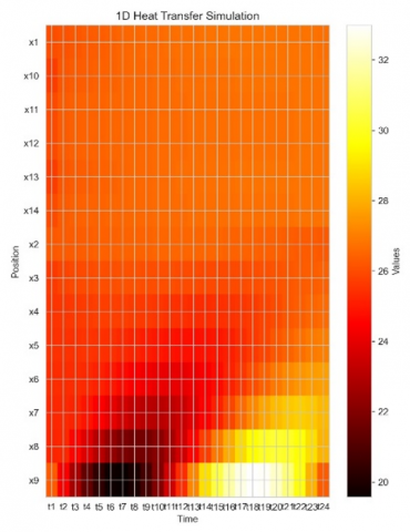
The system employs 11 element partitions in the x position section, employing a linear partitioning approach. Time discretization utilizes the Runge-Kutta method with a 1-hour time unit for single day. The simulation results are as follows.
Point 0 is the time that shows t=6 (06:00). The simulation shows the highest thermal of termite nests at 32℃, the lowest thermal at 20℃, and thermal stable at 26℃. The solution produces a multiphase heat equation, that is, phase conduction and convection phase. The thermal is isolated in the conduction phase to a position x<35cm. Therefore, the thermal is stable in the convection phase when x>35cm. In phase convection, its thermal conductivity is minimal, hindering the propagation of heat. As a result, the thermal is always stable at 26℃.
Next, a thermal comparison between the simulation outcomes and real data is conducted (Figure 2). We depict 24 time points per hour derived from measurements over the course of a single day.
Based on Figure 3, it is evident that the real data closely aligns with the simulation results, indicating the predictive capability of the simulation data. During the conduction phase, thermal levels exhibit an ascent at t=1 (01:00) and t=19 (19:00), while experiencing a decline at t=7 (07:00) and t=13 (13:00). In contrast, during the convection phase, thermals maintain a consistent movement throughout each time unit. This observation suggests that during the conduction phase, thermal insulation is maximized, resulting in the cessation of heat propagation during the convection phase.
After obtaining a thermal insulation model, a model evaluation was carried out using MAPE and R2 Score.
Figure 2. Thermal simulation
(a) t=1
(b) t=2
(c) t=3
(d) t=4
(e) t=5
(f) t=6
(g) t=7
(h) t=8
(i) t=9
(j) t=10
(k) t=11
(l) t=12
(m) t=13
(n) t=14
(o) t=15
(p) t=16
(q) t=17
(r) t=18
(s) t=19
(t) t=20
(u) t=21
(v) t=22
(w) t=23
(x) t=24
Figure 3. Comparison of simulation results and real data
(a) t=1
(b) t=2
(c) t=3
(d) t=4
Figure 4. Temperature distribution
Table 1. Evaluation score
|
No. |
Phase |
MAPE |
R2 Score |
|
1 |
Conduction Phase |
0.0349 |
0.742 |
|
2 |
Convection Phase |
0.0023 |
0.85 |
From the Table 1 obtained the value of MAPE in the conduction phase of 3% with its R2 Score is 0.74. In the convection phase, the MAPE value is 0.2% and its R2 Score is 0.85. Based on MAPE criteria and research methods, the results of model evaluation show good preparation. This is evidenced by the MAPE <20% and 0.7≤R2 Score<0.9.
Errors obtained in model evaluation are required to validate the model. Good isolation model is indicated by a small error value. Furthermore, such models can be used for prediction and analysis of thermal distributions. In the model there are parameters that affect it. Therefore, parameter analysis is needed to see the distribution of the model.
The parameter k in this conduction section is k1=kρc. Four parameter schemes were used in this study are, k1=1, k2=0.494, k3=0.0055, and k4=0.00275. Optimal k is a parameter obtained from field data. In the conduction phase, a given k shows the resulting thermal difference at each point (position). This means that parameters affect the conduction phase. While in the convection phase, the thermal remains stable at every point (position). This shows that the parameter has no effect on the convection phase.
The following thermal patterns in the parameter analysis during the conduction phase.
From Figure 4, the given k values result in different positions. The parameters k4 are isolated at point (position) 10cm, k3 is isolated at point 1cm, k is optimal at point 20cm, k2 and k1 are squeezed at point 35cm. So, the position length at k4<k3<k is optimal <k1. This shows that the smaller the k value, the closer it is to 0 and the smaller the length (Figure 5).
In the convection phase there are combined parameters of $\frac{k}{\mu \varphi c_t}$. When these parameters are raised to the maximum or lowered to an infinite minimum, the thermal remains stable.
In the Figure 4, 12 parameters k are given in the convection phase. The value $0.17 \leq k \leq 1.00$, obtained thermally that is always stable. Experiments when given k close to 0, i.e. k1 and k2, show unstable thermals. This can be affected by its thermal conductivity. Thus, broadly speaking, the given parameters k does not have a significant influence on the convection phase. As a result, the thermals are always stable.
Based on Figure 4, the thermal will be more quickly isolated in the conduction section if the parameter is smaller, in the graph of the parameter value below 0.011, it is quite difficult to find a material with that much thermal conductivity, so it can be modified by reducing the density or compressibility of the material. Materials with a conductivity of 0.011 can maintain thermal by carrying out heat storage. The thermal will be isolated more slowly if the total parameter is close to 1 or reaches the limit of the insulator material, because the thermal has been isolated in the conduction section, the size of the volume in the convection section is also affected in thermal stability.
Figure 5. Temperature isolation position
In termite nests, there is a change in heat propagation from conduction to convection, so that heat undergoes 2 phases in heat propagation. In the conduction phase, the thermal magnitude is still influenced by parameters in the termite nest. While in the convection phase, the thermal is always stable and not too influenced by any parameters. Based on the results of this research, it can be understood how changes in parameters affect thermal distribution. Permeability, porosity, compressibility, viscosity, and thermal conductivity can serve as a basis for the construction of building compositions with natural thermal insulation. The conducted simulation demonstrates that the constructed model adeptly captures the heat distribution within termite nests during both the Conduction and Convection Phases, achieving an MAPE (Mean Absolute Percentage Error) of 0.0349 with an R2 Score of 0.742 for the Conduction Phase, and an MAPE of 0.0023 with an R2 Score of 0.85 for the Convection Phase.
The work was funded by the Directorate of Learning and Student Affairs, Directorate General of Higher Education, Research, and Technology-Kemdikbudristek through the Student Creativity Program (PKM) and Universitas Diponegoro (Grant No.: 2383/E2/DT.01.00/2023).
|
$Q$ |
Flow discharge (m3/s) |
|
$A$ |
The area of the cross-sectional area passed by the fluid (m2) |
|
$K$ |
Hydraulic conductivity (m/s) |
|
$L$ |
The length of cross-sectional distance (m) |
|
$\Delta h$ |
Changes in water level or hydraulic head (m) |
|
$S$ |
Saturation |
|
$V_f$ |
Pore volume containing fluid |
|
$V_t$ |
Total interconnected pore volume |
|
$J$ |
The fluid transfer rate |
|
$m$ |
Mass (kg) |
|
$c$ |
Specific thermal capacity |
|
$u$ |
Temperature |
|
$x$ |
Position |
|
$\rho$ |
Density |
|
$k_0$ |
Porosity |
|
$\varphi$ |
Permeability |
|
$k$ |
Conductivity |
|
$E$ |
Energy |
|
$\mu$ |
Viscosity |
|
$u$ |
Discharge |
|
$\nabla P$ |
Pressure |
|
$g$ |
Gravitation |
|
$\varphi$ |
Porosity |
|
$Q_m$ |
Source of mass |
[1] Ratiknyo, H., Ahmad, I., Budiyanto, B.H. (2018). Diversity and abundance of termites along altitudinal gradient and slopes in Mount Slamet, Central Java, Indonesia. Biodiversitas Journal of Biological Diversity, 19(5): 1649-1658. https://doi.org/10.13057/biodiv/d190508
[2] Kusumawardhani, D., Nandika, D., Karlinasari, L., Arinana, A., Batubara, I. (2021). Architectural and physical properties of fungus comb from subterranean termite Macrotermes gilvus (Isoptera: Termitidae) mound. Biodiversitas Journal of Biological Diversity, 22(4). https://doi.org/10.13057/biodiv/d220406
[3] Sumardi, S., Basyuni, M., Wati, R. (2018). Antimicrobial activity of polyisoprenoids of sixteen mangrove species from North Sumatra, Indonesia. Biodiversitas Journal of Biological Diversity, 19(4): 1243-1248. https://doi.org/10.13057/biodiv/d190409
[4] King, H., Ocko, S., Mahadevan, L. (2015). Termite mounds harness diurnal temperature oscillations for ventilation. Proceedings of the National Academy of Sciences, 112(37): 11589-11593. https://doi.org/10.1073/pnas.1423242112
[5] Nabizadeh, A., Abbasi, M., Siavashi, J., Sharifi, M., Movaghar, M.R.K. (2022). Fluid flow modeling through pressure-dependent porous media: An analytical solution and a computational fluid dynamics approach. Groundwater for Sustainable Development, 18: 100776. https://doi.org/10.1016/j.gsd.2022.100776
[6] Steinbacher, L.M., Ait-Alla, A., Rippel, D., Düe, T., Freitag, M. (2022). Modelling framework for reinforcement learning based scheduling applications. IFAC-PapersOnLine, 55(10): 67-72. https://doi.org/10.1016/j.ifacol.2022.09.369
[7] Xiong, Z., Wang, X., He, M., Benabou, L., Feng, Z. (2022). Investigation on thermal conductivity of silver-based porous materials by finite difference method. Materials Today Communications, 33: 104897. https://doi.org/10.1016/j.mtcomm.2022.104897
[8] Li, W., Yu, B., Wang, X., Wang, P., Sun, S. (2012). A finite volume method for cylindrical heat conduction problems based on local analytical solution. International Journal of Heat and Mass Transfer, 55(21-22): 5570-5582. https://doi.org/10.1016/j.ijheatmasstransfer.2012.05.043
[9] Bilal, S., Mahmood, R., Majeed, A.H., Khan, I., Nisar, K.S. (2020). Finite element method visualization about heat transfer analysis of Newtonian material in triangular cavity with square cylinder. Journal of Materials Research and Technology, 9(3): 4904-4918. https://doi.org/10.1016/j.jmrt.2020.03.010
[10] He, M., Yang, Q., Li, N., Feng, X., Liu, N. (2021). An extended finite element method for heat transfer with phase change in frozen soil. Soil Mechanics and Foundation Engineering, 57: 497-505. https://doi.org/10.1007/s11204-021-09698-z
[11] Abidin, M.N.Z., Misro, M.Y. (2022). Numerical simulation of heat transfer using finite element method. Journal of Advanced Research in Fluid Mechanics and Thermal Sciences, 92(2): 104-115. https://doi.org/10.37934/arfmts.92.2.104115
[12] Lu, X.K., Zhao, Y.Y., Zhang, Y., Wu, M. (2024). Numerical study on fluid flow behavior and heat transfer performance of porous media manufactured by a space holder method. Materials, 17(11): 2695. https://doi.org/10.3390/ma17112695
[13] Feng, X.B., Liu, Q., He, Y.L. (2020). Numerical simulations of convection heat transfer in porous media using a cascaded lattice Boltzmann method. International Journal of Heat and Mass Transfer, 151: 119410. https://doi.org/10.1016/j.ijheatmasstransfer.2020.119410
[14] Singh, K., Muljadi, B.P., Raeini, A.Q., Jost, C., Vandeginste, V., Blunt, M.J., Theraulaz, G., Degond, P. (2019). The architectural design of smart ventilation and drainage systems in termite nests. Science Advances, 5(3): eaat8520. https://doi.org/10.1126/sciadv.aat8520
[15] Satiawati, L., Yulia, P.S. (2019). Penurunan persamaan darcy dari persamaan navier-stokes untuk reservoir aliran linier dan radial. Petro: Jurnal Ilmiah Teknik Perminyakan, 8(2): 65-69. https://doi.org/10.25105/petro.v8i2.4778
[16] Shen, Z.W. (2022). Darcy’s law for porous media with multiple microstructures. arXiv:2211.16303. https://doi.org/10.48550/ARXIV.2211.16303
[17] Ramdhan, A.M., Arifin, A., Hermawan, E., Hutasoit, L.M. (2021). Analisis pengaruh nilai konduktivitas hidraulik dan dispersivitas dinamik terhadap remediasi air tanah menggunakan simulasi numerik. Jurnal Teknik Hidraulik, 12(2): 107-118. https://doi.org/10.32679/jth.v12i2.658
[18] Galvis, L.C., Ruge Cárdenas, J.C., Galvis-Salamanca, L.C., Pulgarín Morales, L., Bastidas, J.G., Olarte Garzón, M.C. (2021). Permeability measurement in porous media under unsaturated paths. DYNA, 88(219): 123-130. https://doi.org/10.15446/dyna.v88n219.95162
[19] Madie, C.Y., Togue, F.K., Woafo, P. (2022). Dispersion of pollutants in a porous medium with finite thickness and variable dispersion coefficients. Heliyon, 8(8): e10083. https://doi.org/10.1016/j.heliyon.2022.e10083
[20] Junaidin, B., Cahyono, M.A. (2019). Conceptual design of electrical ducted fan (EDF). In Conference SENATIK STT Adisutjipto Yogyakarta, Buyung Junaidin, 5: 3-8. https://doi.org/10.28989/senatik.v5i0.311