Ahmad Jundi*![]() | Yaser Alaiwi
| Yaser Alaiwi![]()
© 2024 The authors. This article is published by IIETA and is licensed under the CC BY 4.0 license (http://creativecommons.org/licenses/by/4.0/).
OPEN ACCESS
This study focuses on the design and analysis of a compound die, essential in sheet metal processing. A product from the market, defined by specific dimensions, is selected for a detailed representation in SOLIDWORKS. The design of the die, guided by mathematical modeling, aims to optimize the thickness of each component, considering the impact of cutting forces. Executed in SOLIDWORKS, the design is then subjected to a comprehensive structural analysis using ANSYS Workbench. This phase evaluates stress levels, deformations, and safety factors. A critical element of this research is the comparison between AISI D2 and AISI O1 tool steels, assessing their effectiveness in die construction. Specifically, the analysis focuses on the Piercing Punch and Blanking Punch within the die, examining their performance under operational conditions.
sheet metal, compound die, finite element method, product
Sheet metal is a key material in industrial manufacturing due to its wide range of applications. It's used in everything from basic building structures to complex parts like airplane components. This paper explores the various types of sheet metal, each with unique properties making them suitable for different industrial uses. These metals are typically iron based, mixed with elements like copper or chromium, to meet specific industry needs. For example, stainless steel is often used where rust resistance is crucial, and aluminum is preferred for its lightweight in applications were reducing weight matters. In the automotive industry, sheet metal is crucial for making car bodies and frames, showcasing its versatility. Its use extends to construction, where it serves both functional and decorative purposes. Sheet metal's flexibility is also evident in the production of household appliances and electronics. In the medical field, it's important for making tools that are safe and easy to clean [1].
Employing compound die technology in the design and fabrication phases directly tackles prevalent issues in sheet metal processing. By facilitating multiple cutting actions like piercing, blanking, and drawing within a single station and press cycle, compound dies streamline production, markedly diminishing the time and expense linked to manufacturing intricate components. The capability to fabricate an L-shaped object with three perforations in one cycle illustrates the system's operational efficiency and precision. This efficiency not only showcases a significant advancement in mechanical accuracy but also aligns with the industrial demand for more effective, cost-efficient, and high-quality production methods. For instance, the ability to produce an L-shaped product with three holes in one press cycle exemplifies the efficiency and precision that compound dies bring to metal fabrication. This not only demonstrates a substantial leap in mechanical accuracy but also highlights the method's effectiveness in tackling the intricate demands of sheet metal processing. Such a technique minimizes material waste and optimizes production time, directly addressing the industry's call for more efficient, cost-effective, and high-quality manufacturing solutions.
Despite advancements in sheet metal processing, manufacturing complex parts, such as those involving multiple cuts and features, presents specific challenges. This research showcases an advanced compound die technology for efficiently producing a component have L shape with three holes, a design that demands precise execution, especially considering its complexity and the precision required for each of the four cuts.
Facing these challenges head-on, this study seeks to fill the knowledge gap in employing cutting techniques for intricate designs, aiming to enhance the efficiency and precision of sheet metal processing. By investigating the best practices for utilizing compound dies in such applications, this research contributes innovative solutions that respond to the industrial need for more efficient, cost-effective, and high-quality manufacturing methods.
This research aims to significantly enhance sheet metal processing through the advanced use of compound die technology, an essential tool for executing multiple operations with high efficiency and precision. The study focuses on the design aspects of compound dies, emphasizing the importance of accurate design to meet the rigorous demands of metal fabrication. It critically examines the impact of AISI D2 and AISI O1 tool steels on die performance and durability, providing key insights for improving sheet metal fabrication techniques. This investigation is crucial for developing more efficient and innovative manufacturing methods.
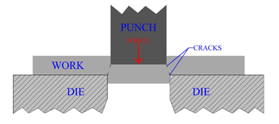
Figure 1 below shows the metal-forming process in general.
Figure 1. Sheet metal forming using simple die [1]
Recent advancements in the field of compound die design have demonstrated significant improvements in both efficiency and cost-effectiveness. A notable study successfully integrated compound and progressive dies within a single framework for the fabrication of U-shaped components, resulting in marked improvements in both the quality and efficiency of production [2]. Additionally, another research initiative led to the development of a compound die that effectively combines cutting, drawing, and trimming operations, thereby reducing overall costs, and enhancing operational efficiency [3]. In a groundbreaking development, a study introduced a system capable of automatically remodeling the cutting components of compound washer dies, leveraging the capabilities of CATIA V5 software modules [4]. This research underscores the growing relevance of Artificial Neural Networks (ANN) and Finite Element Method (FEM) in predicting the lifespan of compound dies, representing a significant advancement in die design technology [5]. The application of Computer-Aided Design (CAD) in the development of a compound die for Downlight housing fabrication is also noteworthy. The outcomes of this approach were closely aligned with those of manual processes, highlighting the accuracy and speed afforded by CAD technologies [6]. In a similar vein, the design of a compound dies for the cutting blades of Nonactive Rotary Paddy Weeders resulted in a substantial reduction of production time by 73% and increased productivity by 40% [7]. Focusing on industrial sheet metal components, a compound die was engineered with precise calculations executed through CATIA V5 software, leading to a decrease in both die size and manufacturing expenses [8]. Another significant study detailed the design process of a compound die for manufacturing a hexagonal washer for a Standard M15 bolt, with a particular emphasis on the criticality of measurement accuracy [9]. Lastly, research dedicated to the design of a compound die for the manufacturing of car cable transmission parts, as well as the application of Finite Element Analysis (FEA) in optimizing the die during piercing and cutting stages, illustrates the continuous innovation in this sector. These studies collectively highlight the escalating significance of technological integration and meticulous analysis in the evolution of compound die manufacturing [10].
In the presented research, a significant gap in compound die technology has been addressed through the development of a comprehensive compound die system. This system is designed to perform multiple cutting operations on materials exceeding 5mm in thickness, a capability not extensively explored in prior studies. The innovation lies in the integration of design, simulation, and material analysis from the initial stages, utilizing SolidWorks and simulation tools for a holistic approach. The performance and stress impacts on cutting tools, particularly piercing and blanking punches, are evaluated across different materials, filling a notable void in existing literature that has largely neglected the interplay between material thickness, choice, and engineering design in compound die manufacturing for robust applications.
A meticulous approach was adopted to construct a die that combines four cutting operations in a single stroke, surpassing traditional limitations by examining how variations in material—especially AISI D2 and AISI O1 tool steels—influence the efficiency and durability of the dies. This analysis not only highlights the potential for enhanced operational efficiency and cost reduction but also pushes the manufacturing industry towards the adoption of more advanced, precise, and durable compound die systems. Consequently, the study contributes significantly to the optimization of compound dies for the manufacturing of complex and heavy components, marking an important advancement in the academic and practical realms of manufacturing engineering.
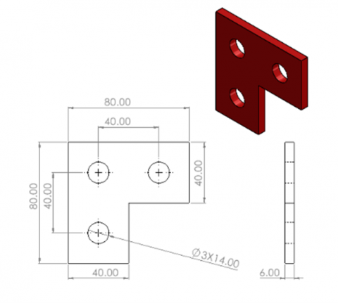
In this section, a specific and famous used product will be selected to design the compound die and do a study on it. This product is a joint plate containing 3 holes as in Figure 2.
The joint plate, which was selected for the study, is recognized for its crucial role across a wide range of industrial applications, necessitating high levels of manufacturing precision and durability. Traditionally, the fabrication of such plates has been characterized by the necessity for multiple steps and workstations, often involving up to four strokes across various dies, which has led to increases in both production time and costs. Conversely, through the research conducted, an innovative solution has been proposed, involving the development of a compound die that can manufacture the joint plate in a single stroke. This advanced method has significantly reduced the need for multiple workstations and iterative processes, thereby not only diminishing the time and effort required for production but also substantially enhancing both efficiency and accuracy. The introduction of a cost-effective alternative to address the conventional challenges associated with the fabrication of the joint plate, by the deployment of the compound die, has been seen as a critical advancement in manufacturing processes, contributing substantially to the field of manufacturing engineering.
Figure 2. Stainless steel L-shape bracket plate with 3 holes [11]
3.1 Product specifications and model
These fittings are available in various sizes and materials to cater to different requirements. L-shaped brackets are used in combination with channel nuts and bolts to create a robust connection, eliminating the need for welding. Once installed, they form a durable union that provides strength and stability to the overall structure. These fittings are designed to seamlessly integrate with Unistrut channels, ensuring a secure and reliable assembly [11]. Through research, the dimensions of such products are 80×80 or 86×86 or 90×90. As for the thickness, it ranges between 5 or 6 mm and usually these products are manufactured from 316 stainless steel or hot dipped galvanized [11]. The material chosen for the sheet metal (product) to be cut is 316 stainless steel and its dimension in Figure 3.
Figure 3. Product drawing that clarifies all dimensions
3.2 Compound die design for the product
3.2.1 Forces, energy, and other sheet parameters calculations
From the shape of the product, as it was clarified, the compound template must perform two operations, the first is blinking to cut the outer shape (L shape), and the second is piercing to cut the 3 holes. The two cutting forces (Blanking force) and (piercing force) can be calculated from the equations below [12]:
${{F}_{Bl}}=S\times t\times {{L}_{Bl}}$ (1)
L: It is the perimeter of the cutting region.
t: The thickness of the product.
S: The shear Strength of the product.
By using Eq. (1):
\[{{L}_{Bl}}=80+40+40+40+40+80=320~\text{mm}\]
\[{{L}_{pr}}=2\times \pi \times 7=43.98\text{ }\!\!~\!\!\text{ mm}\]
S = 0.6$\times {{S}_{ultamite~of~almnium}}=0.6\times 550=330~\text{Mpa}.$
The value of ${{S}_{ultamite\text{ }\!\!~\!\!\text{ }of\text{ }\!\!~\!\!\text{ }almnium}}$ is from the following reference [13]. So, the blanking force will be:
${{F}_{Bl}}=330\times 6\times 320=633.600\text{ }\!\!~\!\!\text{ kN}$
And the total pricing force will be:
${{F}_{pr}}=3\times \left( S\times t\times {{L}_{pr}} \right)$ (2)
${{F}_{pr}}=3\times \left( 330\times 6\times 43.98 \right)=261.21~kN$
The total cutting force:
${{F}_{Total~cutting}}=~{{F}_{Bl}}+~{{F}_{pr}}=894.81~kN$
For the clearance it could be calculated by equation below [12]:
$c=0.0032\times t\times \sqrt{S}$ (3)
$c=0.0032\times 6\times \sqrt{330}=0.07~mm$
So, the length and width of the blanking punch face and hole die diameter can calculate using equations below [11]:
${{L}_{bl}}=Length~of~product~face-2\times c$ (4)
${{L}_{bl}}=80-2\times 0.07=79.86~\text{mm}$
${{w}_{bl~}}=width~of~productface-2\times c$ (5)
${{w}_{bl~}}=80-2\times 0.07=79.86~\text{mm}$
$Hole~die~diameter=~{{D}_{h}}+2\times c$ (6)
$Hole~die~diameter=~14+2\times 0.07=14.14~\text{mm}$
The stripping force was calculated using the equation below and was taken as 10% of the value of the total cutting force [14].
$F_{\text {st }}=(5 \%-20 \%) \times F_{{\ Total\ cutting }}$ (7)
$F_{s t}=10 \% \times 894.81=89.581 \mathrm{\ kN}$
So, the total force or total press capacity of the die will be:
${Total\ Press\ Capacity}=894.81+89.481=984.291\text{ }\!\!~\!\!\text{ kN}$
$\text{In }\!\!~\!\!\text{ Tons}:~\frac{984.291}{9.81}=100.33~\text{Tons}$
For cutting energy and deformation work the two equations below will use [15, 16]:
$E=10~\times {{F}_{Total~cutting}}\times {{D}_{sd}}$ (8)
where,
E: Total cutting energy, kJ.
${{D}_{sd}}$: Sheard depth or sheet metal thickness, mm.
$E=10~\times 894.81\times 6=53.69~kJ$
where,
$K:$ Coefficient deepens on sheet metal thickness and shear strength of the material.
$F:$ Deformation force (or total cutting force), N.
$T:$ Sheet metal thickness, mm.
The value of K it is dependent on the material thickness and shear strength value and can found from the table in the following reference [16].
$W=K\times F\times T$ (9)
$W$ = $0.35\times 894.81\times 6=1879.101~kN.mm$
3.2.2 Punches design
After cutting forces calculations, the first step when designing a punch is to know the maximum length of the piercing punch by the below equation [17]:
$~{{L}_{pmax}}=~\frac{\pi \times d}{8}\times \sqrt{\frac{E\times d}{S\times t}}$ (10)
The modulus of elasticity (E) of 316 stainless steel is 193 Gpa [13]. So, the maximum length of the piercing punch is:
${{L}_{pmax}}=~\frac{\pi \times 14}{8}\times \sqrt{\frac{193\times 1000\times 14}{330\times 6}}=203.09~\text{mm}$.
The length of piecing punch should not exceed the above value so, the selected length of the piecing punch is 84 mm, because in these types of applications depending on the sheet metal thickness the length is between 50 to 125 mm [15].
The buckling force on the piecing punch could be calculate be equation below [18]:
${{F}_{cr}}=\frac{2\times \pi \times E\times {{I}_{min}}}{{{l}^{2}}}$ (11)
where,
$l$: Length of punch, mm.
$E:$ Modulus of elasticity, Mpa.
${{I}_{min}}:$ Minimal moment of inertia, m2.
${{I}_{min}}=\frac{\pi \times {{d}^{4}}}{64}$ (12)
${{I}_{min}}=\frac{\pi \times {{14}^{4}}}{64}$=$1885.75\text{ }\!\!~\!\!\text{ m}{{\text{m}}^{4}}$
so, the critical force will be:
${{F}_{cr}}=\frac{{{\pi }^{2}}\times 193\times 1000\times 1885.75}{4\times {{84}^{2}}}=127.27~\text{kN}$
The force on each piercing punch is $\frac{{{F}_{pr}}}{3}=87.07~\text{kN}~<$ ${{F}_{cr}}$, so there is no buckling occur on piercing punch.
For length of blanking die it is selected depending on the assembly and geometry length (98.5 mm) and take another out of profile clearance which is 5 mm to fixed blanking punch in lower holder plate.
The maximum compressive stress on punch could calculate by the following equation [14]:
${{\sigma }_{comp}}=\frac{{{F}_{punch}}}{{{A}_{punch}}}\le \sigma $ (13)
where,
${{\sigma }_{comp}}:$ The maximum compressive stress on punch, Mpa.
$\sigma $: Maximum stress can punch withstand it before deformation, Mpa.
${{F}_{punch}}:$ Punching force, N.
${{A}_{punch}}:$ Cross section area of punch, mm2.
For piecing punch:
${{\sigma }_{comp}}=\frac{87.08\times 1000}{\frac{\left( \pi \times {{14}^{2}} \right)}{4}}=565.82~\text{Mpa}~$
For blanking punch:
${{\sigma }_{comp}}=\frac{633.6\times 1000}{4326.19}=80.547~\text{Mpa}$
3.2.3 Die block or blanking die design
For the sake of more accuracy and to avoid any problems during the cutting process, the profile in Figure 4 was chosen, and this means that there is a number of parameters that must be calculated, such as (e, A, and B) and these parameters depend on total thickness (H) of die block.
Figure 4. Die block dimensions after a small clearance was add [15]
So, the equation to calculate thickness of die block ($H)$ is [15]:
$H=\left( 10+5\times t+0.7\times \sqrt{a+b+{{a}_{1}}+{{b}_{1}}} \right)\times c$ (14)
where:
${{a}_{1}}$: Related to the length of Sheet metal or workpiece.
${{b}_{1}}:$ Related to the width of Sheet metal or workpiece.
$a:$ Related to the little clearance of the length of sheet metal or workpiece.
$b$: Related to the little clearance of the width of sheet metal or workpiece.
Data:
${{a}_{1}}=80\text{ }\!\!~\!\!\text{ }mm$, ${{b}_{1}}=80\text{ }\!\!~\!\!\text{ }mm$,$\text{ }\!\!~\!\!\text{ }a=90\text{ }\!\!~\!\!\text{ }mm$; $b=80\text{ }\!\!~\!\!\text{ }mm$,
T=6 mm; $c=0.9$ from the following reference [18]:
$H=\left( 10+5\times 6+0.7\times \sqrt{90+90+80+80} \right)\times 0.9=47.6\text{ }\!\!~\!\!\text{ mm}\approx 48\text{ }\!\!~\!\!\text{ mm}$.
The below equation uses to calculate the e value which is the wall thickness as shown in the Figure 4 [18]:
$e=\left( 10~\text{to}~12 \right)+0.8\times H$ (15)
$e=10+0.8\times 48=48.4~\text{mm}$
To find the total length (A) and width (B) of die block the equations below are used [18].
$A~={{a}_{1}}+2\times e$ (16)
$A~=80+2\times 48.4=177\approx 180~\text{mm}$
$B~={{b}_{1}}+2\times e$ (17)
$B~=80+2\times 48.4=177\approx 180~\text{mm}$
The total length ($A)$ and width ($B)$ of other parts of die is the same of total length and width of blanking die, except the upper and lower base plate.
The calculation of the maximum stress on the die block is done using the equation below [18, 19]:
${{\sigma }_{db}}=\frac{{{F}_{bl}}}{{{A}_{db}}}\le {{\sigma }_{dbmax}}$ (18)
${{\sigma }_{db}}=\frac{633.6\times 1000}{180\times 48}=\frac{633600}{8640}=73.34~Mpa~$
3.2.4 Stripper plate design
Since the total thickness of the die block or plinking die block has been calculated, it is possible to calculate the thickness of the stripper plate from equation below [17]:
${{t}_{str}}=0.5\times H$ (19)
${{t}_{str}}=0.5\times 48=24~\text{mm}$
The stress on stripper plate can calculate by using below equation [20]:
${{\sigma }_{st}}=~\frac{{{F}_{Total~force}}}{{{A}_{st}}}\le {{\sigma }_{str~max}}$ (20)
${{\sigma }_{st}}=~\frac{984.291\times 1000}{24\times 180}=227.84~Mpa$
Deflection of movement stripper plate could calculate using the following equation [17]:
${{y}_{stripper}}=t+2~\text{mm}$ (21)
${{y}_{st}}=6+2~\text{mm}=8~\text{mm}$
Some dimensions such as 17 mm and 23.85 mm as in the stripper plate are related to the screws and springs and it will be clarified in the coming analysis.
3.2.5 Blank holder
The design of this piece depends on the rest of the parts and the requirements of shape and design.
3.2.6 Upper and lower holder plate
The thickness of these two parts is equal and can be calculated by the equation below [8]:
${{T}_{hold}}=0.75\times H$ (22)
${{T}_{hold}}=0.75\times 48=36~\text{mm}.$
3.2.7 Backup or backing plate design
Thicknesses are usually chosen between 6 and 12 mm. And sometimes it reaches 15, especially for applications where the thickness of the product is more than 5 mm [21].
3.2.8 Top base and bottom base plates design
These two plates are the thickest two parts in the die. The thickness of the top and bottom plates is calculated from the equations below.
${{T}_{top}}=1.25\times H$ (23)
${{T}_{top}}=1.25\times 48=60~\text{mm}$
${{T}_{Bottom}}=1.75\times H$ (24)
${{T}_{Bottom}}=1.75\times 48=84\text{ }\!\!~\!\!\text{ mm}$
The stress value on the top and bottom plate can be calculated using the equations below, knowing that the top and bottom plate are affected by 80% of the total cutting force [19].
${{\sigma }_{top~or~bottom}}=\frac{0.8\times {{F}_{Total~cutting}}}{{{A}_{top~or~bottom}}}$ (25)
${{\sigma }_{top}}=\frac{0.8\times 894.84\times 1000}{60\times 280}=42.61~\text{Mpa}$
${{\sigma }_{bottom}}=\frac{0.8\times 894.84\times 1000}{84\times 280}=30.44~\text{Mpa}$
3.2.9 Spring design
Four springs will be used in this research, which is the most common number. In the beginning, the maximum force acting on the spring must be calculated, and this is done using equation below [17].
${{F}_{spring,max}}\ge 1.5\times \frac{{{F}_{st}}}{i}$ (26)
${{F}_{spring,max}}\ge 1.5\times \frac{89.481}{4}$; ${{F}_{spring,max}}\ge 33.55~kN$
Using equation below the maximum deflection on the spring can be calculated [17]:
${{y}_{spring,max}}=\left( 3\text{ }\!\!~\!\!\text{ to}~4 \right)\times {{y}_{st}}$ (27)
${{y}_{spring,max}}=4\times 8=32~\text{mm}$
The minimum clearance $C{{~}_{min}}$ between the spring and its cavity (screw) must be calculated by equation below [22]:
$C{{~}_{min}}=0.05~\times {{D}_{screw}}$ (28)
The wire diameter ($d)$ that selected for this compressive spring is 3 mm.
Total number of coil (${{N}_{t}})$ is 11.5 turn.
Knowing that the diameter of the screw in which the spring will be is 17 mm so, the minimum clearance ${{C}_{min}}$:
$C{{~}_{min}}=0.05~\times 17=0.85~mm$
The inner diameter of spring can calculate by equation below [23]:
$ID={{D}_{screw}}+~{{C}_{min}}$ (29)
$ID=17+0.85=17.85~\text{mm}$
For outer and mean diameter, the equations below can use [24].
$OD=~ID+~2\times d$ (30)
where,
$d:$ The wire diameter, $\text{mm}$
$OD=17.85+~2\times 3=23.85~\text{mm}$
${{D}_{m}}=OD-d$ (31)
where,
${{D}_{m}}:$ Mean diameter of spring, mm.
${{D}_{m}}=23.85-3=20.85~\text{mm}$
Because the type of spring end here is Squared and Closed, the solid length (${{l}_{s}}$ )of the spring which is the length of the spring when its loaded can calculate by equation below [23]:
${{l}_{s}}=d\times $(${{N}_{t}}$) (32)
where,
$d:~$Wire diameter
${{N}_{t}}:$ Total colis
${{l}_{s}}=3\times 11.5=34.5~\text{mm}$.
The total length of the compressive spring is calculated by the equation below:
${{l}_{o}}={{y}_{spring,max}}+~{{l}_{s}}$ (33)
${{l}_{o}}=34.5+32=66.5\text{ }\!\!~\!\!\text{ mm}$
One of the most important things is also to make sure that the full length of the spring will not cause buckling to happen to it, and the equation below is used to make sure of this [23].
$~{{l}_{o}}<2.63\times \frac{{{D}_{m}}}{\alpha }$ (34)
where,
$\alpha :~$End-Condition Constants
The value of the $\alpha $ can get from the following reference [24]. Because of the two ends are fixed the value of $\alpha ~\text{is }\!\!~\!\!\text{ 0}\text{.5}.$ So,
$66.5<2.63\times \frac{20.85}{0.5}$
$66.5<109.671~$
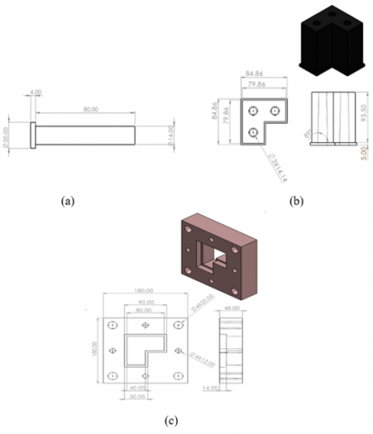
So, the calculating length of the compressive spring is safe. Figures 5 to 8 show all the compound die parts after being drawn by SOLIDWORKS software with all the dimensions.
Figure 5. Compound die parts: (a) Piercing punch, (b) Blanking punch, (c) Blanking die
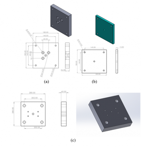
Figure 6. (a) Stripper plate, (b) Blank holder, (c) Lower holder plate
Figure 7. (a) Upper holder plate, (b) Backup plate, (c) Bottom base plate
Figure 8. (a) Base plate, (b) Compressive spring
Figure 9. Bill of material of compound die after assembly
Figure 9 shows the full compound die after assembly. After completion of the necessary calculations for each component of the die tailored to the design requirements of the specific item intended for production, the parts were subsequently illustrated after being meticulously designed in SolidWorks, accurately reflecting the dimensions derived from these calculations. The accompanying images provide a comprehensive depiction of the components, elucidating the assembly method employed. To prevent any potential issues during the manufacturing phase, a thorough review of all relevant factors was conducted. Consequently, the clearance calculations, deemed essential for the design's success, were carefully executed and incorporated into the SolidWorks design stage. The images below are set to demonstrate this process in detail. This methodical strategy ensures that the design is not only aligned with theoretical expectations but is also practically applicable, facilitating a smooth transition to the manufacturing stage. The process underscores a careful balance between precision in design and the practicalities of manufacturing, aiming to deliver a product that meets both design and operational criteria without complications.
3.3 Analysis and simulations using ANSYS workbench
In this section, the use of ANSYS software for the analysis of stresses, deformation, and the calculation of safety factors among other parameters will be discussed. This analysis will focus on key components of the die, such as the piercing punch and blanking punch. These components are typically manufactured from the same material to ensure they can withstand various cutting forces and maintain structural integrity during operations. For the simulations, two different materials commonly used in the manufacturing of punches and dies will be compared: AISI O1 (Oil-hardening) Tool Steel and AISI D2 Cold Work Tool Steel. The properties of each material are detailed in Table 1 and Table 2. The objective of this comparison is to ascertain the compatibility of these materials with the manufacturing process of the product and to provide a comparative analysis between them.
Table 1. AISI D2 steel mechanical properties [24, 25]
|
Properties |
Value |
|
Density (kg/m3) |
7670 |
|
Modulus of Elasticity (Gpa) |
190 |
|
Poisson’s Ratio |
0.28 |
|
Tensile Strength, Yield (Mpa) |
1510 |
|
Tensile Strength, Ultimate (Mpa) |
2000 |
|
Compressive Strength, Yield (Mpa) |
1650 |
Table 2. AISI O1 steel mechanical properties [26, 27]
|
Properties |
Value |
|
Density (kg/m3) |
7830 |
|
Modulus of Elasticity (Gpa) |
190 |
|
Poisson’s Ratio |
0.29 |
|
Tensile Strength, Yield (Mpa) |
1500 |
|
Tensile Strength, Ultimate (Mpa) |
1690 |
|
Compressive Strength, Yield (Mpa) |
1350 |
The type of analysis that will be conducted is the Fatigue Failure analysis by adding fatigue tool in ANSYS, because the components perform many operations per minute. Such products are manufactured hundreds or thousands of them daily. This means that the forces affecting the punches will change from zero to the maximum force (which is the cutting force).
In addition to the theoretical results that were reached previously, in this section the results obtained from the ANSYS software will be reviewed on the parts that were simulated using the 2 different materials, where the results of maximum stress and maximum deformation will be reviewed, as well as the safety factor.
4.1 Results when the material is AISI D2
4.1.1 Piercing punch
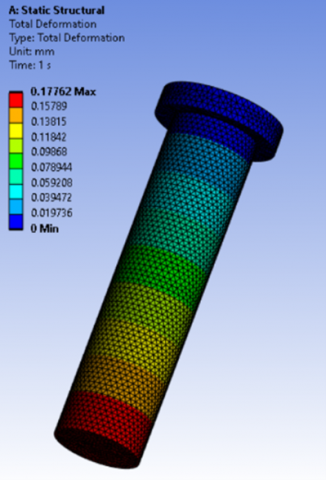
Figure 10 below shows the maximum stress and deformation for piercing punch in this case. Figure 11 shows the safety factor.
Figure 10. Results for a piercing punch made of AISI D2: (a) Maximum stress, (b) Total deformation
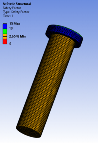
Figure 11. Safety factor of piercing punch made of AISI D2
The factor of safety is 2.65 (safe because it is larger than 1).
4.1.2 Blanking punch
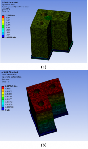
Figure 12 shows the maximum stress and deformation for blanking punch in this case. Figure 13 shows the safety factor.
Figure 12. Blanking punch made of AISI D2 results: (a) Maximum stress, (b) Total deformation
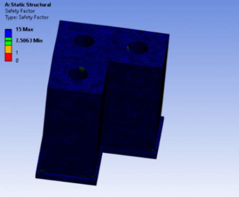
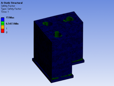
Figure 13. Safety factor of blanking punch made of AISI D2
The factor of safety is 7.506 (safe because it is larger than 1).
4.2 Results when the material is AISI O1
4.2.1 Piercing punch
As for the maximum stress (Von-mises), it will be reviewed in each part only once, because it is not affected by the type of material, but rather by the force and the area of the cross-section that affect it. Therefore, each part will have the same stress on the 2 materials. Figures 14 and 15 below show the total deformation and safety factor for this case.
Figure 14. Total deformation of piercing punch made of AISI O1
Figure 15. Safety factor of piercing punch made of AISI O1
The factor of safety is 2.65 (safe because it is larger than 1).
4.2.2 Blanking punch
Figures 16 and 17 show the total deformation and safety factor for this case.
Figure 16. Total deformation of blanking punch made of AISI O1
Figure 17. Safety factor of blanking punch made of AISI O1
The factor of safety is 6.54 (safe because it is larger than 1).
In the comparative analysis of AISI D2 and O1 materials for piercing and blanking punches, critical performance metrics such as stress response, deformation, and safety factor were examined. AISI D2 exhibited a maximum stress of 568.77 MPa and a deformation of 0.177 mm for the piercing punch, demonstrating substantial resistance to operational forces. For the blanking punch, it showed a stress of 22.967 MPa and a deformation of 0.075 mm, reinforcing its suitability. In contrast, O1 mirrored D2 in deformation but maintained consistent stress values for both punches, indicating material choice does not significantly affect maximum stress under the tested conditions. The safety factor for D2 slightly exceeded that of O1, with 2.65 for the piercing punch and 7.50 for the blanking punch, compared to 2.64 and 6.54 for O1, respectively. This suggests a marginal superiority of AISI D2 in terms of reliability and durability under the given parameters.
In conclusion, this study has highlighted the crucial role that modeling, and simulation play in metal forming, with a focus on the design of compound dies for sheet metal processing. The utilization of Computer-Aided Design (CAD) and Computer-Aided Engineering (CAE) tools, specifically SOLIDWORKS for modeling and ANSYS Workbench for simulation, facilitated enhancements in design precision and efficiency in manufacturing. The analysis of AISI D2 and AISI O1 tool steels guided the selection of materials, impacting cost and durability considerations in the metal forming process.
It is recommended that the die, which has been designed, simulated, and analytically assessed in this research, be manufactured in the future to produce the specified component. This step is advocated to validate the practical applicability of the research findings, bridging the gap between theoretical study and industrial application. The manufacturing of the designed die and the production of the component with it are expected to contribute significantly to the advancement of mechanical engineering by demonstrating the feasibility and effectiveness of the proposed solutions in real-world manufacturing settings.
This study was funded by Altinbas University.
[1] Sheet Metal Cutting. Tristatefabricators. https://tristatefabricators.com/sheet-metal-cutting/, accessed on 22 November 2023.
[2] Nie, F.R., Li, H.W., Li, Y.H., Yang, L.L. (2010). The design of bending parts compound die. Advanced Materials Research, 148-149: 312-315, 2010. https://doi.org/10.4028/www.scientific.net/AMR.148-149.312
[3] Yang, Z.Y., Fan, G.Q. (2011). A Study on the design of compound die with constant blank holder pressure. Applied Mechanics and Materials, 55-57: 2182-2184. https://doi.org/10.4028/www.scientific.net/AMM.55-57.2182
[4] Potočnik, D., Dolšak, B., Ulbin, M. (2013). GAJA: 3D CAD methodology for developing a parametric system for the automatic (Re) modeling of the cutting components of compound washer dies. Journal of Zhejiang University: Science A, 14(5): 327-340. https://doi.org/10.1631/jzus.A1200245
[5] Kashid, S., Kumar, S. (2014). Prediction of life of compound die using artificial neural network (ANN). Key Engineering Materials, 622-623: 664-671, 2014. https://doi.org/10.4028/www.scientific.net/KEM.622-623.664
[6] Pawar, S.S., Dalu, R.S. (2014). Computer assisted compound die design: A case study. International Journal of Research in Engineering and Technology, 3(5): 465-469. https://doi.org/10.15623/IJRET.2014.0305085
[7] Shrivastava, Verma, A., Ganguly, S.K. (2015). Design of compound die for production of cutting blades for nonactive rotary paddy weeder. Materials and Manufacturing Processes, 30(12): 1412-1416. https://doi.org/10.1080/10426914.2014.973601
[8] Patil, R.A., Panchal, A.T. (2017). Design of die for industrial part. In International Conference Proceeding ICGTETM, Bambhori, Jalgaon, pp. 140-144.
[9] Jyothirmayi, N., Rao, D.B.V.S. (2019). The design and fabrication of a compound die to make hexagonal washer. International Journal of Mechanical and Production Engineering Research and Development (IJMPERD), 9(4): 517-528, 2019. http://doi.org/10.24247/ijmperdaug201951
[10] Gaikwad, S.B., Sonawane, J.B., Kalamkar, K.L., Kale, A.B. (2019). Design and development of compound die. In Proceedings of Second Shri Chhatrapati Shivaji Maharaj QIP Conference on Engineering Innovations, Shri Chhatrapati Shivaji Maharaj College of Engineering, Ahmednagar, pp. 405-408.
[11] RS PRO. (2023). Stainless steel L shape bracket 3 hole, 86×86mm. https://uk.rs-online.com/web/p/flat-fittings/2216342?gb=s, accessed on 22 November 2023.
[12] Groover, M.P. (2019). Fundamentals of Modern Manufacturing Materials, Processes, and Systems. Seventh Edition, Wiley.
[13] MW Components. (2023). Stainless steel 316 - Elgin fasteners. Elgin Fastener Group. https://www.elginfasteners.com/resources/materials/material-specifications/stainless-steel-316/, accessed on 22 November 2023.
[14] Venkataraman, K. (2022). Design of Jigs, Fixtures and Press Tools. https://doi.org/10.1007/978-3-030-76533-0
[15] Shaheen, W. (2019). Optimization of compound die design with double cutting process parameters and stress analysis using theoretical, numerical and statistical methodology. PHD Thesis, University of New South Wales. https://doi.org/10.26190/unsworks/21582
[16] Oberg, E., Jones, F.D., Horton, H.L., Ryffel, H.H., McCauley, C.J. (2020). Machinery’s Handbook. Industrial Press, Inc.
[17] Tigges, H.L. (1970). A Text Book of Production Engineering. Production Engineer, MADE EASY Publications. https://doi.org/10.1049/tpe.1970.0036
[18] Boljanovic, V. (2014). Sheet Metal Forming Processed and Die Design. Industrial Press, Inc.
[19] Subrahmanyam, M., Mokhalingam, A. (2016). Design and analysis of press tool to produce radiator stay bracket. International Journal of Engineering Research & Technology (IJERT), 5(6): 829-835. https://doi.org/10.17577/IJERTV5IS060802
[20] Mastanamma, C., Rao, K.P., Rao, M.V. (2012). Design and analysis of progressive tool. International Journal of Engineering Research & Technology, 1(6): 1-10.
[21] Reddy, V.V., Mutyalu, K.B., Reddy, S.S., Nayak, M.R. (2021). Modelling and manufacturing of progressive die for mechanical press operations. Turkish Journal of Computer and Mathematics Education, 12(3): 3662-3671. https://doi.org/10.17762/turcomat.v12i3.1647
[22] Suchy, I. (2006). Handbook of Die Design. New York: McGraw-Hill Education.
[23] Budynas, R.G., Richard, J.K.N. (2020). Shigley’S Mechanical Design Engineering. McGraw-Hill Education.
[24] Matweb. (2023). Bohler-Uddeholm AISI D2 Cold Work Tool Steel. https://www.matweb.com/search/datasheet_print.aspx?matguid=bcbf506c860444a08a1ff23635b6815f, accessed on 22 November 2023.
[25] MakeItFrom. (2023). Hardened D2 Tool Steel. https://www.makeitfrom.com/material-properties/Hardened-D2-Tool-Steel, accessed on 22 November 2023.
[26] MakeItFrom. (2023). SAE-AISI O1 (T31501) Oil-Hardening Steel. https://www.makeitfrom.com/material-properties/SAE-AISI-O1-T31501-Oil-Hardening-Steel, accessed on 22 November 2023.
[27] MatWeb. (2023). AISI Type O1 Oil-Hardening Tool Steel, Oil Quenched at 800℃, Tempered at 425℃. https://www.matweb.com/search/datasheettext.aspx?matguid=42da7db7f74041a98f3ee0239b4c6ac6, accessed on 22 November 2023.