Hisham A. Hoshi | Akram H. Abed![]() | Huda A. Al-Salihi | Farhan Lafta Rashid*
| Huda A. Al-Salihi | Farhan Lafta Rashid*![]() | Awesar A. Hussain
| Awesar A. Hussain
© 2024 The authors. This article is published by IIETA and is licensed under the CC BY 4.0 license (http://creativecommons.org/licenses/by/4.0/).
OPEN ACCESS
The characteristics of heat transmission in a cylindrical tube equipped with novel geometric turbulators inserts were investigated experimentally. The effects of two geometric parameters (ratio of pitch P=L/D and interior angle) on fiction factor, Nusselt number, the thermal executions were tested and compared with a smooth tube for the same conditions. Reynolds number ranged from 4293 to 14310, with interior angles of 20°, 60°, and 95°, and pitch ratios between 4.44 and 5.83. The relation between friction factor and Nusselt number for practical applications have successfully predicted. It was revealed that friction factor, Nusselt number, and thermal performance enhanced with reducing the pitch ratio and the interior angle. Nusselt number raised by 91,117 and 154%, friction factor enhanced by 82.7, 105.3 and 136.1 compared with smooth tube at ratio pf pitch L/D=4.44 and interior angle θ=20°. The factor of thermal performance was discovered to be larger than the unity for all arrangements and the maximum value obtained at η=2.2.
heat exchanger, heat transfer, thermal performance factor, geometric turbulator inserts, turbulator geometry
Techniques of heat transmission improvement are applied in many industrial purposes like refrigeration, heat exchanger, chemical industries and other manufacturing processes [1-4]. These technical methods are categorized into two major methods. The first method needs an outer energy source such as the vibration of the fluid or the electrostatic field or the mechanical aids. While, the passive style, which doesn’t require a source of external power. This method is considered to be more efficient to fabricate and low cost [5-7]. The most important of these turbulators is the twisted tape which changes the flow to a swirl flow. This flow conversion result in a reduction in the boundary layer thickness as well as enhance the coefficient of heat transmission [8-20]. Other important turbulators are helical screw tape [21-23]. Inserts for tubes have the potential to significantly increase heat transmission inside the tubes [24-28].
Akhavan-Behabadi et al. [29] obtained characteristics of heat transmission in the circular tube for constant heat flow. It was revealed that the lowering in the pitch of coil and enhance wire diameter leads to enhance heat transfer rate and friction coefficient. Reddy and Rao [30], investigated the influence of the wire coil inserts on the friction coefficient and heat transmission of nanofluid in the double-pipe heating exchanger (HE). It was observed a significant enhancement in the rate of heat transmission, but an undesirable drop in the pressure.
Keklikcioglu and Ozceyhan [31] studied the influence of inserting an equilateral triangular coil wire in the cylindrical tube on thermal-hydraulic effectiveness. The wire was installed at a distance of 1 and 2 mm from the interior dike of the tube with three ratios of pitch and its edge was facing the incoming airflow. The findings indicated that the friction factor and transfer of heat with wire coil inserted in the tube were greater than in the smooth tube. Also, it was found that thermo-hydraulic effectiveness was best with 1 mm distance and thermal efficiency of 82%. Man et al. [32] inspected the heat transfer characteristics for the flow of forced convection of the counterclockwise and clockwise of entangled strip inserted inside double tube HE. The entangled strip lengths with different Reynolds number range were considered. It was found that there was an improvement in the performance of twist tape. Also, length 1.42 showed better performance than other lengths.
San et al. [33] revealed the influence of the wired coil at different wire diameters. The influence of the coiled pitch of the ratio of inner tube diameter was also observed. The findings presented that Nusselt number enhances with increasing the ratio of the wire diameter. In addition, it was proved that Nusselt number enhances with lowering the ratio of the coiled pitch to the inner diameter of tube.
Sadeghi et al. [34] examined the characteristics of heat transmission in the nanofluid which flows through the tubes with the insertion of a helical tape. It was found that the decreasing ratio of twist in the helical strip to increase friction factor and Nusselt number.
This work aims to study the characteristics of heat transmission and drop in pressure of novel geometric turbulator in a slick cylindrical tube, considering two parameters: interior angle (θ=20°, 60°, and 95°) and pitch ratio (P=L/D=5.83 and 4.44). Additionally, a new correlation is sophisticated to estimate friction factor and Nusselt number by specific geometric parameters.
2.1 Experimentation
The test section comprises a copper pipe with length 1390 mm, inner diameter of 45 m, and thickness of 1.5 mm. For the purpose of reducing the heat losses, the pipe was insulated asbestos rope 25 mm thick. The novel turbulators were connected to the internal pipe surface. It should be noted that the turbulator was made from aluminum metal, as shown in Figure 1. The larger and smaller base diameter were designed 35 mm, 10 mm, respectively. The length of the turbulator was designed 60 mm. The turbulators were arranged with various pitch ratios (P=(L/D)=5.83 and 4.44).
A band heater of 800 W was firmed about the outer surface. A transformer was utilized to monitor the output of electrical power at uniform heating flux which was produced in the test rig of the controller with heating flux. Pressure air on the other hand was measured by using blower 250 W. Surface temperatures were monitored by welding eighteen thermocouple k-type of different places through the testing section. To measure the temperatures of outlet and inlet air, two additional thermocouples were set at the exit and entrance of the pipe. The temperatures along the test section, air temperatures at the exit and entrance were recorded at a condition of steady state. The rate of air flow was measured by utilizing an orifice device. Taps of pressure that inserted at the downstream and upstream of the testing rig were attached to the digital manometer to observe the drop in pressure for evaluating the friction factor. The rate of air flow was measured by valve and an orifice device. Experimental rig is shown in Figure 1.
Figure 1. Sketch of the test rig and shape of turbulator
2.2 Data reduction
The factor of friction (f) is obtained by [35-39]:
$f=\frac{\Delta P}{\left(\frac{L}{D}\right)\left(\frac{\rho u^2}{2}\right)}$ (1)
The absorbed heat by air (Qair) is given by:
$\mathrm{Q}_{\text {air }}=\dot{\mathrm{m}}_{\mathrm{p}}\left(\mathrm{T}_{\mathrm{o}}-\mathrm{T}_{\mathrm{i}}\right)$ (2)
$\left[\frac{\left.\mathrm{Q}_{\mathrm{VI}}-\mathrm{Q}_{\mathrm{air}}\right)}{\mathrm{Q}_{\mathrm{VI}}}\right] \times 100 \%=5 \%$ (3)
The transfer of convection heat from the test section may be calculated by Eq. (4):
$\mathrm{Q}_{\text {cov }}=\mathrm{hA}\left(\mathrm{T}_{\mathrm{w}}-\mathrm{T}_{\mathrm{b}}\right)$ (4)
The absorbed heat from the air is considered [40-43]:
$\mathrm{Q}_{\mathrm{air}}=\mathrm{Q}_{\mathrm{cov}}$ (5)
The average coefficient of heat transmission may be calculated from:
$\mathrm{h}=\frac{\mathrm{mC}_{\mathrm{p}}\left(\mathrm{T}_0-\mathrm{T}_{\mathrm{i}}\right)}{\mathrm{A}\left(\overline{\mathrm{T}}_{\mathrm{w}}-\mathrm{T}_{\mathrm{b}}\right)}$ (6)
where, bulk mean temperature $\left(\mathrm{T}_{\mathrm{b}}\right)$ is defined as:
$\mathrm{T}_{\mathrm{b}}=\frac{\left(\mathrm{T}_{\mathrm{0}}+\mathrm{T}_{\mathrm{i}}\right)}{2}$ (7)
The average wall temperature is given by:
$\overline{\mathrm{T}}_{\mathrm{w}}=\sum \mathrm{T}_{\mathrm{w}} / 18$ (8)
Nusselt number may be calculated from:
$\mathrm{Nu}=\frac{\mathrm{hD}}{\mathrm{k}_{\mathrm{a}}}$ (9)
Thermal performance $(\eta)$ could be presented as the ratio of Nusselt number to friction factor of the smooth tube [13]:
$\eta=\frac{\frac{\mathrm{Nu}}{\mathrm{Nu}_{\mathrm{s}}}}{\left(\frac{\mathrm{f}}{\mathrm{f}_{\mathrm{S}}}\right)^{\frac{1}{3}}}$ (10)
2.3 Uncertainty analysis
The typical definition of the error that may be found in a result or measurement is the disparity that can be found between the actual value and the value that was computed or measured. This is only feasible in situations in which the actual value can be determined from a baseline result or via analytical solutions. Because of this, we are unable to say with certainty what the mistake may be in any of the other circumstances. The result of this is the introduction of the idea of uncertainty, which is applied to indicate a potential quantity that the mistake may have. However, the degree of uncertainty, or what one might assume the error to be, can change quite a bit depending on the specific conditions of the variable’s observations. By "variables," we mean the fundamental amount seen immediately in the experimentation, which are acquired by performing predictions using the listed variables values. The variables values are referred to as the data, and in certain instances the outcome will be the same as the data (when just one measurement is performed). The term "propagation of uncertainty" refers to the process by which the degree of unpredictability in one variable may influence the degree of unpredictability in another variable.
The Kline and McClintock procedures [44] was applied to estimate the error analysis (uncertainty) of the major heat transfer parameters. Values of error analysis are presented in Table 1. The equation used for this method is given below:
$\mathrm{W}_{\mathrm{R}}=\left\lceil\left(\frac{\partial \mathrm{R}}{\partial \mathrm{x}_1} \mathrm{~W}_1\right)^2+\left(\frac{\partial \mathrm{R}}{\partial \mathrm{x}_2} \mathrm{~W}_2\right)^2+\cdots\left(\frac{\partial \mathrm{R}}{\partial \mathrm{x}_{\mathrm{n}}} \mathrm{W}_{\mathrm{n}}\right)^2\right]^{\frac{1}{2}}$ (11)
$\mathrm{W}_{\mathrm{R}}$ refers to the error analysis (uncertainty) in the results.
$R$ refers to the independent variables $x_1, x_2, \ldots x_n ; R=R\left(x_1, x_2, \ldots x_n\right)$.
$W_1, W_2, \ldots W_{n=}$ error analysis (uncertainty) in the independent parameters.
Table 1. Experimental parameters error analysis
|
No. |
Instrument |
Accuracy |
Uncertainty |
|
1 |
K Type thermocouple |
±0.1℃ |
±0.5% |
|
2 |
Temperature indicator |
±0.1℃ |
±2% |
|
3 |
Tilted manometer |
±1 mm |
±6% |
|
4 |
Digital manometer |
±0.5 mm |
±5% |
|
5 |
Anemometer |
± 0.1 m /s |
±4% |
|
6 |
Ammeter |
±0.01 I |
±0.2% |
|
7 |
Voltmeter |
±0.1 V |
±0.2% |
|
8 |
Nusselt number |
- |
±4% |
|
9 |
Friction factor |
- |
±6% |
|
10 |
Reynolds number |
- |
±5% |
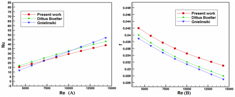
3.1 Validation
Results of the experimental part for the factors of friction and Nusselt numbers of the smooth tube without insert were compared with that from standard correlations to verify the reliability of the experimental orientation as presented in Figure 2 (A-B). Reynolds number ranged from 4293 to 14310, with interior angles of 20°, 60°, and 95°, and pitch ratios between 4.44 and 5.83. The effects of two geometric parameters (interior angle and pitch ratio P=L/D) on Nusselt number, fiction factor, examining the thermal performances and comparing with a smooth tube under the same circumstances. Nusselt numbers which obtained by Dittus-Boelter (Eq. (12)) [45] and Gnielinski (Eq. (13)) [46] were critically compared. While, friction factor results were compared between Blasius’s correlation (Eq. (14)) [47] and Petukhov (Eq. (15)) [48]. The higher deviation of the experimental and predicted quantities of friction factor and Nusselt number was found ±6.5%, ±6%. The obtained results exhibited a perfect behaviour with that presented in the literature and prove the reliability of the experimental setup to conduct the experiments using novel turbulators.
Dittus-Boelter̓s equation:
$\mathrm{Nu}=0.023 \mathrm{Re}^{0.8} \mathrm{Pr}^{0.4}$ (12)
Gnielinski ̓s relation:
$\mathrm{Nu}=\frac{(\mathrm{f} / 8)(\mathrm{Re}-1000) \mathrm{Pr}}{1+12.7(\mathrm{f} / 8)^{1 / 2}\left(\mathrm{Pr}^{2 / 3}-1\right)}$ (13)
Blasius correlation:
$\mathrm{f}=0.316 \mathrm{Re}^{-0.25}$ (14)
Petukhov correlation:
$f=(0.79 \ln R e-1.64)^{-2}$ (15)
3.2 Effect of the pitch ratio and interior angle on the Nusselt number
Novel geometric turbulators inserts and smooth tube without inserts were compared according to Nusselt numbers Figure 3 (A).
It is obvious to see that the characteristics of heat transfer exhibit similar tendency in the smooth tube. It is important to point out that enhancing the Reynolds number causes an enhance in the turbulence flow intensity, which in turn led to a raise in the heat transfer rate. Also, the tube turbulators insert exhibited a superior enlargement of the convective heating transmission if compared with smooth tube.
Figure 3 (A) shows the higher values of the Nusselt numbers with a small interior angle inserts compared with others. It is well knowledge that a modest angle will produce longitudinal vortices down the length of the tube [49]. This trend can be led to the thermal layer evolution. As soon as the fluid crosses through the turbulators, the small internal angle of the turbulators improves the flow rate between the core and the surface.
It should be noted that the fluid near the surface was substituted by another fluid in the center, since the gradients rises in temperature nearby the tube walls, which promotes heat transfer [50, 51].
Further, it can be seen from Figure 3 (A) that the Nusselt number rises with lowering the pitch ratio P=L/D of the turbulators. The reason for that was attributed to the small pitch ratio, which assist the flow recirculation and improve the intensity of flow turbulence.
The results show that the enhancement of the convective heating transmission was more apparent in the novel geometric turbulators inserts compared with that in the case of smooth tube. The values of Nusselt number enhances by 91, 117 and 154% of the tube with P=L/D=4.44 of novel geometric turbulators inserts and (95°, 60° and 20°) compared to the case of smooth tube.
Figure 2. Experimental and predictions correlations of friction factor and Nusselt number for smooth tube vs. Reynolds number
Figure 3. Variation of Nusselt number ratio (Nu /Nus) with Reynolds number
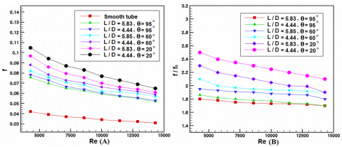
Figure 4. Variation of Reynolds number with friction factor and friction factor ratio
Figure 3 (B) shows that Nu/Nus rises with the lowering values of interior angle and pitch ratio P=L/D because of the high intensity of turbulence. However, the ratio of Nu/Nus exhibits a regular reduction as Re increase by 2. 06-2.98 times, which is reliant on Re, θ and P=L/D values. This indicates that applying a small interior angle cause a significant rise in the transfer of heat.
3.3 Influence of interior angle and pitch ratio on the factor of friction
Figure 4 (A) displays the factor of friction variations with Reynolds number for the case of smooth tube with novel geometric turbulators inserts. Obviously, the factor of friction declines with enhancing Reynolds number, since the highest friction factor value was observed in the novel geometric turbulators inserts. It was determined that the flow channel had been stopped by the innovative geometric turbulators, and that was the cause for what had happened. Hence, the stream velocity diverse from those in the smooth tube. Also, one can observe that the factors of friction were considerably higher with turbulators of the interior angle (95°, 60° and 20°) and p=L/D=4.44 and 5.83 compared with those in the smooth tube.
It should be noticed that the generation of the secondary flow in the novel geometric turbulators resulted by the unstable forces of shear. Thus, the fluid was moved toward the wall tube which resulted in the distortion of the axial velocity tendency along the tube. In point of fact, the secondary flow that was produced by the innovative geometric turbulators pushed fluid outward in order to strike a balance between the two vectors of momentum. As a consequence of this, there was an enhancement in the pressure of the flow [52].
Meanwhile, factor of friction was increased in the novel geometric turbulators as the pitch ratio decreased. That tendency is the same with Nusselt number.
It was found that friction factors were greater by 0.81, 1.06 and 1.4 in the tube installed with P=L/D=4.44 inserts (95°, 60° and 20°). However, Reynolds numbers observed from the range (4293–14310).
Figure 4 (B) displays ratios of friction factor for different values of Reynolds numbers. It can be seen that the ratio of friction factor reduces with a rising in Reynolds number, since factor of friction ratio with a small angle 20° was much higher than the other angles (60°, 95°). Also, friction factor ratio with a small angle 20° was greater than those in the large pitch ratio of entire Reynolds numbers. The average factors of friction were obtained 1.86, 2.1 and 2.5 greater than that in the smooth tube when L/D=4.44 with angles (95°, 60° and 20°).
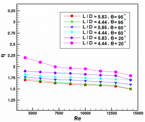
3.4 Effect of pitch ratio and interior angle on the thermal effectiveness
It was examined the plain tube as the baseline case. It was found that thermal performance of turbulators inserts enhances with a decrease in pitch ratio and interior angle. The largest factor of thermal effectiveness was observed in the small interior angle θ=20° with a pitch ratio of 4.44, followed by θ=60° and θ=95° with same pitch ratio. The thermal performance factors are found to be 1.73, 1.83, and 2.2 for the tube with the interior angle (95°, 60° and 20°) and p=L/D=4.44, respectively.
Figure 5. Relationship between overall enhancement ratio and Reynolds number
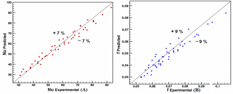
Figure 6. Predicted and experimental values comparison for Nusselt number (a) and factor of friction (b)
Figure 5 clarifies variation of the Reynolds number and enhancement ratio of the tube with turbulators, interior angle inserts (95°, 60° and 20°) and p=L/D=4.44 and 5.83. It was found that there was a dropping in the factor of thermal effectiveness when enhancing the Reynolds number. It's possible that the thick layer of the thermal barrier, which becomes thicker when rising the Reynolds number value, is to blame for it. When the Reynolds numbers were lower, turbulence in the thermal boundary layer could be seen.
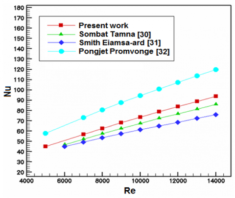
Figure 7. Comparison between Nusselt number in the present study with previous work
It should be noted that increasing Nusselt number was further evident than the rising of losses in friction when η ≥ 1.0. As mentioned before, thermal performance factor can be obtained by applying Eq. (10).
3.5 Development the empirical correlations
Two experiential correlations were improved depending on the experimental results to estimate Nusselt number and friction factor. This correlation can be applied in novel geometric tablets by applying air as fluid with Pr ≈ 0.7 at Re=4293-14310, D/L=4.44-5.83 and θ=20°-95° [53, 54].
$\mathrm{Nu}=0.23 \operatorname{Re}^{0.72} \operatorname{Pr}^{0.4}(1-\sin \theta)^{0.12}\left(\frac{\mathrm{L}}{\mathrm{D}}\right)^{-0.47}$ (16)
$f=9.32 R e^{-0.46}(1-\sin \theta)^{0.22}\left(\frac{L}{D}\right)^{-0.51}$ (17)
Comparison was made between the estimated and experimental results of friction factor and Nusselt number, which exhibited a slight difference between them, as shown in Figures 6. Also, it's obvious to see that the most values of the experimental results fall within (±7 to ±9) % of the estimated Nusselt number and friction factor. On the other hand, another comparison was conducted with the work that came before it, which presented an acceptable agreement between the two results. As shown in Figure 7, Nusselt number that were acquired in this study revealed a larger tendency compared to the ones that were obtained in the earlier researches [55-58]. This finding was observed.
Transfer of heat, factor of friction, and thermal effectiveness characteristics of circular tube fitted with novel geometric turbulators for interior angle (95°, 60° and 20°) with two pitch ratios (p=L/D=4.44 and 5.83) were examined. The most important conclusions can be summarized as follows:
1. Novel geometric turbulators (different interior angles of 20°, 60°, and 95°, and pitch ratios between 4.44 and 5.83), with angle θ=20° exhibited the highest rate of friction factor and transfer of heat, as well as thermal effectiveness in comparison with the smooth tube. The small angle generates longitudinal vortices along the tube. This leads to mix the air with different velocities and temperatures, which led to an increase in the gradient of temperature of the thermal boundary layer and cause a uniformity of fluid temperature in addition to enhance heat transfer.
2. Nusselt number and friction factor raised with decreasing the interior angle (θ) and pitch (p=L/D) ratio. Nusselt number for (θ=95°, 60° and 20°) and p=L/D=4.44 was found 1.92, 2.17 and 2.53 times higher in the smooth tube. In the smooth tube, the factor of friction was roughly 1.8, 2.02, and 2.33 times more than in the other tubes. The observed values for the performance factors were 1.73, 1.83, and 2.2.
3. Thermal performance factors were obtained over (1) which indicate to the improvement transfer of heat (Nusselt number in the presence of turbulator higher than that in the plain tube), since the highest overall enhancement ratio was gained around (2.2).
4. The empirical equations of Nusselt number and friction factor exhibited a satisfied assent with the results of experimental part. The divergences were 9% for friction factor and 7% for Nusselt number.
|
A |
Surface area (m2) |
|
Cp |
Heat capacity (J/kgK) |
|
D |
Tude diameter (m) |
|
h |
Coefficient of heat transfer (W/m2K) |
|
f |
Factor of friction (--) |
|
L |
Test section length (m) |
|
k |
Thermal conductivity (W/mK) |
|
T |
Air flow temperature (K) |
|
$\dot{m}$ |
Rate of mass flow (kg/s) |
|
Q |
Transfer of heat (W) |
|
u |
Air velocity (m/s) |
|
PR |
Pitch ratio (--) |
|
Pr |
Prandtl number (--) |
|
Re |
Reynolds number (--) |
|
Nu |
Nusselt number (--) |
|
Greek symbols |
|
|
i |
in |
|
o |
out |
|
a |
air |
|
s |
smooth (plain) tube |
|
Subscripts |
|
|
$\Delta \mathrm{P}$ |
Pressure drop (Pa) |
|
$\rho$ |
Density (kg/m3) |
|
θ |
Angle (degrees) |
[1] Hashim, W.M., Hoshi, H.A., Al-Salihi, H.A. (2019). Enhancement the performance of swirl heat exchanger by using vortices and NanoAluminume. Heliyon: 5(8): e02268. https://doi.org/10.1016/j.heliyon.2019.e02268
[2] Mahmud, M.J., Imtias, A., Hossain, M.R., Saha, S. (2022). Conjugate mixed convection heat transfer with internal heat generation in a lid-driven enclosure with spinning solid cylinder. Heliyon, 8(12): e11968. https://doi.org/10.1016/j.heliyon.2022.e11968
[3] Hasan, M.J., Ahmed, S.F., Bhuiyan, A.A. (2022). Geometrical and coil revolution effects on the performance enhancement of a helical heat exchanger using nanofluids. Case Studies in Thermal Engineering, 35: 102106. https://doi.org/10.1016/j.csite.2022.102106
[4] Colak, A.B., acikgoz, O., Mercan, H., Dalkilic, A.S., Wongwises, S. (2022). Prediction of heat transfer coefficient, pressure drop, and overall cost of double-pipe heat exchangers using the artificial neural network. Case Studies in Thermal Engineering, 39: 102391. https://doi.org/10.1016/j.csite.2022.102391
[5] Marzouk, S.A., Al-Sood, M.M.A., El-Said, E.M.S., El-fakharany, M.K. (2020). Effect of wired nails circular–rod inserts on tube side performance of shell and tube heat exchanger: Experimental study. Applied Thermal Engineering, 167: 114696. https://doi.org/10.1016/j.applthermaleng.2019.114696
[6] Jalili, B., Aghaee, N., Jalili, P., Ganji, D.D. (2022). Novel usage of the curved rectangular fin on the heat transfer of a double-pipe heat exchanger with a nanofluid. Case Studies in Thermal Engineering, 35: 102086. https://doi.org/10.1016/j.csite.2022.102086
[7] Sun, Z., Zhang, K., Li, W., Chen, Q., Zheng, N. (2020). Investigations of the turbulent thermal-hydraulic performance in circular heat exchanger tubes with multiple rectangular winglet vortex generators. Applied Thermal Engineering, 168: 114838. https://doi.org/10.1016/j.applthermaleng.2019.114838
[8] Nakhchi, M.E., Hatami, M., Rahmati, M. (2020). Experimental investigation of heat transfer enhancement of a heat exchanger tube equipped with double-cut twisted tapes. Applied Thermal Engineering, 180: 115863. https://doi.org/10.1016/j.applthermaleng.2020.115863
[9] Boonloi, W., Jedsadaratanachai, W. (2016). Turbulent forced convection and heat transfer characteristic in a circular tube with modified twisted tapes. Journal of Thermodynamics, 2016: 8235375. http://doi.org/10.1155/2016/8235375
[10] Liaw, K.L., Kurnia, J.C., Sasmito, A.P. (2021). Turbulent convective heat transfer in helical tube with twisted tape insert. International Journal of Heat and Mass Transfer, 169: 120918. https://doi.org/10.1016/j.ijheatmasstransfer.2021.120918
[11] Changcharoen, W., Somravysin, P., Eiamsa-ard, S. (2015). Thermal and fluid flow characteristics in a tube equipped with peripherally-cut dual twisted tapes. Open Engineering, 5(1): 89-98. https://doi.org/10.1515/eng-2015-0009
[12] Zhang, H., Nunayon, S.S., Jin, X., Lai, A.C.K. (2022). Pressure drop and nanoparticle deposition characteristics for multiple twisted tape inserts with partitions in turbulent duct flows. International Journal of Heat and Mass Transfer, 193: 121474. https://doi.org/10.1016/j.ijheatmasstransfer.2021.121474
[13] Chokphoemphun, S., Pimsarn, M., Thianpong, C., Promvonge, P. (2015). Thermal performance of tubular heat exchanger with multipletwisted-tape inserts. Chinese Journal of Chemical Engineering, 23(5): 755-762. https://doi.org/10.1016/j.cjche.2015.01.003
[14] Eiamsa-ard, S., Kiatkittipong, K., Jedsadaratanachai, W. (2015). Heat transfer enhancement of TiO2/water nanofluid in a heat exchanger tube equipped with overlapped dual twisted-tapes. Engineering Science and Technology, an International Journal, 18(3): 336-350. https://doi.org/10.1016/j.jestch.2015.01.008
[15] Eiamsa-ard, S., Nanan, K., Wongcharee, K. Yongsiri, K., Thianpong, C. (2015). Thermohydraulic performance of heat exchanger tube equipped with single-, double-, and triple-helical twisted tapes. Chemical Engineering Communications, 202(5): 606-615. https://doi.org/10.1080/00986445.2013.858038
[16] Piriyarungrod, N., Kumar, M., Thianpong, C., Pimsarn, M., Chuwattanakul, V., Eiamsa-ard, S. (2018). Intensification of thermo-hydraulic performance in heat exchanger tube inserted with multiple twisted-tapes. Applied Thermal Engineering, 136: 516-530. https://doi.org/10.1016/j.applthermaleng.2018.02.097
[17] Bhuiya, M.M.K., Roshid, Talukder, M.M.M., Rasul, M.G., Das, P. (2020). Influence of perforated triple twisted tape on thermal performance characteristics of a tube heat exchanger. Applied Thermal Engineering, 167: 114769. https://doi.org/10.1016/j.applthermaleng.2019.114769
[18] Famileh, I.Z., Esfahani, J.A. (2017). Experimental investigation of wet flue gas condensation using twisted tape insert. International Journal of Heat and Mass Transfer, 108: 1466-1480. https://doi.org/10.1016/j.ijheatmasstransfer.2017.01.001
[19] Chang, S.W., Cai, W.L., Syu, R.S. (2016). Heat transfer and pressure drop measurements for tubes fitted with twin and four twisted fins on rod. Experimental Thermal and Fluid Science, 74: 220-234. https://doi.org/10.1016/j.expthermflusci.2016.01.001
[20] Prasad, P.V.D., Gupta, A.V. (2016). Experimental investigation on enhancement of heat transfer using Al2O3/water nanofluid in a u-tube with twisted tape inserts. International Communications in Heat and Mass Transfer, 75: 154-161. https://doi.org/10.1016/j.icheatmasstransfer.2016.03.019
[21] Chougule, S.S., Sahu, S.K. (2015). Heat transfer and friction characteristics of Al2O3/ water and CNT/water nanofluids in transition flow using helical screw tape inserts–A comparative study. Chemical Engineering and Processing: Process Intensification, 88: 78-88. https://doi.org/10.1016/j.cep.2014.12.005
[22] Zade, N.M., Akar, S., Rashidi, S., Esfahani, J.A. (2017). Thermo-hydraulic analysis for a novel eccentric helical screw tape insert in a three dimensional tube. Applied Thermal Engineering, 124: 413-421. https://doi.org/10.1016/j.applthermaleng.2017.06.036
[23] Rashidi, S., Zade, N.M., Esfahani, J.A. (2017). Thermo-fluid performance and entropy generation analysis for a new eccentric helical screw tape insert in a 3D tube. Chemical Engineering and Processing: Process Intensification, 117: 27-37. https://doi.org/10.1016/j.cep.2017.03.013
[24] Al-Jibory, M.W., Rashid, F.L., Talib, S.M. (2018). Numerical investigation of heat transfer enhancement in ribbed elliptical passage. Journal of Engineering and Applied Sciences, 13(17): 7223-7234.
[25] Aljibory, M.W., Rashid, F.L., Alais, S.M. (2018). An Experimental and numerical investigation of heat transfer enhancement using annular ribs in a tube. IOP Conference Series: Materials Science and Engineering, 433(1): 012057. https://doi.org/10.1088/1757-899X/433/1/012057
[26] Rashid, F.L., Al-Jibory, M.W., Talib, S.M. (2018). Numerical investigation of heat transfer augmentation in elliptical passage with different rib geometries and aspect ratios. International Journal of Mechanical Engineering and Technology, 9(13): 1390-1409.
[27] Al-Jibory, M.W., Rashid, F.L., Talib, S.M. (2018). An experimental investigation of heat transfer enhancement in elliptical passage fitted with different rib geometries. International Journal of Mechanical Engineering and Technology, 9(13): 1033-1048.
[28] Hussein, H.Q., Al-Jibory, M.W., Rashid, F.L. (2020). Heat transfer enhancement of gas turbine blades using coated ribs with nanocomposite materials. Journal of Mechanical Engineering Research and Developments, 43(6): 9-22.
[29] Akhavan-Behabadia, M.A., Shahidi, M., Aligoodarz, M.R. (2015). An experimental study on heat transfer and pressure drop of MWCNT–water nano-fluid inside horizontal coiled wire inserted tube. International Communications in Heat and Mass Transfer, 63: 62-72. https://doi.org/10.1016/j.icheatmasstransfer.2015.02.013
[30] Reddy, M.Ch.S., Rao, V.V. (2014). Experimental investigation of heat transfer coefficient and friction factor of ethylene glycol water based TiO2 nanofluid in double pipe heat exchanger with and without helical coil inserts. International Communications in Heat and Mass Transfer, 50: 68-76. https://doi.org/10.1016/j.icheatmasstransfer.2013.11.002
[31] Keklikcioglu, O.K., Ozceyhan, V.O. (2016). Experimental investigation on heat transfer enhancement of a tube with coiled-wire inserts installed with a separation from the tube wall. International Communications in Heat and Mass Transfer, 78: 88-94. https://doi.org/10.1016/j.icheatmasstransfer.2016.08.024
[32] Man, Ch., Lv, X., Hu, J., Sun, P., Tang, Y. (2017). Experimental study on effect of heat transfer enhancement for single-phase forced convective flow with twisted tape inserts. International Journal of Heat and Mass Transfer, 106: 877-883. https://doi.org/10.1016/j.ijheatmasstransfer.2016.10.026
[33] San, J.Y., Huang, W.Ch., Chen, Ch. (2015). Experimental investigation on heat transfer and fluid friction correlations for circular tubes with coiled-wire inserts. International Communications in Heat and Mass Transfer, 65: 8-14. https://doi.org/10.1016/j.icheatmasstransfer.2015.04.008
[34] Sadeghi, O., Mohammed, H.A., Nejad, M.B., Wahid, M.A. (2016). Heat transfer and nanofluid flow characteristics through a circular tube fitted with helical tape inserts. International Communications in Heat and Mass Transfer, 71: 234-244. https://doi.org/10.1016/j.icheatmasstransfer.2015.12.010
[35] Altaie, A., Hasan, M.R., Rashid, F.L. (2015). Numerical investigation in a circular tube to enhance turbulent heat transfer using opened rings—Triangular cross section. Journal of Babylon University, Engineering Sciences, 23(2): 698-707.
[36] Al-Jibory, M.W., Rashid, F.L., Hussein, H.Q. (2020). Review of heat transfer enhancement in air-cooled turbine blades. International Journal of Scientific & Technology Research, 9(4): 3123-3130.
[37] Altaie, A., Hasan, M.R., Rashid, F.L. (2015). Numerical investigation of heat transfer enhancement in a circular tube with rectangular opened rings. Bulletin of Electrical Engineering and Informatics, 4(1): 18-25. https://doi.org/10.11591/eei.v4i1.331
[38] Khalaf, A.F., Rashid, F.L., Basem, A., Abbas, M.H. (2022). Numerical analysis in a lid-driven square cavity with hemispherical obstacle in the bottom. Mathematical Modelling of Engineering Problems, 9(6): 1639-1647. https://doi.org/10.18280/mmep.090625
[39] Rashid, F.L., Hussein, A.K., Malekshah, E.H., Abderrahmane, A., Guedri, K., Younis, O. (2022). Review of heat transfer analysis in different cavity geometries with and without nanofluids. Nanomaterials, 12(14): 2481. https://doi.org/10.3390/nano12142481
[40] Promvonge, P., Eiamsa-ard, S. (2007). Heat transfer and turbulent friction in a circular tube fitted with conical-nozzle turbulators. International Communications in Heat and Mass Transfer, 34(1): 72-82. https://doi.org/10.1016/j.icheatmasstransfer.2006.08.003
[41] Anvari, A.R., Lotfi, R., Rashidi, A.M., Sattari, S. (2011). Experimental research on heat transfer of water in tubes with conical ring inserts intransient regime. International Communications in Heat and Mass Transfer, 38(5): 668-671. https://doi.org/10.1016/j.icheatmasstransfer.2011.03.016
[42] Eiamsa-eared, S., Promvonge, P. (2006). Experimental investigation of heat transfer and friction characteristics in a circular tube fitted with V nozzle turbulators. International Communications in Heat and Mass Transfer, 33(5): 591-600. https://doi.org/10.1016/j.icheatmasstransfer.2006.02.022
[43] Ozceyhan, V., Gunes, S., Buyukalaca, O., Altuntop, N. (2008). Heat transfer enhancement in a tube using circular cross sectional rings separated from wall. Applied Energy, 85(10): 988-1001. https://doi.org/10.1016/j.apenergy.2008.02.007
[44] Kline, S.J., McClintock, F.A. (1953). Describing uncertainties in single sample experiments. Mechanical Engineering, 75: 3-8.
[45] Incropera, E.P., DeWitt, D.P. (2002). Introduction to Heat Transfer. Fourth ed. John Wiley & Sons, New York: 459-463.
[46] Gnielinski, V. (1976). New equations for heat and mass transfer in turbulent pipe and channel flow. International Chemical Engineering, 16(2): 359-367.
[47] White, F.M. (2011). Fluid Mechanics. Seventh ed., McGraw-Hill, New York.
[48] Petukhov, B.S. (1970). Heat transfer and friction in turbulent pipe flow with variable physical properties. Advances in Heat Transfer, 6: 503-564. https://doi.org/10.1016/S0065-2717(08)70153-9
[49] Biswas, G., Chattopadhyay, H., Sinha, A. (2012). Augmentation of heat transfer by creation of stream wise longitudinal vortices using vortex generators. Heat Transfer Engineering, 33(4-5): 406-424. https://doi.org/10.1080/01457632.2012.614150
[50] Gentry, M.C., Jacobi, A.M. (2002). Heat transfer enhancement by delta-wing-generated tip vortices in flat-plate and developing channel flows. ASME Journal of Heat and Mass Transfer, 124(6): 1158-1168. https://doi.org/10.1115/1.1513578
[51] Biswas, G., Torii, K., Fuji, D., Nishin, K. (1996). Numerical and experimental determination of flow structure and heat transfer effects of longitudinal vortices in a channel flow. International Journal of Heat and Mass Transfer, 39(16): 3441-3451. https://doi.org/10.1016/0017-9310(95)00398-3
[52] Hsieh, S., Wu, F., Tsai, H. (2003). Turbulent heat transfer and flow characteristics in a horizontal circular tube with strip-type inserts. Part I. Fluid Mechanics, International Journal of Heat and Mass Transfer, 46(5): 823-835. https://doi.org/10.1016/S0017-9310(02)00353-8
[53] Saha, S.K., Tiwari, M., Sunden, B., Wu, Z. (2016). Advances in Heat Transfer Enhancement. Springer. Switzerland. https://doi.org/10.1007/978-3-319-29480(2016)3-1
[54] Tamna, S., Kaewkohkiat, Y., Skullong, S., Promvonge, P. (2016). Heat transfer enhancement in tubular heat exchanger with double V-ribbed twisted-tapes. Case Studies in Thermal Engineering, 7: 14-24. https://doi.org/10.1016/j.csite.2016.01.002
[55] Eiamsa-ard, S., Promvonge, P. (2010). Performance assessment in a heat exchanger tube with alternate clockwise and counter-clockwise twisted-tape inserts. International Journal of Heat and Mass Transfer, 53: 1364-1372. https://doi.org/10.1016/j.ijheatmasstransfer.2009.12.023
[56] Promvonge, P. (2015). Thermal performance in square-duct heat exchanger with quadruple V-finned twisted tapes. Applied Thermal Engineering, 91: 298-307. https://doi.org/10.1016/j.applthermaleng.2015.08.047
[57] Ahmad, S., Ali, K., Sajid, T., Bashir, U., Rashid, F.L., Kumar, R., Ali, M.R., Hendy, A.S., Darvesh, A. (2023). A novel vortex dynamics for micropolar fluid flow in a lid-driven cavity with magnetic field localization – A computational approach. Ain Shams Engineering Journal, 102448. https://doi.org/10.1016/j.asej.2023.102448
[58] Ahmad, S., Ali, K., Ayub, A., Bashir, U., Rashid, F.L., Aryanfar, Y., Ali, M.R., Hendy, A.S., Shah, I., Ali, L. (2023). Localized magnetic fields and their effects on heat transfer enhancement and vortices generation in tri-hybrid nanofluids: A novel investigation. Case Studies in Thermal Engineering, 50: 103408. https://doi.org/10.1016/j.csite.2023.103408