Hasanen M. Hussen* | Mokdad Hayawi Rahman![]() | Hasan Shakir Majdi
| Hasan Shakir Majdi![]() | Khalid Saleh
| Khalid Saleh![]()
© 2024 The authors. This article is published by IIETA and is licensed under the CC BY 4.0 license (http://creativecommons.org/licenses/by/4.0/).
OPEN ACCESS
This study aims to evaluate the viability of employing ammonia (R717), a naturally existing refrigerant, within a transcritical cascade refrigeration configuration. The low temperature (LT) cycle of the cascade transcritical refrigeration system is driven by carbon dioxide, while the high temperature (HT) cycle is propelled by ammonia. Furthermore, the proposed transcritical cascade cycle has the potential to be utilized not just for cooling purposes but also for heat generation. The thermal performance of the cascade cycle has been evaluated for several combinations of design and operational parameters, leading to the identification of optimal presentation metrics like COPheating, COPcooling, COPsys, and the mass flow ratio of R717/R744. The low-temperature cycle is dependent on two specific temperatures that are considered design parameters: the temperature of the evaporator and the temperature at which the gas cooler outlet is set. The analysis demonstrates that the coefficient of performance (COP) for cooling remains relatively constant, with values of approximately 0.601 at 32℃ and 0.680 at 40℃. This suggests that variations in the evaporator temperature do not significantly impact the COP of the system. The impact of increasing discharge pressure on the system's coefficient of performance (COP), heating, and cooling becomes apparent. An inverse correlation exists between the discharge pressure and the coefficient of performance (COP) of the system. Specifically, the COP is measured at 0.791 when the discharge pressure is 8000 kPa, and it decreases to 0.620 when the discharge pressure increases to 12000kPa.
R717/R744, natural refrigerants, transcritical, coefficient of performance, cascade refrigeration system, transcritical cascade system, ammonia-carbon dioxide refrigeration, heating and cooling performance
To improve human society in a sustainable way, energy efficiency and environmental protection have emerged as essential concerns. As a result, employing low-quality thermal energy is viewed as a prudent move with obvious advantages for energy efficiency [1]. The thermally activated absorption refrigeration system is a competitive technology for recycling engine waste heat for heating, cooling, and power generation. However, engine waste heat can be inconsistent and shift based on usage [2]. The cooling capacity is sensitive to engine output, making single-stage absorption chillers difficult to use to achieve lower refrigeration temperatures, particularly when storage temperatures are below 30℃. Chlorofluorocarbons and hydro chlorofluorocarbons have significant global warming or ozone depletion potentials [3], which makes them harmful to the environment if used. Thus, in recent years, the search for ecologically friendly, naturally occurring chemicals to utilize as substitute refrigerants has gained momentum. As a natural gas, carbon dioxide (CO2) is one of the few refrigerants that is not harmful if accidentally released. Thermo-physically, it's unparalleled, and it's also a near-perfect working medium [4]. The industrial refrigeration market is expected to reach $25 billion by 2025, driven by rising consumer demand, innovative refrigeration systems, and government assistance for cold chain infrastructure improvements. This growth affects various sectors and our daily lives [5]. The high energy consumption of refrigeration systems and the unfavorable environmental effects of many refrigerants, such as their high global warming potential (GWP), have made it challenging to control the rapidly expanding refrigeration sector [6]. For this reason, boosting the efficiency of refrigeration systems and switching to low global warming potential (GWP) refrigerants are two important avenues for reducing the negative effects of refrigeration systems on the environment and making substantial carbon cuts [7]. Refrigeration technology has had far-reaching effects on human productivity and survival. It sees widespread use in everyday life, commerce, and manufacturing. The absorption refrigeration system (STARS) and the common single-stage compression refrigeration system (STCRS) are the two primary types of refrigeration technology. STCRS is necessary for air conditioning, food storage, human survival, and transportation [8]. Applications like fast freezing and storing frozen food require a high compression ratio, a considerable temperature difference in the heat exchanger, or relatively low temperatures in the evaporator (between -40 and -50℃). Both the volumetric efficiency and coefficient of performance (COP) of the STCRS will decrease as a result of the high output temperature and pressure of the refrigerants [9]. STARS transforms waste heat into high-quality cold energy for cooling processes, but refrigeration systems are limited at low evaporation temperatures. CRS is proposed for more manageable refrigeration temperatures and is used in cryogenics, instrument cryopreservation, and hypothermic medicine. However, as temperature differences between heat sources and cold energy increase, the coefficients of performance and economy decrease [10]. Supermarkets also frequently make use of this type of refrigeration for storing food, transporting food, and cooling the store. The device is versatile enough to function with a low evaporation pressure at ambient temperatures and a moderate condensation pressure at higher temperatures [11]. Another popular CRS has two circuits: a high-temperature cycle (HTC) and a low-temperature cycle (LTC). This system is known as a two-stage vapor-compression cascade refrigeration system (CCRS) [12]. The two circuits are linked together by a heat exchanger that operates as both the evaporator and condenser for the low-temperature circuit (LTC). The two-stage CRS has greater cooling capacity and a higher COP [13] due to its optimized design compared to the single-stage STRS. Since a drawback of two-stage CRS is its greater reliance on electrical power, a heat-and-power-driven compression-absorption cascade refrigeration system (CACRS) has been developed. With a compression system at LTC and an absorption system at HTC, this refrigeration system is linked in a cascade. The lowest evaporation temperature is -170℃ [14], and the two subsystems employ different kinds of refrigerants. Reviewers of the literature on the transcritical cascade CO2-propylene system compare the COP for subcritical and transcritical cycles with different refrigerant combinations and operational conditions in Table 1. It has been found that the use of heat rejected at the gas cooler increases the COPsys of CO2-propylene transcritical cycles operating under similar conditions compared to subcritical cascade cycles [15]. It has been established that both NH3 (R717) and CO2 (R744), two natural refrigerants, are highly effective refrigerants, with R717 being more suited to large manufacturing systems and R744 being more suited to the commercially viable trade sector [16]. These tests show that a high COP can be achieved when the R744 refrigerant is used in the low-temperature cycle (LTC) and the R717 refrigerant is used in the high-temperature cycle (HTC) [16]. Due to its extreme toxicity, R717 should not be sold to the public. A high ambient temperature reduces R744's effectiveness. When used together in a single refrigeration system, such as in a cascade arrangement, the two natural refrigerants provide benefits and ensure safe operation that neither could on their own [17]. The R717/R744 combination has been extensively used throughout CCRS testing. Generally, R717 and R744 have been used as the refrigerant combination in CCRS-related research. These tests show that a high COP [18] can be achieved when the R744 refrigerant is used in the low-temperature cycle (LTC) and the R717 refrigerant is used in the high-temperature cycle (HTC).
The key motivation and objectives of this study are to attempt a thermodynamic analysis of an NH3-CO2 transcritical cascade system using internal heat exchangers to assess the system's effectiveness. Operating and design parameters have been altered to optimize the intermediate temperature and examine the implications for system performance. Additionally, it is contrasted with other refrigerant mixes' efficiency and NH3-CO2's performance in transcritical cascade systems.
Table 1. Evaluation of COPsys utilizing CO2–propylene with COP of other cascade systems (cooling only) [15]
|
Pervious Researches |
||||||
|
Ref. |
Cascade system |
Refrigerants |
TC (℃) |
TE (℃) |
DT (℃) |
COPsys |
|
[18] |
Subcritical |
CO2 NH3 |
29.72 |
-50 |
3.48 |
3.42 |
|
[19] |
Subcritical |
CO2/NH3 |
30 |
-50 |
3 |
3.43 |
|
[20] |
Transcritical |
N2O/N2O |
35 |
-50 |
-25 |
2.99 |
|
[21] |
Subcritical |
CO2/NH3 |
25 |
-55 |
3 |
3.54 |
|
Current Research |
||||||
|
Current |
Transcritical |
CO2/NH3 |
17.84 |
-42 |
2.000 |
5.77 |
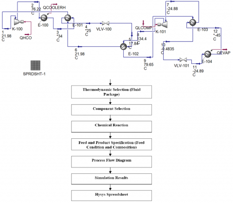
A simplified representation of a transcortical cascade system and flow diagram are depicted in Figure 1. The two single-stage refrigeration systems in the cascade refrigeration system are connected by a heat exchanger; the first uses NH3 (R717) for chilling in the HT cycle, while the second uses CO2 (R744) to condense NH3 in the LT cycle. Recycling the LT cycles by product heat increases the system's overall efficiency. After absorbing the heat QL from the cooling area (at temperature TE), the NH3 in the HT circuit evaporator is compressed by the NH3 compressor before condensing in the cascade heat exchanger. An expansion valve and an evaporator followed. When a CO2 gas cooler is placed in an LT circuit, its gliding temperature allows an external cooling medium to remove heat QH from the cooler. Cascade heat exchangers inflate the CO2 to vaporization pressure before evaporating it. Compressed carbon dioxide is delivered from the compressor to the gas chiller. Figure 2 and Figure 3 show the thermodynamic processes that happen along the P-h curve for CO2 and NH3, as well as their respective saturation lines.
The transcritical cascade system uses two refrigeration cycles that run on several refrigerants, including R717 (ammonia) and R744, to give both cooling and heating capabilities (carbon dioxide). The cascade structure enhances the performance of the entire system by facilitating effective heat transfer between the two cycles. While the R744 cycle operates at lower temperatures and is used for cooling, the R717 cycle operates at higher temperatures and is utilized for heating applications. Ammonia compressor with a large capacity and variable speed control to meet various cooling needs. Condenser that is air-cooled and has a lot of surface area to effectively disperse heat.
A thermostatic expansion valve (TXV), which regulates the flow of liquid ammonia into the evaporator, is known as an expansion valve. To cool the desired medium, use an evaporator with a shell and tubes. A compressor for high-pressure carbon dioxide with variable speed control. A cooler for gas to help heat escape during compression. A compressor to lower the CO2 pressure needed for the cooling cycle. A cooling application that makes use of a plate-type evaporator.
The thermodynamic state points and parameters of the carbon dioxide-ammonia (R744-R717) cascade system, including pressures, temperatures, and specific enthalpies, were calculated for the low-temperature (R744) and high-temperature (R717) refrigerants, respectively.
Table 2 can be used with any other high- or low-stage refrigerant; also, HYSES was applied with the data presented in Table 3 as input. Moreover, Figure 2 shows the P-h diagrams that indicate equivalent states in the system's saturated, superheated, and subcooled regimes.
Figure 1. Schematic of the system's components and flow diagram
Figure 2. Carbon dioxide and ammonia cycles on p–h property plot
Figure 3. Influence of TC on COP
Table 2. Determination of thermodynamic state points of R744-R717 cascade system by utilizing ASPEN HYSYS
|
Material Streams |
|||||
|
Name |
1 |
2 |
3 |
4 |
5 |
|
Molar Flow (kgmole/h) |
2.272 |
2.272 |
2.272 |
2.272 |
2.272 |
|
Mass Flow (kg/h) |
100 |
100 |
100 |
100 |
100 |
|
Liquid Volume Flow (m3/h) |
0.1212 |
0.1212 |
0.1212 |
0.1212 |
0.1212 |
|
Heat Flow (kJ/h) |
-9.046e+005 |
-9.018e+005 |
-9.173e+005 |
-9.201e+005 |
-9.201e+005 |
|
Name |
6 |
8 |
9 |
7 |
12 |
|
Molar Flow (kgmole/h) |
2.272 |
5.872 |
5.872 |
5.872 |
5.872 |
|
Mass Flow (kg/h) |
100 |
100 |
100 |
100 |
100 |
|
Liquid Volume Flow (m3/h) |
0.1212 |
0.1623 |
0.1623 |
0.1623 |
0.1623 |
|
Name |
10 |
11 |
|
|
|
|
Comp Mole Frac. (CO2) |
0.0000 |
0.0000 |
|
|
|
|
Comp Mole Frac. (NH3) |
1.0000 |
1.0000 |
|
|
|
|
Compositions |
|||||
|
Name |
1 |
2 |
3 |
4 |
5 |
|
Comp Mole Frac. (CO2) |
1.0 |
1.0 |
1.0 |
1.0 |
1.0 |
|
Comp Mole Frac. (NH3) |
0.0 |
0.0 |
0.0 |
0.0 |
0.0 |
|
Name |
6 |
8 |
9 |
7 |
12 |
|
Comp Mole Frac. (CO2) |
1.0 |
0.0 |
0.0 |
0.0 |
0.0 |
|
Comp Mole Frac. (NH3) |
0.0 |
1.0 |
1.0 |
1.0 |
1.0 |
|
Name |
10 |
11 |
|
|
|
|
Comp Mole Frac. (CO2) |
0.0000 |
0.0000 |
|
|
|
|
Comp Mole Frac. (NH3) |
1.0000 |
1.0000 |
|
|
|
|
Energy Streams |
|||||
|
Name |
QHCOMP |
QHCOOLER |
QLCOMP |
QEVAP |
|
|
Heat Flow (kJ/h) |
2804 |
1.549e+004 |
3.290e+004 |
2.021e+004 |
|
|
Unit Ops |
|||||
|
Operation Name |
Operation Type |
Feeds |
Products |
Ignored |
Calc. Level |
|
K-100 |
Compressor |
1 |
2 |
No |
500 |
|
QHCOMP |
|
||||
|
K-101 |
Compressor |
7 |
8 |
No |
500 |
|
QLCOMP |
|
||||
|
E-100 |
Cooler |
2 |
3 |
No |
500 |
|
|
QHCOOLER |
||||
|
E-104 |
Cooler |
11 |
12 |
No |
500 |
|
|
QEVAP |
||||
|
E-101 |
Heat Exchanger |
3 |
4 |
No |
500 |
|
6 |
1 |
||||
|
Unit Ops (Continued) |
|||||
|
Operation Name |
Operation Type |
Feeds |
Products |
Ignored |
Calc. Level |
|
E-102 |
Heat Exchanger |
5 |
6 |
No |
500 |
|
8 |
9 |
||||
|
E-103 |
Heat Exchanger |
12 |
7 |
No |
500 |
|
9 |
10 |
||||
|
VLV-100 |
Valve |
4 |
5 |
No |
500 |
|
VLV-101 |
Valve |
10 |
11 |
No |
500 |
|
SPRDSHT-1 |
Spread Sheet |
|
|
No |
500 |
Table 3. Input data were used by using a software package HYSES
|
Point |
1 |
2 |
3 |
4 |
5 |
6 |
7 |
8 |
9 |
10 |
11 |
12 |
|
Vapour Fraction (-) |
1 |
1 |
0 |
0 |
0 |
0.78 |
1 |
1 |
1 |
0 |
0.0823 |
0 |
|
Temp. (℃) |
21.98 |
76.22 |
34 |
25 |
17.84 |
17.84 |
-24.88 |
134.4 |
79.65 |
-48.35 |
-45 |
-45 |
|
Pressure (kPa) |
6000 |
12000 |
12000 |
12000 |
6000 |
6000 |
150 |
900 |
900 |
900 |
150 |
150 |
A parametric analysis of different gas cooler exits temperatures (32, 34, 36, 38, and 40 degrees Celsius) and evaporation temperatures (-25, -35, -40, -45, -50, and -55℃). The ideal condensing temperature of a cascade heat exchanger in a CO2-NH3 cascade refrigeration system is also determined for different cascade heat exchanger temperature differences (2, 4, and 6℃). To make the thermodynamic analysis simpler, the following premises are made:
The cascade heat exchanger outlet, HT cycle outlet, and LT cycle outlet evaporator have saturated refrigerants.
Irreversible adiabatic compression with 0.8 isentropic efficiency.
Negligible pressure and heat losses in the piping systems or system components.
Evaporators, gas coolers, and cascade heat exchangers transmit heat isobarically.
Evaporators, gas coolers, and cascade heat exchangers transmit little ambient heat.
The high-temperature evaporator receives all the heat that is rejected by the low-temperature condenser.
Mass and energy balances on every one of the system's components were performed during simulations of each refrigeration system using the ASPEN HYSYS software program. The refrigeration system was assumed to function in steady-state circumstances with low kinetic, pressure drops, and potential energy losses through the components of the system, as well as heat and friction losses. These assumptions formed the basis for the thermodynamic analysis of each system. The refrigeration system's performance coefficient is expressed as follows using the first law of thermodynamics.
Following are the compressor power requirements for the HT cycle:
$\dot{W}_{\text {comp } 1}=\dot{m}_{\mathrm{H}}\left(h_2-h_1\right)$ (1)
The HT gas cooler's heat transfer rate is expressed as follows:
$\dot{Q}_H=\dot{m}_H\left(h_2-h_3\right)$ (2)
The HT internal heat exchanger's energy balance results in:
$\left(h_1-h_6\right)=\left(h_3-h_4\right)$ (3)
Energy balance at the cascade condenser can be used to calculate the mass flow ratio:
$\dot{m}_{\mathrm{H}}\left(h_6-h_5\right)=\dot{m}_{\mathrm{L}}\left(h_8-h_9\right)$ (4)
The HT compressor's isentropic efficiency can be expressed as:
$\eta_c=\frac{\left(h_{2 s}-h_1\right)}{\left(h_2-h_1\right)}$ (5)
The following equation illustrates how effective the HT internal heat exchanger is:
$\varepsilon=\frac{\left(T_1-T_6\right)}{\left(T_3-T_6\right)}$ (6)
For the LT cycle, the compressor power consumption is provided by:
$\dot{W}_{\text {comp2 }}=\dot{m}_{\mathrm{L}}\left(h_8-h_7\right)$ (7)
The following factors determine how quickly the LT evaporator absorbs heat:
$\dot{Q}_{\mathrm{I}}=\dot{m}_{\mathrm{L}}\left(h_{12}-h_{11}\right)$ (8)
The internal heat exchanger in the LT has the following heat balance:
$\left(h_9-h_{10}\right)=\left(h_7-h_{12}\right)$ (9)
The LT propylene compressor's isentropic efficiency can be represented as follows:
$\eta_c=\frac{\left(h_{8 s}-\mathrm{h}_7\right)}{\left(\mathrm{h}_8-\mathrm{h}_7\right)}$ (10)
The following equation represents the LT internal heat exchanger's efficiency:
$\varepsilon=\frac{\left(T_7-T_{12}\right)}{\left(T_9-T_{12}\right)}$ (11)
The definitions of the cooling and heating COPs are as follows:
$\operatorname{COP}_{\mathrm{LT} \text { cooling }}=\frac{\dot{Q}_{\mathrm{L}}}{\dot{W}_{\text {comp2 }}} ; \operatorname{COP}_{\mathrm{HT} \text { cooling }}=\frac{\dot{Q}_{\mathrm{L}}}{\dot{W}_{\text {comp1 }}}$ (12)
The following equation represents the system's overall COP:
$\mathrm{COP}_{\text {sys }}=\frac{\dot{Q}_{\mathrm{L}}+\dot{Q}_{\mathrm{H}}}{\mathrm{W}_{\text {comp2 }}+\mathrm{W}_{\text {comp1 }}}$ (13)
Only particular enthalpy words can now be used to express the system's COP, as in:
$\begin{aligned} & \operatorname{COP}_{\text {sys }} =\frac{\left(h_6-h_5\right)\left(h_{12}-h_{11}\right)+\left(h_2-h_3\right)\left(h_{\mathrm{g}}-h_9\right)}{\left(h_8-h_7\right)\left(h_8-h_9\right)+\left(h_8-h_9\right)\left(h_2-h_1\right)}\end{aligned}$ (14)
where,
$\dot{Q}_{\mathrm{L}}$ and $\dot{Q}_{\mathrm{H}}$: The low and high temperature evaporators cooling loads in kW, respectively.
$\dot{W}$: The total power required by each system's fans, lighting, compressors, and other electrical components, expressed in kW. Therefore, in the current analysis, it has been assumed that the isentropic efficiencies of the LT and HT compressors are the same and constant. The aforementioned formulas provide the compressor power consumption for the HT cycle.
$\dot{m}_{\mathrm{H}}$: Mass flow rate of NH3 (kg/s)
$\dot{m}_{\mathrm{L}}$: Mass flow rate of CO2 (kg/s)
COP: The coefficient of performance
A cascade refrigeration system's key performance metrics include cooling, heating, and system COP. The ratio of the desired output (cooling or heating capacity) to the energy input, or COP, is a measure of a system's energy efficiency (power consumption). Better efficiency is indicated by higher COP values. As the evaporation temperature rises, the cooling coefficient of performance often declines. This is to be expected because cooling at higher evaporation temperatures causes the system to work harder. In a different way, the COP of R717 cycle rises with a higher evaporating temperature because it works better at higher temperatures just like it does in heating application. In the end, the COP of the system indicates the desirable zone of system operation, where heating and cooling processes are evenly balanced for maximal effectiveness. The heat transfer capacities of evaporator and the cooling/heating section of the system depend on the transfer rates of these two components. A system, which is more efficient in moving heat between refrigerant and the media being chilled or heated, has higher thermal conductivity. The evaporator and gas cooler are effective in transferring heat at a higher rate, due to the increased flow rate of the mass. This has been due to the higher heat transfer that can be achieved with the more flow rate of the refrigerant. The trade-off between achieving further gains in mass flow rate and the increased power consumption, bottlenecks, and other practical limitations would become apparent at some point. What emerges more clearly when evaluating the overall effectiveness of the cascade is the power consumption matter because it should be the aspect to be focused on. It immediately affects the system's running costs and environmental effects. As might be predicted, maintaining the necessary pressure ratios requires more power when the compressor is running at higher rates.
The simulations make use of isentropic compression and expansion processes as examples of perfect behavior components. The performance of the system as a whole is impacted by the losses and inefficiencies that are always present in various processes. The models ignore transient behavior during start-up, shutdown, or load variations and assume steady-state operation. For a more accurate portrayal, transient effects, which have the potential to drastically affect the system's performance, should be taken into account. the absence of heat losses to the environment, which is unrealistic. The efficiency of the system is impacted by heat losses from pipes, heat exchangers, and other components. In other conditions, the models account for the heat exchangers with single-phase flow while omitting the repercussions caused by the two-phase flow that are possible in some specific operating condition.
The refrigerants uncertainty analysis constitutes one of major factors that define the level of accuracy of simulation. Uncertainty and resultant error may be contributed to by the availability and quality of data, particularly for the newer refrigerants The fidelity of the component models utilized, for instance the compressor and heat exchanger models, is the link between the accuracy of the simulation and the model quality and complexity. Uncertainties in boundary conditions like inlet pressure and temperature of the entering fluid also affect the final results of the simulation.
The actual results might be different from the one of the simulated data due to the assumptions, constraints and uncertainties in the simulation. On comparing the output of the simulation with the results from the other authors it is essential to keep the following points in mind. This is a consequence of an additional complexity emerged when real applications are evaluated as well as the expected results of the simulations are treated with a skepticism. Results have a tendency to act as reference, but practical environment included many unforeseen real life situations that may affect the system performance. Observing variances of simulation outcomes, it is likely that there are some discrepancies between the expected and the literature background due to the model differences, component models, and the boundary conditions.
Subsequently, simulations are really helpful for system analysis and optimization notwithstanding the fact that they contain between assumptions and constraints. Solving these uncertainties and comparing the obtained results with experimental data and literature will certainly lead to a deep understanding of the behavior system, as well as the improved decision-making in practical applications. The future work of the research should focus on the enhancement of the model's accuracy through better property data, more detailed component models, and also experimental validation.
Besides that, APSEN HYSYS is used to determine the relationship between the temperature of the gas cooler exit (TC) the temperature of the evaporator exit (TE) and the temperature difference across cascade heat exchanger (DT). The COPmax for a given temperature range (TC, TE, and DT) means the maximum efficiency of the system at temperatures at a little above the freezing point. To start with, the outlet temperature of the gas cooler was stepped down from 32 degrees Celsius to 40 degrees Celsius as a first attempt. While other parameters, including TE=45 degrees Celsius, DT=2 degrees Celsius, and T5=17.84 degrees Celsius were held constant. Keeping the gas cooler outlet open allowed the evaporation temperature to be adjusted from 25℃ to 55℃.
All three temperatures TC=35℃, T5=17.84℃, and the temperature difference are kept constant. The temperature differential in the cascade condenser was then altered from 0℃ to 20℃ while maintaining the constants TC=35℃, TE=45℃, and T5=17.84℃. Finally, the waterfall is ceasing to flow. We were able to change the temperature (T5) from 25℃ to 0℃ while maintaining the same TC=35℃, TE=45℃, and DT=2℃.
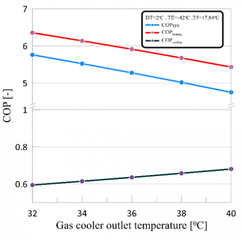
4.1 Effect of gas cooler exit temperature
The impact of the gas cooler output temperature TC on the overall COP, the COPheating, and the COPcooling is shown in Figure 3. The data reveal that as TC is increased, COPheating and COPsys both peak and subsequently decrease, whereas COPcooling does not change. When the gas cooler temperature rises, the pressure ratio across the HT circuit increases, requiring more work from the compressor. As a result, the overall amount of work done by the system rises, while the COP falls. Regardless of Tc, the cooling capacity of the system should remain constant in theory.
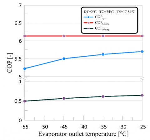
4.2 Effect of evaporation temperature
As shown in Figure 4, when the evaporating outlet temperature (TE) is raised, the system's overall COP and latent heat transfer coefficient (COPcooling) also rise, but the latent heat transfer coefficient (COPheating) does not change. As the temperature of the evaporator rises, the pressure ratio in the low-temperature circuit falls. As a result, the overall work done by the system's compressors is reduced, and the cooling capacity of the system is raised.
Figure 4. Influence of TE on COP
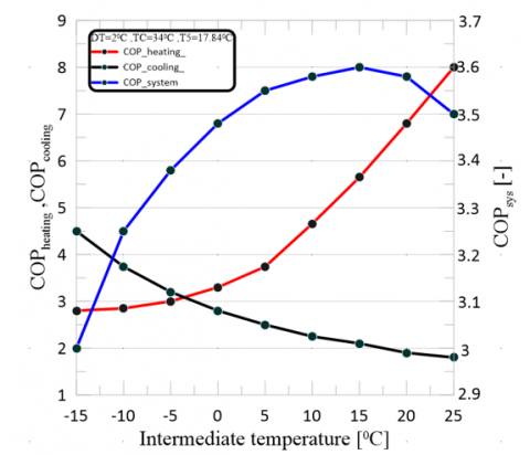
4.3 Effect of cascade heat exchanger temperature difference
Figure 5 shows that as T5 is raised, the coefficient of performance (COP) for heat transfer (COPheating) rises while the coefficient of performance for latent heat transfer (COPcooling) falls.
Figure 5. Variation of COP with intermediate temperature
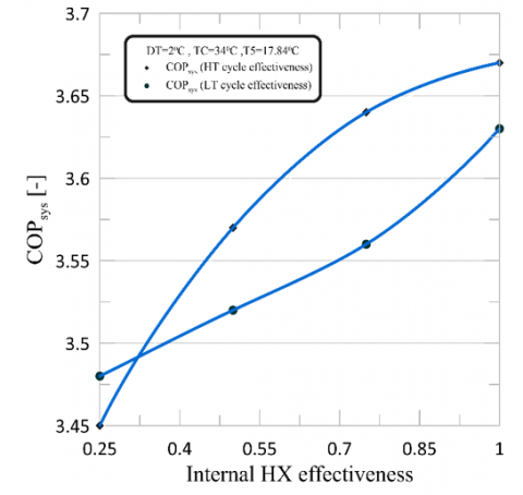
Figure 6. Variation COP system with effectiveness
As T5 increases, COPcooling decreases and COPheating improves because the temperature lift for the LT propylene cycle is greater than that for the HT carbon dioxide cycle. As a result of these two competing phenomena, systems with a maximum COP value see an early boost followed by a decline. These findings also imply that the organization will function at its best when the temperature in the middle of the facility is kept below 15.3 degrees Celsius. Figure 6 displays the influence of the efficiency of the HT and LT internal heat exchangers on the COPsys. While the internal heat exchanger in the HT circuit is more efficient than that in the LT circuit (1% vs. 0.5%), the net increase in system COP is small, making this solution inefficient. By improving the heat exchange between the cold and hot fluids, the IHX efficiency (e), which can be increased, can reduce the refrigeration capacity and LT compressor power input.
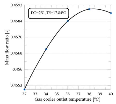
The influence of the temperature at the output of the gas cooler, denoted by TC, on the mass flow ratio, denoted by $\dot{m}_L / \dot{m}_H$, is depicted in Figure 7. The results demonstrate that $\dot{m}_L+\dot{m}_H$ initially increases, reaches a maximum value, and then begins declining with an increase in TC.
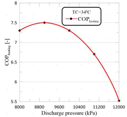
In Figure 8, we offer some predictions regarding the heating COP and the heating capacity. The coefficient of performance (COP) improved as the discharge pressure rose until a maximum was obtained at the pressure that was optimal for the discharge of the compressor. We were able to achieve a heating COP that was almost optimal with discharge pressures ranging from one hundred to one hundred twenty bars. Experiments conducted in the past by Kruse and Rüssmann [20], Getu and Bansal [12], and Dopazo and Fernández-Seara [21] largely support the conclusions drawn from these patterns.
Figure 7. Influence of TC on Mass flow ratio
Figure 8. Influence of pressure discharge on COP
Table 4. Quantitative results of the cooling/heating COPs
|
Evaporator Temperature on COP |
||||
|
State |
Temperature (℃) |
COP-System |
COP-Heating |
COP-Cooling |
|
Case 1 |
-25 |
5.566 |
6.136 |
0.64 |
|
Case 2 |
-35 |
5.545 |
6.136 |
0.63 |
|
Case 3 |
-45 |
5.535 |
6.136 |
0.636 |
|
Case 4 |
-55 |
5.522 |
6.136 |
0.624 |
|
State |
Pressure (kPa) |
COP-System |
COP-Heating |
COP-Cooling |
|
Case 1 |
8000 |
0.78 |
7.52 |
8.31 |
|
Case 2 |
9000 |
0.68 |
7.64 |
8.33 |
|
Case 3 |
10000 |
0.65 |
6.74 |
7.39 |
|
Case 4 |
11000 |
0.63 |
6.04 |
6.67 |
|
Case 5 |
12000 |
0.61 |
5.52 |
6.13 |
|
State |
Intermediate Temperature (℃) |
COP-System |
COP-Heating |
COP-Cooling |
|
Case 1 |
-15 |
3 |
2.8 |
4.5 |
|
Case 2 |
-10 |
3.25 |
2.85 |
3.74 |
|
Case 3 |
-5 |
3.38 |
3 |
3.2 |
|
Case 4 |
0 |
3.48 |
3.3 |
2.8 |
|
Case 5 |
5 |
3.55 |
3.74 |
2.5 |
|
Case 6 |
10 |
3.58 |
4.66 |
2.25 |
|
Case 7 |
15 |
3.6 |
5.65 |
2.1 |
|
Case 8 |
20 |
3.58 |
6.8 |
1.9 |
|
Case 9 |
25 |
3.5 |
8 |
1.8 |
The thermodynamic properties and performance traits of the refrigerants can be used to explain the trends in cooling, heating, and system COP with evaporation temperature (R717 and R744); see Table 4. The cooling coefficient of performance typically drops as the evaporation temperature rises. This is mostly due to the fact that a higher evaporation temperature causes the R744 cycle's compression ratio to increase, which adds to the compressor's workload. Besides, due to this fall in enthalpy between the evaporator and the gas cooler, the cooling capacity is also affected. Since then, it becomes problematic for a system to eradicate heat at the temperatures that are above the evaporation temperature. In the opposite direction, the temperature is rising as evaporation takes place, the heating COP absorbs more warmth. The bigger the enthalpy difference that exists between the gas cooler and the evaporator the more heating effect we get from the refrigeration cycle whilst operating at higher temperatures. R717 has compression ratio close to steady, which is responsible for increased efficiency of heating. Move the slider to the left or right to tape over the text The system's COP characteristic exhibits an optimal zone in operation where the heat and cooling processes are best matched. In this position, where the evaporating temperature is for about the middle values, the cooling COP is not substantially influenced, and the higher temperature operation of the R717 system provides the heating COP with more disclosure. The refrigerants could have its property like pressure, mass flow rate and the design of the heat exchanger could help to influence the heat transfer rates in the evaporator and the gas cooler. The evaporator and gas cooler being obvious is overall heat transfer rate increases with increase in mass flow rate. A greater heat transfer efficiency is achieved by higher mass flow rate, which in turn, allows for more chilled refrigerant flow thereby putting a high demand on heat exchangers. Besides, increasingly the thermoelectric heat exchangers cause the scaling up problem that can prevent the utilization of the flow rate increasing to high level. The thermal properties of the refrigerants and how compressor works are exploited during this explanation to predict the speed with which the power consumption depends on the speed of compressor. The compressor with its compression having to exert more effort to reach a greater pressure ratio is caused by the higher speeds; and, this leads to higher power usage.
Nevertheless, even high speed compressors may be accompanied by diminishing returns and the wastage of energy due to friction and other losses. The performance of the refrigerant depends on its thermodynamic features and the underlying compression and heat transfer power transmitting mechanism. For the purpose of achieving the highest system efficiency of the cascade system, it is imperative that you explore these thermodynamic justifications. By finetuning the system parameters in consideration with the thermodynamic principles, engineers can surmount the system's inefficiency and perform in the best way possible. Scientists and engineers will discover the areas for the improvement and develop the future prototypes in the field of heat and cold renewable energy technologies that are more efficient and sustainable as a result of them knowing the thermodynamics.
A refrigeration cascade prototype consisting of CO2 and NH3 was designed, built, and tested, as well as the cooling in stationary facilities as part of this contribution was done. In the case study analyzing the thermodynamic behavior of a CO2-NH3 transcritical cycle system was conducted. Concerning the system’s coefficient of performance (COP), the temperature of cascade heat exchanger, and the mass flow ratio for LT and HT cycles among the most important parameters to be experimented with are mentioned in the study. The parameters in question are the TE for affected water, the discharge pressure (DP) and the output temperature of the gas cooler (TC). The following assertions are supported by the results of the study: Attention has turned to the first ever use of the innovative refrigerant NH3 in a transcritical cascade refrigeration system.
(1) Liquid CO2 and NH3 transcritical cycle offer better efficiency than subcritical NH3 cascade cycles, which means they provide better system performance. A transcritical R717/R744 cascade system carries the flag as the most energy-efficient solution for applications that involve heating and cooling, with sustainability as the cherry on top. It adjusts on mass flow rates, power consumption and compressor speeds in order to maximize COP (coefficient of performance) but yet save power consumption. The system offers the benefits of both refrigerants, and its variables including mass flow rates and compressor speeds are simultaneously optimized. This approach can be used to develop more environmentally friendly cooling and heating solutions because it not only saves energy but also reduces the environmental impact thus helps reduce greenhouse gas emissions. This research provides valuable information that can be used to operate the system and design future ones, thus encouraging the application of energy-, resource-, and environment-friendly refrigeration systems in various industry and commerce sectors.
(2) A cascade heat exchanger connects two single-stage systems that employ NH3 (R717) for chilling in the HT cycle and CO2 (R744) to condense NH3 in the LT cycle to form the cascade refrigeration system. In order to increase system performance, the LT cycle's waste heat is also put to use for heating.
(3) The analysis of the thermodynamics of each system was conducted under the supposition that the refrigeration system operates under steady-state conditions, that pressure drops, the transfer of kinetic and potential energy through the system's components, as well as the loss of heat and friction, are all negligible.
(4) The system's coefficient of performance approaches 5.770 and 4.739, respectively, when the temperature rises from 32 to 40℃. The same is true for COP, which decreases as the gas cools.
(5) It can be noted that there is a positive relationship between gas cooler temperature and COP of cooling; at 32℃, COP of cooling is approximately 0.601, and at 40℃, COP of cooling is 0.680.
(6) That the system's COP remains constant while the evaporator's temperature changes. At -25℃ and -55℃, the system's COP reaches a value of 6.136. When the temperature of the evaporator changes, the results for COP of heating and COP of cooling are the same. The COP of heating is 5.522 at -25℃ and -55℃, whereas the COP of cooling is 0.6144.
(7) There is no doubt that the system's COP, heating, and cooling are all impacted by the rising discharge pressure. When the discharge pressure is 8000kPa, the system's coefficient of performance (COP) is 0.788; however, when the discharge pressure is increased to 12000kPa, the COP decreases to 0.614, indicating a negative correlation between the discharge pressure and the system's COP.
(8) It can be noted that there is a positive relationship between gas cooler temperature and COP of cooling; at 32℃, COP of cooling is approximately 0.5942, and at 40℃, COP of cooling is 0.6803.
In conclusion, the simulation results give important information on how the transcritical R717/R744 cascade system functions. The consideration of COP's corresponding with cooling, heating, and system coefficients finds the trade-off between the cooling and heating efficiency and puts a suggestion on the choice of the optimal operating conditions. Heat transfer rate and power consumption investigation prove crucial areas, where, ensuring for system efficiency, we will be able to go out with useful information to be considered in the system design and optimization. With different parameters the simulation of a plant suggests that the right balance of settings is necessary in order that performance and efficiency can be at their peak. With the transcritical cascade refrigeration applications being demonstrated through simulation results, these systems can now be designed to serve either the cooling or heating purposes.
The transcritical R717/R744 cascade system simulation and modelling can be enhanced in a number of ways, all of which will contribute to a more full and accurate representation of the system's behaviour in the future:
• Improve the precision of working models, such as, compression units, heat exchangers and evaporators. Include the departure effect from ideal behaviour and more complex thermodynamic models that will contribute to the correct representation of real-life performance.
• Conduct extensive laboratory experiments to support the confirmation of the simulation results. In order to enable direct comparison with the simulation, gather information on various system attributes and operating environments. This validation will raise confidence in the model's precision and point out any inconsistencies that require correction.
• Extend the simulation to handle transient operation, according to transient analysis. To comprehend the system's dynamic behaviour and control mechanisms, examine the system's response to start up, shutdown, and transient events.
• Utilize multi-objective optimization approaches to determine the ideal trade-off between power usage, cooling COP, heating COP, and other important performance indicators. Finding Pareto-optimal options for system design and operation will be aided by this method.
• Examine how the cascade system performs when using different refrigerants. Examine novel, low-GWP refrigerants to see if they can replace R717 and R744 and if they can adhere to changing environmental requirements.
• Heat Exchanger Design Optimization: Increase heat transfer rates while reducing pressure drops in the heat exchanger design. To increase total system efficiency, take into account cutting-edge geometries and materials.
• Implement cutting-edge control techniques to improve the system's performance in real-time. The system's functioning can be modified via dynamic control techniques in response to shifting external conditions and load requirements.
• Including More Advanced Thermodynamic Models: To enhance the precision of the refrigerant property data, think about incorporating more sophisticated thermodynamic models, such as equations of state and sophisticated mixing procedures.
• Analysis of Transient Heat Transfer Phenomena: In order to properly define the system reactions to dynamic load situations, analyzing the transient heat transfer radiation in the evaporator and the gas cooler is necessary.
• Energy storage technology integration as a measure to comprehensively enhance system effectiveness and load flexibility is another aspect that needs to be considered.
• Environmental analysis is the first step in determining the climatic consequence, conducting a life cycle assessment research covering the things like energy consumption, refrigerant leaking as well as manufacturing emissions.
The transcritical R717/R744 cascade simulation and modelling will be more reliable, accurate, and adaptable by considering these improvements, which will make decisions making easier during design and efficiency management of cooling and heating systems made up of natural gas that does not harm the environment.
|
1-6 |
refrigerant points (HT side) |
|
7-12 |
refrigerant points (LT side) |
|
COP |
coefficient of performance |
|
HT |
high temperature cycle |
|
IT |
intermediate temperature |
|
LT |
low temperature cycle |
|
$\dot{m}_{\mathrm{H}}$ |
flow rate of mass for CO2 |
|
$\dot{m}_{\mathrm{L}}$ |
propylene mass flow rate |
|
P |
pressure |
|
T |
temperature |
|
$\dot{W}_{\mathrm{HT}}$ |
HT power of compressor |
|
$\dot{W}_{\mathrm{LT}}$ |
LT power of compressor |
|
Greek symbols |
|
|
$\varepsilon$ |
internal heat exchanger effectiveness |
|
$\eta_c$ |
isentropic efficiency of compressor |
|
Subscripts |
|
|
max |
maximum |
|
sys |
system |
[1] Gholamian, E., Hanafizadeh, P., Ahmadi, P. (2018). Advanced exergy analysis of a carbon dioxide ammonia cascade refrigeration system. Applied Thermal Engineering, 137: 689-699. https://doi.org/10.1016/j.applthermaleng.2018.03.055
[2] Han, X., Li, J., Kong, X., Sun, T., Zhang, C., Yin, L. (2021). Thermodynamic performance study on a novel absorption‐compression cascade refrigeration activated by an internal combustion engine. International Journal of Energy Research, 45(6): 9595-9612. https://doi.org/10.1002/er.6484
[3] Ayub, A., Invernizzi, C.M., Di Marcoberardino, G., Iora, P., Manzolini, G. (2020). Carbon dioxide mixtures as working fluid for high-temperature heat recovery: A thermodynamic comparison with transcritical organic rankine cycles. Energies, 13(15): 4014. https://doi.org/10.3390/en13154014
[4] Zhang, Z., Liu, C., Chen, X., Zhang, C., Chen, J. (2017). Annual energy consumption of electric vehicle air conditioning in China. Applied Thermal Engineering, 125: 567-574. https://doi.org/10.1016/j.applthermaleng.2017.07.032
[5] Mohammadi, K., Powell, K.M. (2021). Thermoeconomic evaluation and optimization of using different environmentally friendly refrigerant pairs for a dual-evaporator cascade refrigeration system. Processes, 9(10): 1855. https://doi.org/10.3390/pr9101855
[6] Mosaffa, A.H., Farshi, L.G., Ferreira, C.I., Rosen, M.A. (2016). Exergoeconomic and environmental analyses of CO2/NH3 cascade refrigeration systems equipped with different types of flash tank intercoolers. Energy Conversion and Management, 117: 442-453. https://doi.org/10.1016/j.enconman.2016.03.053
[7] Nemati, A., Nami, H., Yari, M. (2017). A comparison of refrigerants in a two-stage ejector-expansion transcritical refrigeration cycle based on exergoeconomic and environmental analysis. International Journal of Refrigeration, 84: 139-150. https://doi.org/10.1016/j.ijrefrig.2017.09.002
[8] Aminyavari, M., Najafi, B., Shirazi, A., Rinaldi, F. (2014). Exergetic, economic and environmental (3E) analyses, and multi-objective optimization of a CO2/NH3 cascade refrigeration system. Applied Thermal Engineering, 65(1-2): 42-50. https://doi.org/10.1016/j.applthermaleng.2013.12.075
[9] Zhao, L., Cai, W., Ding, X., Chang, W. (2013). Model-based optimization for vapor compression refrigeration cycle. Energy, 55: 392-402. https://doi.org/10.1016/j.energy.2013.02.071
[10] Sun, Z., Wang, C., Liang, Y., Sun, H., Liu, S., Dai, B. (2020). Theoretical study on a novel CO2 Two-stage compression refrigeration system with parallel compression and solar absorption partial cascade refrigeration system. Energy Conversion and Management, 204: 112278. https://doi.org/10.1016/j.enconman.2019.112278
[11] Pan, M., Zhao, H., Liang, D., Zhu, Y., Liang, Y., Bao, G. (2020). A review of the cascade refrigeration system. Energies, 13(9): 2254. https://doi.org/10.3390/en13092254
[12] Getu, H.M., Bansal, P.K. (2008). Thermodynamic analysis of an R744-R717 cascade refrigeration system. International Journal of Refrigeration, 31(1): 45-54. https://doi.org/10.1016/j.ijrefrig.2007.06.014
[13] Chen, Y., Han, W., Jin, H. (2015). An absorption–compression refrigeration system driven by a mid-temperature heat source for low-temperature applications. Energy, 91: 215-225. https://doi.org/10.1016/j.energy.2015.08.046
[14] Sánchez, D., Cabello, R., Llopis, R., Catalán-Gil, J., Nebot-Andrés, L. (2019). Energy assessment and environmental impact analysis of an R134a/R744 cascade refrigeration plant upgraded with the low-GWP refrigerants R152a, R1234ze (E), propane (R290) and propylene (R1270). International Journal of Refrigeration, 104: 321-334. https://doi.org/10.1016/j.ijrefrig.2019.05.028
[15] Dubey, A.M., Kumar, S., Agrawal, G.D. (2014). Thermodynamic analysis of a transcritical CO2/propylene (R744-R1270) cascade system for cooling and heating applications. Energy Conversion and Management, 86: 774-783. https://doi.org/10.1016/j.enconman.2014.05.105
[16] Lee, T.S., Liu, C.H., Chen, T.W. (2006). Thermodynamic analysis of optimal condensing temperature of cascade-condenser in CO2/NH3 cascade refrigeration systems. International Journal of Refrigeration, 29(7): 1100-1108. https://doi.org/10.1016/j.ijrefrig.2006.03.003
[17] Kaushik, S.C., Kumar, P., Jain, S. (2002). Performance evaluation of irreversible cascaded refrigeration and heat pump cycles. Energy Conversion and Management, 43(17): 2405-2424. https://doi.org/10.1016/S0196-8904(01)00172-8
[18] Sarkar, J., Bhattacharyya, S., Lal, A. (2013). Performance comparison of natural refrigerants based cascade systems for ultra-low-temperature applications. International Journal of Sustainable Energy, 32(5): 406-420. https://doi.org/10.1080/14786451.2013.765426
[19] Hüsamettin, T.A.N., Erişen, A. (2022). Novel design and thermodynamic analyses of cascade refrigeration system at ultra-low temperature. International Journal of Thermodynamics, 1-9. https://doi.org/10.5541/ijot.1017282
[20] Kruse, H., Rüssmann, H. (2006). The natural fluid nitrous oxide-an option as substitute for low temperature synthetic refrigerants. International Journal of Refrigeration, 29(5): 799-806. https://doi.org/10.1016/j.ijrefrig.2005.11.007
[21] Dopazo, J.A., Fernández-Seara, J. (2011). Experimental evaluation of a cascade refrigeration system prototype with CO2 and NH3 for freezing process applications. International Journal of Refrigeration, 34(1): 257-267. https://doi.org/10.1016/j.ijrefrig.2010.07.010