Abdullah H.M. AlEssa![]() | Ahmed A. Hussien
| Ahmed A. Hussien![]() | Hamza Al-Tahaineh
| Hamza Al-Tahaineh![]() | Isam Qasem*
| Isam Qasem*![]() | Ayub Ahmed Janvekar
| Ayub Ahmed Janvekar![]()
© 2024 The authors. This article is published by IIETA and is licensed under the CC BY 4.0 license (http://creativecommons.org/licenses/by/4.0/).
OPEN ACCESS
Present study focuses on the better heat dissipation rate from horizontal rectangular fine integrated with longitudinal elliptic perforations. The process was carried out under natural convection and further compared to correspondent solid fin. The major parameters considered for the study was geometrical dimensions and thermal properties. The influence of the fin area was analyzed with respect to perforation and there by variation in the heat transfer was keenly noticed. A clear better result was noted for fin, when heat transfer data was monitored for the fin under considered range of elliptic diameters with equivalent solid fin. A direct proportional relation was made the amount heat transfer taking place with the fin thickness.
perforated fin, longitudinal elliptic perforation, finite element technique, heat dissipation, heat transfer enhancement
Heat removal process from the components is major challenge, since it leads to risk of damaging. If the heat removal rate is slow or inadequate, overheating is another issue which directly influence the behavior of the working component. Hence the popular field called thermal engineering was getting popularity and leads to control and improvements in thermal system/components for better heat circulation. The popular key parameters used control the heat movement include heat transfer coefficient (surface to surrounding) and projected area to perform the heat interaction. Fins are been consider as the best candidate for the faster heat transfer since the surface area is large. Thus, this a good choice to directly attached such features to hot surface where cooling is needed almost [1, 2].
Fins can be considered as sheet like components, whose thickens and materials are varied in different dimensions based on the applications. Some of the applications are found in heat exchangers, boilers, industries burners, nuclear reactors, electric transformers, power plants and so on [3]. The fins shapes and designs have been studied for managing thermal performance, to meet heat transfer removal requirements, in the past decades. Commonly, Researchers uses a plate, triangular, and annular fin [4], but many other types of fins have been investigated such as tree-shaped fins (Y- shaped fins and T-shaped fins) [5, 6], uneven tree-like fins [7], gradient fins [8] with different fin number [9], fin layout [10], and fin materials [11].
This cooling technology has been developed due the huge demands to make products lightweight, compact, and economical [12]. Overall machining cost to get the marketable product for the fin based on the efficiency plays vital role, which need to be considered before the actual production or the design of the fin [13, 14]. Previous research work has given snipped outline on various methods adopted in fin design by making changes in the fin structure. Some of the design mainly focused on the getting cavities are periphery, generating holes, small slots in the junctions, providing groves and channels. Thus, the intension was to get more and more surface area [15-17].
Perforated plates also know was fins are the best way to representing surface interruption. One way is block reduction, which can enhance the performance of heat dissipation from most thermal applications such as novel heat exchanger for better colling rates, film cooling to enhance heat transfer, energy storage application, and solar collectors for under heat exchange [18]. Chin et al. [19] utilized perforated pin fin on investigating the heat dissipation of heat sink. They studied the effect of number and size of perforated region in each pin on forced convective heat transfer numerically and experimentally. Their results performed high enhancement Nusselt number reached to 48% comparing with solid fins when number of perforating increases. In addition, the pressure drop became lower. Li et al. [20] worked on the triangular perforated fin by focusing on the synergy with respect to fluid flow. Intension was to consider convective heat transfer. They concluded the perforated fins caused additional flows and vortices. Further, this phenomenon can be enhancing the heat transfer performance. Maji et al. [21] found improvement on heat transfer when they studied the performance of different configurations of perforated fin heat sink. Sundar et al. [22] investigated numerically the heat-dissipation performance of heat sinks using a staggered array of perforated fins. They studied the effect of fins porosity and angle of orientation. Their results showed 7-12% enhancement on heat resistance comparing with non-perforating fins. Maiti and Prasad [23] designed and analyzed a novel perforated pin fins numerically. In addition, performance was checked for forced type of heat transfer from the fin and heat sink. A detailed comparison was made at Reynolds number varying 2000 -11000, between perforated fins and solid pin fins. Outcome the research work led to the conclusion that perforated fins have performed way better than conventional way of design in terms of both heat transfer coefficient and pressure drop.
A turbulency flow happened due perforated fins is more usefulness than surface area in enhancing heat transfer coefficient. This phenomenon may increase the heat transfer coefficient immensely comparing with flat fins [24, 25]. On other side, perforated fins make an interruption of developing thermal boundary layers after each removing areas which also increasing heat transfer coefficient. Therefore, the shape and number of perforated fins is very important factors can control the heat dissipated rate [26].
Ibrahim et al. [27] investigated the effect of different shapes of perforated fins (rectangular, circular and triangular) on performance of heat exchanger. They compared the results with non-perforated fins. There results show significant enhancement on forced convection heat transfer of perforated fins over flat fins. The maximum enhancement was for the circular perforation which it was 51.29%. They pointed also; wider perforation area could develop the intensity of turbulence. Sudheer et al. [28] studied a performance of circular perforated fins numerically. They showed a significant decrease in temperature comparing with non-perforated fins. They studied the role of perforation array and diameter on the temperature profile of fines. They revealed that increasing perforated diameter caused higher reduction of fins temperature.
The above literature mainly concerned about the effect of perforated fins on forced convection heat transfer where there is a lack of the research introduce a relation of perforated fins with natural convection heat transfer. Consequently, the study of surface coefficients is needed. The surface coefficients of perforated fins can be estimated by studying the shape geometry of the perforated fins (augmentation ratio and open area ratio). The main aim of this research is to investigate the effects of the geometry parameters of vertical longitudinal elliptic perforation on enhancing natural heat transfer rate of the fins. In addition, focus was given on the geometric values impact on the heat transfer rate. The study made a successful attempt to come up with optimum elliptic perforation size for enhanced heat transfer in a horizontal flat plate. The fin with optimum elliptic perforation introduces a good solution in cooling the electric devices with light weight and little cost of fins.
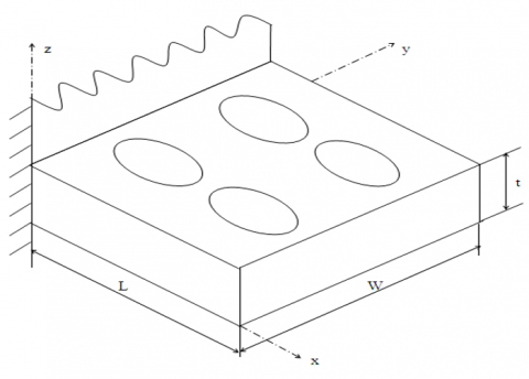
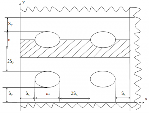
The perforated fin with longitudinal elliptic perforations and the symmetrical parts considered in analysis the heat transfer rate in this study is shown in Figures 1 and 2, respectively.
The considered part the in a transverse or so called lateral was used with Biot number in z and y directions (Biz) and (Biy), can be predicted by Eqs. (1) and (2), respectively:
$B i_z=h_{p s} . t / 2 k$ (1)
$B i_y=h_{p s} \cdot\left(S_y+n / 2\right) / k$ (2)
where, k indicates thermal conductivity, t refers to thickness of the fin along z-direction. While Sy indicates half vertical distance between the perforated areas, and n is the semi minor axis of the ellipse, as shown in Figures 1 and 2.
Figure 1. Fin structure indicating longitudinal elliptic perforations
Figure 2. Actual hatchet part used in heat transfer analysis with longitudinal elliptic perforations
The value of Biot number indicates the effects of conjugated heat transfer, which are indicated as Biz and Biy along z and y direction respectively. The value of these variable is very small i.e., less than 0.01, therefore the conjugated heat transfer in z and y directions is also come down to small values. Further its temperature gradient in respective directions can be neglected [17, 29]. In presented work, the values of Biz and Biy are having smaller value (0.01). This possible reason for this can be due to the heat transfer and the temperature gradient, which was assumed to be 1-D along x direction. To perform various analysis, some of the assumptions were made where, process of heat transfer was steady as well it is with one-dimensional mode. Thermal conductivity was maintained uniformly, with focus to homogeneity as well as isotropic across the fin material, both base and surrounding temperatures were considered to be uniform, absolute area measured for Side region was much lowered as compared to surface area (w >>t) and weather its perforated or solid the value of heat transfer coefficient remains unchanged.
With acceptant of considered assumptions energy equation can be implied for fin as stated below [30]:
$k \frac{d^2 T}{\mathrm{dx}^2}=0$ (3)
For this general expression the boundary conditions imposed as below.
1. For the fin at base location (x=0):
$T=T_b$ (4)
2. In case of perforated surfaces:
$k \frac{\mathrm{dT}}{\mathrm{dx}} l_x+h_{\mathrm{ps}}\left(T-T_{\infty}\right)+h_{\mathrm{pc}}\left(T-T_{\infty}\right)=0$ (5)
According to the fin with longitudinal elliptic perforations that shown in Figure 1, the surface area of this fin including the tip can be expressed as:
$\begin{aligned} & A_{\mathrm{pf}}=\left(2 \mathrm{~W} * L-2 \mathrm{~N}_c * A_c\right)+(W * t)+\left(N_c * A_{\mathrm{pc}}\right) \\ & =A_f+N_c\left(A_{\mathrm{pc}}-2 \mathrm{~A}_c\right) \\ & \left.=A_f+N_x * N_y * \pi \mathrm{D}(t-\mathrm{D} / 2)\right)\end{aligned}$ (6)
A concept of weight reduction ratio RWF was used to show the relation between perforated vs non perforated fin. The relation is given below.
$\begin{aligned} & \mathrm{RWF}=W_{\mathrm{pf}} / \mathrm{W}_{\mathrm{sf}} \\ & =\left(L * W * t-N_x * N_y * A_c * t\right) /(L * W * t) \\ & =1-\left(N_x * N_y * A_c * t\right) /(L * W * t) \\ & =1-\pi \mathrm{D}^2 /\left(4\left(2 \mathrm{~S}_x+D\right)\left(2 \mathrm{~S}_y+D\right)\right.\end{aligned}$ (7)
The number of longitudinal elliptic holes Nx and Ny, must be integers, hence following expressions are used to get the final values used based on perforated fin for a considered length and width.
$N_x=\operatorname{Int}\left(\mathrm{L} /\left(2 \mathrm{~S}_x+D\right)\right)$ (8)
$N_y=\operatorname{Int}\left(\mathrm{W} /\left(2 \mathrm{~S}_y+D\right)\right.$ (9)
In the above relation the word “Int” implies to integer number function.
There are many popular techniques to get solution for the energy Eq. (1), based on the present boundary condition it was solved numerically by enabling finite-element technique to get best results. The computer program for one-dimensional problems, the subroutines called heat 1, adjust. decomp, and solve are used for the solution of this problem [30]. The next set of variational statement are as shown below [30]:
$\begin{aligned} & I_n=\frac{1}{2} \iiint_V k\left(\frac{\mathrm{dT}}{\mathrm{dx}}\right)^2 \mathrm{dV}+\frac{1}{2} \iint_{A_{\mathrm{ps}}} h_{\mathrm{ps}}\left(T-T_{\infty}\right)^2 \mathrm{dA}_{\mathrm{ps}}+ \\ & \frac{1}{2} \iint_{A_{\mathrm{pc}}} h_{\mathrm{pc}}\left(T-T_{\infty}\right)^2 \mathrm{dA}_{\mathrm{pc}}+\iint_{A_t} h_t\left(T_t-T_{\infty}\right) T \mathrm{dA}_t\end{aligned}$ (10)
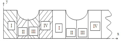
The basis for computing the considered heat transfer situation with the boundary conditions can be referred from Figures 2 to 4.
Note: I, IV: - Straight (Uniform) Region II, III: - Tapered Regions
Figure 3. All four regions are indicated with symmetricity for perforated fin
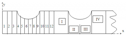
Figure 4. Symmetrical part for the considered four regions
With the help of Figure 2 with hatching indicates the symmetry part, while Figures 3 and 4 try to give more information to the four regions. Four regions are numbered as 1, 2, 3 and 4. This was marinated across all the considered perforation. A careful view leads to conclusion that regions 1 and 4 are uniform in nature, while 2 and 3 are more or less tapered in shape in the forward and then in backward directions, respectively.
The regions 1 and 4 are split into Nf elements for each case. While the regions 2 and 3 are classified as Nt elements each. The values of Nf and Ntare based on the mesh distribution. The expression to related, total number of elements Ne with total number of nodes Nn is as shown below.
$N_e=N_x\left(2 \mathrm{~N}_f+2 \mathrm{~N}_t\right)$ (11)
$N_n=N_e+1$ (12)
The problem is solved based on the variational approach with the concept of symmetric banded matrix width. The algebraic system obtained is solved by using the Choleski decomposition method as described by Rao [30]. Most of the variable remains same in case of heat dissipation from a fin, solid or perforated. The critical parameters need to focus are fin surface area and heat transfer coefficient. In case of solid fin, both features are recognized. The average value of hss is that for a single horizontal plate under natural convection mode can be represented below [31]:
$h_{\mathrm{ss}}=\mathrm{Nu} . \mathrm{k}_{\mathrm{air}} / \mathrm{L}_c$ (13)
$L_c=\mathrm{L}^* \mathrm{~W} /(2 \mathrm{~L}+2 \mathrm{~W})$ (14)
Nusselt number average was noted as Nu [31]:
$\mathrm{Nu}=\left(\mathrm{Nu}_u+\mathrm{Nu}_l\right) / 2$ (15)
$\begin{gathered}\mathrm{Nu}_u=\left[\left(1.4 / \ln \left(1+1.4 /\left(0.43 \mathrm{Ra}^{0.25}\right)\right)\right)^{10}\right. \left.+\left(0.14 \mathrm{Ra}^{0.333}\right)^{10}\right]^{0.1}\end{gathered}$ (16)
$\mathrm{Nu}_l=\frac{0.527 \mathrm{Ra}^{0.2}}{1+(1.9 / \mathrm{Pr})^{0.9} 2 / 9}$ (17)
In present work fin tip was considered as vertical surface for which the Nusselt number, Nut are calculated as is given below [31], this was applied for both perforated and non-perforated type of fin.
$\mathrm{Nu}_t=0.5\left(\left(\frac{2.8}{\ln \left(1+\frac{2.8}{0.515 * \mathrm{Ra}^{0.25}}\right)}\right)^6+\left(0.103 * \mathrm{Ra}^{0.333}\right)^6\right)^{(1 / 6)}$ (18)
$h_t=\mathrm{Nu}_t \cdot \mathrm{k}_{\mathrm{air}} / \mathrm{L}_c$ (19)
$L_c=L \cdot t /(2 L+2 t)$ (20)
As far as discussion are considered for fin with respect to surface was covered in previous section. Now important can be given for three distinct heat transfer coefficients. Firstly, heat transfer coefficient for the solid portion in case of perforated surfaces (hss) can be determined using the below equation [12]:
$h_{\mathrm{ps}}=(1+0.75 \mathrm{ROA}) \cdot \mathrm{h}_{\mathrm{ss}}$ (21)
Next, when it comes to with perforation, we donate it as hpc. Thereby Nusselt number (Nuc) can be represented using below equation [1]:
$\mathrm{Nu}_c=\left[\left(\mathrm{Ra}_c / 16\right)^{-1.03}+\left(0.62 \mathrm{Ra}_c^{0.25}\right)^{-1.03}\right]^{-(1 / 1.03)}$ (22)
Finally, the last expression was related to the heat transfer coefficient at fin tip, which was denoted by ht. For this case Nusselt number (Nut) was given by Eq. (19). Since variation in temperature using perforated fin was occurred the length i.e., x direction. Now, the value of heat dissipation rate from the perforated fin was denoted as Qpf, and is determined using below expression.
$\begin{gathered}Q_{\mathrm{pf}}=2 \mathrm{~N}_y \cdot \sum_{I=1}^{N_e}\left(\frac{T_I+T_{I+1}}{2}-\right. \left.T_{\infty}\right)\left(h_{\mathrm{ps}}\left(\frac{P(I)+P(I+1)}{2}\right) \operatorname{Le}(I)+h_{\mathrm{pc}} \cdot \mathrm{L}_{\mathrm{pc}}(I) \cdot \mathrm{t}\right)+Q_t\end{gathered}$ (23)
where, Qt is the heat dissipation from the tip of the perforated fin, which can be reported with the below expression.
$Q_t=A_t * h_t *\left(T_t-T_{\infty}\right)$ (24)
In case to compare performance of the perforated fin with that of the solid (non-perforated) one of the same dimensions, the following equations are used [32].
$\frac{T_x-\mathrm{T}_{\infty}}{T_b-T_{\infty}}=\frac{\operatorname{Cosh}(\mathrm{m}(L-x))+\left(\frac{h_t}{m * \mathrm{k}}\right) \operatorname{Sinh}(\mathrm{m}(\mathrm{L}-\mathrm{x}))}{\left.\operatorname{Cosh}(m * \mathrm{~L})+\left(h_t /(m * k)\right) \operatorname{Sinh}(m * \mathrm{~L})\right)}$ (25)
$T_{\mathrm{sf}}=T_{\infty}+\frac{T_b-T_{\infty}}{\operatorname{Cosh}(\mathrm{m} * L)+\left(\frac{h_t}{m * k}\right) \operatorname{Sinh}(m * L)}$ (26)
$Q_{\mathrm{sf}}=k * A * m\left(T_b-T_{\infty}\right) \frac{\operatorname{Sinh}(m * L)+\left(\frac{h_t}{m * k}\right) \operatorname{Cosh}(m * L)}{\operatorname{Cosh}(m * L)+\left(\frac{h_t}{m * k}\right) \operatorname{Sinh}(m * L)}$ (27)
$\begin{gathered}m=\sqrt{\frac{h * P_{\mathrm{sf}}}{k * A}}, P_{\mathrm{sf}}=2 . \mathrm{W}, A=W * \mathrm{t}, A_{\mathrm{sf}} =L * P_{\mathrm{sf}}+W * t\end{gathered}$ (28)
The relation between heat dissipation with respect to the perforated fin was given with RQF, as shown below:
$\mathrm{RQF}=Q_{\mathrm{pf}} / \mathrm{Q}_{\mathrm{sf}}$ (29)
One of the optimum to show improvement across relation of perforated fin with solid counterpart is by make a comparative study. In other words, heat transfer behavior can be notices across the considered boundary conditions. Now, to define the boundary condition both fins are kept at same dimensions. The dimension was fin length of L=50 mm while width as 100 mm. In addition, thermal conductivity was also maintained with constant value. Next, constant base and ambient temperatures, $T_b$ and $T_{\infty}$ of 100 0C and 20 0C was also taken care. The above values are chosen as a practical value which can be applied in electric devices to be cooled. The objectives of the current numerical investigation were to provide temperature variation throughout the fins, heat dissipation enhancement in the perforated fin, the optimum dimensions of elliptic perforation, and the fin weight reduction.
4.1 Temperature distribution
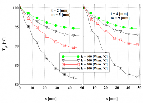
The temperature variation was a prime aspect of the study, where in continuous values of temperature was noted across perforated fin. Temperature values T_"pf" (x), was observed with respect to perforation parameters as well as fin thickness. The generated plot is as shown in Figure 5. For this analysis perforation spacing was kept Sx=Sy=1mm. In simple words the temperature variation along the fin gives better understanding about fin performance. If the temperature values for fin are high then the efficiency percentage will improve along with better effectiveness. Another technical parameter was thermal resistance, here higher fin temperatures was notices with fin having low thermal resistance.
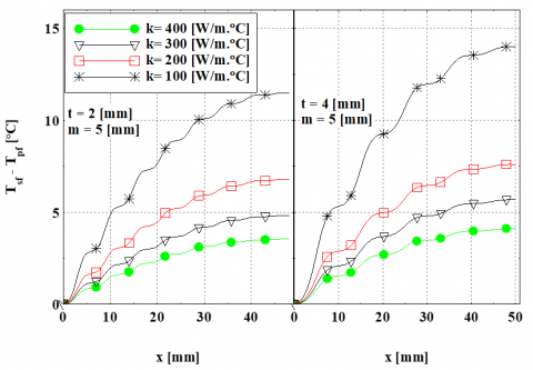
There is direct relation of sectional area with the fin thermal resistance, any variation cross section with respect to the length shall impact on the fin thermal resistance. If the value of thermal conductivity was mad high, it was noted that the thermal resistance was getting lower for the considered sectional area of the perforated fin. This behavior can be seen via the cure, which is smoother in nature. To get better understanding of temperature difference distribution of the solid fin, a plot was made by varying (Tsf(x)-Tpf(x)). This information is as shown in Figure 6.
The plot makes it clear that in every considered value, the temperatures along the solid (non-perforated) fin are higher than those with respect to the perforated one. This is due to the reason that the perforated fin has thermal conduction resistance which was greater than the non-perforated one. The difference (Tsf-Tpf) reduces as thermal conductivity rises. Figures 5-6 demonstrate that as the longitudinal elliptic perforation diameter was increased, the temperature difference, or temperature drop across the fin base and tip, increases. The main possible reason for the increase in thermal resistance of the perforated fin as the longitudinal elliptic was due to increase in the perforation diameter. Therefore, as long as a temperature variation is kept under consideration, it is a good practice to use small perforation dimensions. Fin thickness is another parameter which will directly proportional to the temperature distribution. With help of all the plots it can be seen that thermal resistance of the perforated fin decreases with respect to higher fin thickness. This information makes it evident that from the temperature distribution viewpoint that, by using large fin thicknesses can be more beneficial.
Figure 5. Temperature variation for considered perforated fin length
Figure 6. Temperature variation along the perforated fin length with respect to fin thickness and diameter
4.2 Ratio of heat dissipation rate
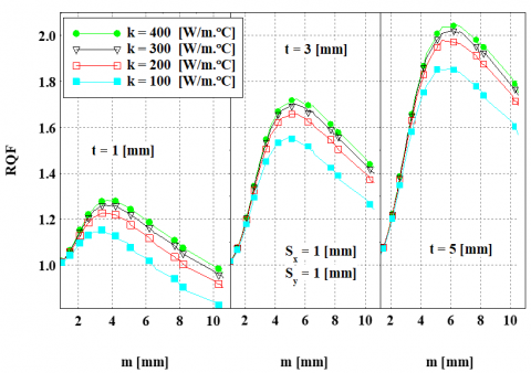
The parameter called ratio of heat dissipation rate (RQF) was used to relate between perforation dimensions (m and n) with considered fin thickness. With the help of Figure 7, it can be noted that the larger amount of surface area achieved due to the thicker fin made the overall heat transfer to carry out at faster rate. Hence the enhancement noticed was more at any value of (m and n).
Figure 7. Indicating RQF values with respect to perforation (hole) diameter
A smooth trend line of continuous increase values was noticed with RQF when plotted m at various t. The plot can be seen in Figure 7. This variation followed a consistent trend of higher values reaching to max tip then followed by a decrease trend. This trend can be justified by the total impact of changing in fin heat transfer (due to surface area) and heat transfer coefficients impacted based on perforations.
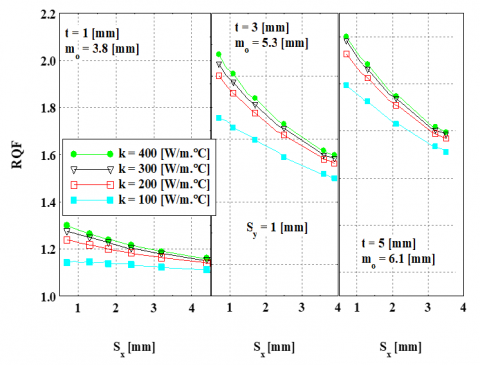
Furthermore, another relation can be conveyed that RQF was found to be the function of the perforation dimension (m). When perforation dimension at which RQF ratio has a peak location can be indicated as optimum perforation diameter (mo). With the help of Figure 7. The optimum dimension (mo) can be showed as a function based on fin thickness. The approximate values of (mo) can also be generated using the same Figure 7. The impact of longitudinal spacing (Sx) plays a key role for the fin performance. Thereby, the heat dissipation ratio (RQF) was taken into consideration as a function of Sx. This was represented as shown in Figure 8. The increasing in fin heat dissipation due to perforation is interpreted by the increasing in heat transfer coefficients of the perforated surfaces of the fin.
Figure 8. Variation of RQF with longitudinal spacing
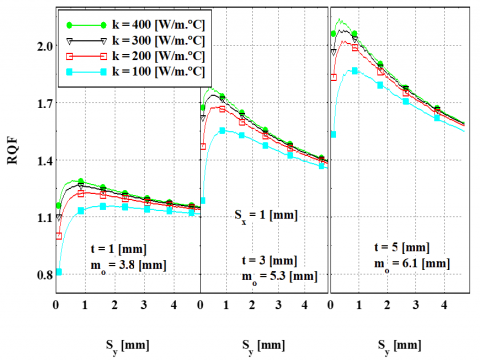
This figure indicates that at any t, the (RQF) decreases with increasing of spacing (Sx). With the help of Figure 8, the behavior trend of increasing values of Sx was getting smaller with number of holes considered. The variation indicates the loss of the element, which causes heat transfer enhancement due to holes. Thus, as per the Sx parameter spacing can be considered to lower the such possibilities. Next, the behavior of lateral spacing (Sy) on the perforated fin performance can be considered by generating the data of RQF as a function of Sy. This can be done for low and high thermal conductivities as shown in Figure 9.
Figure 9. Variation of RQF with lateral spacing
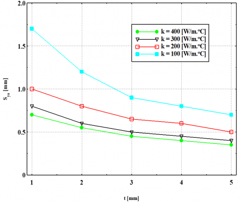
An up and down movement of RQF was noticed with Figure 9, initially there is upward movement with low values of Sy, then decline was noticed thereby. The possible reason for this path due to the fin thermal resistance as well as exposed surface area. Next, Figure 8 indicates the major dependency of the spacing Sy, with respect to RQF. The relation exists between RQF and optimum perforation diameter (Do). These are related to the function of spacing Sy. From the Figure 9, the behavior of RQF gets higher value and then tends to dip as the spacing Sy values increases. By considering the snipped overview it can be noticed that there is an optimum value for the spacing Sy, was can be noted as Syo. The values of Syo are mainly influenced by fin thickness as well as thermal conductivity. With the help of Figure 10, approximate values of Syo are indicated.
Figure 10. Variations of Syo with respect to t
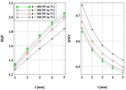
Generated Figure 10 makes clear relation with Syo with respect to t, decreases of Syo was related to increases t. To get better understanding of heat flow, data for perforated fin at the optimum values of perforation geometry were also populated. Further the ratios of heat dissipation (RQF) and weight reduction (RWF) are noted as a depended variable with respect to fin thickness. Next, fin thermal conductivity at the optimum perforation diameter (mo) as well as optimum lateral spacing (Syo) as shown in Figure 11.
Figure 11. Relation of ratio of heat dissipation rate (RQF) as well as ratio of reduction weight (RWF) with respect to fin thickness
With the help of Figure 10, it can be noticed that usage of perforations in fins leads to better flow of heat dissipation. Further this will also help in reducing the fin weight. It can be deduced that better results were reported with by increase in fin thickness and thus rise of thermal conductivity. This means that the using of perforated fin leads can improve heat dissipation rates and at the same time leads to decrease the expenditure of fin material.
Present works reports the behavior of longitudinal Elliptic Perforations fin and its surface parameters on natural heat convection to dissipate the excess heat from light electrical devices. Intensive applications of perforation fins are found in heat exchangers, boilers, industries burners, nuclear reactors, electric transformers and power plants. The methodology used was numerically approach with finite element method for one- dimensional model. At specific values of the perforated geometry, the temperature gradient between the plate and solid fins was less than the temperature drops along the perforated fin. The rate at which heat was dissipated using perforated fins depends on the thickness of the fins, the thermophysical characteristics of the fin materials, and the surface characteristics of the perforated area. The main surface parameters could impact mainly on the heat dissipation rate in elliptical perforated areas are perforation diameter (Do) and optimum spacing (Syo). In contrast, the highest heat transfer rate achieved by using these parameters ideal values. The perforation of fins increases heat dissipation rates while at the same time reducing the material consumption of the fins. This work can further be elaborated by considering 3-D approach and other perforated geometries.
|
A |
Fin cross sectional area |
|
Bi |
Biot no. |
|
D |
Longitudinal Elliptic perforation diameter |
|
h |
Coefficient of heat transfer |
|
k |
Thermal conductivity |
|
L |
Longitudinal distance |
|
N |
Longitudinal elliptic perforations number |
|
Nu |
Nusselt no. |
|
OA |
Total open area of elliptic perforations |
|
Q |
Rate of rejected heat from the fin |
|
Ra |
Rayleigh no. |
|
ROA |
Ratio of total open area of elliptic perforations |
|
RQF |
Rejected heat rate of perforated fin to that of solid one |
|
RWF |
Weight of the perforated fin to that of solid one. |
|
S |
Distance between two adjacent perforations |
|
T |
Temperature |
|
t |
Fin thickness |
|
W |
Fin width or fin weight |
|
Subscripts |
|
|
b |
Base of fin support surface |
|
c |
Area of removal surface |
|
l |
Fin lower surface |
|
pc |
Perforation internal liner area |
|
pf |
Perforated fin |
|
sf |
Original non-perforated fin |
|
ss |
Non-perforated area |
|
t |
Fin-tip |
|
u |
Fin upper area |
|
x |
x-axis |
|
y |
y-axis |
|
z |
z-axis |
|
$\infty$ |
Ambient |
[1] Haghighi, S.S., Goshayeshi, H.R., Safaei, M.R. (2018). Natural convection heat transfer enhancement in new designs of plate-fin based heat sinks. International Journal of Heat and Mass Transfer, 125: 640-647. https://doi.org/10.1016/j.ijheatmasstransfer.2018.04.122
[2] Mousa, M.G. (2013). Thermal performance of pin–fin heat sink subject in magnetic field inside rectangular channels. Experimental Thermal and Fluid Science, 44: 138-146. https://doi.org/10.1016/j.expthermflusci.2012.06.006
[3] Rath, S., Siddhartha, Dash, S.K. (2022). Thermal performance of a radial heat sink with longitudinal wavy fins for electronic cooling applications under natural convection. Journal of Thermal Analysis and Calorimetry, 147: 9119-9137. https://doi.org/10.1007/s10973-021-11162-x
[4] Abdulateef, A.M., Mat, S., Sopian, K., Abdulateef, J., Gitan, A.A. (2017). Experimental and computational study of melting phase-change material in a triplex tube heat exchanger with longitudinal/triangular fins. Solar Energy, 155: 142-153. https://doi.org/10.1016/j.solener.2017.06.024
[5] Khan, Z.H., Khan, W.A., Hamid, M. (2021). Non-Newtonian fluid flow around a Y-shaped fin embedded in a square cavity. Journal of Thermal Analysis and Calorimetry, 143(1): 573-585. https://doi.org/10.1007/s10973-019-09201-9
[6] Bejan, A., Almogbel, M. (2000). Constructal T-shaped fins. International Journal of Heat and Mass Transfer, 43(12): 2101-2115. https://doi.org/10.1016/S0017-9310(99)00283-5
[7] Liu, X., Huang, Y., Zhang, X., Zhang, C., Zhou, B. (2020). Investigation on charging enhancement of a latent thermal energy storage device with uneven tree-like fins. Applied Thermal Engineering, 179: 115749. https://doi.org/10.1016/j.applthermaleng.2020.115749
[8] Yu, C., Zhang, X., Chen, X., Zhang, C., Chen, Y. (2020). Melting performance enhancement of a latent heat storage unit using gradient fins. International Journal of Heat and Mass Transfer, 150: 119330. https://doi.org/10.1016/j.ijheatmasstransfer.2020.119330
[9] Biwole, P.H., Groulx, D., Souayfane, F., Chiu, T. (2018). Influence of fin size and distribution on solid-liquid phase change in a rectangular enclosure. International Journal of Thermal Sciences, 124: 433-446. https://doi.org/10.1016/j.ijthermalsci.2017.10.038
[10] Yuan, Y., Cao, X., Xiang, B., Du, Y. (2016). Effect of installation angle of fins on melting characteristics of annular unit for latent heat thermal energy storage. Solar Energy, 136: 365-378. https://doi.org/10.1016/j.solener.2016.07.014
[11] Hajmohammadi, M.R., Ahmadian, M., Nourazar, S.S. (2019). Introducing highly conductive materials into a fin for heat transfer enhancement. International Journal of Mechanical Sciences, 150: 420-426. https://doi.org/10.1016/j.ijmecsci.2018.10.048
[12] Al-Essa, A.H., Al-Hussien, F.M. (2004). The effect of orientation of square perforations on the heat transfer enhancement from a fin subjected to natural convection. Heat and Mass Transfer, 40(6-7): 509-515. https://doi.org/10.1007/s00231-003-0450-z
[13] Chung, B.T.F., Iyer, J.R. (1993). Optimum design of longitudinal rectangular fins and cylindrical spines with variable heat transfer coefficient. Heat Transfer Engineering, 14(1): 31-42. https://doi.org/10.1080/01457639308939792
[14] Li, H., Hu, C., He, Y., Tang, D., Wang, K., Huang, W. (2021). Effect of perforated fins on the heat-transfer performance of vertical shell-and-tube latent heat energy storage unit. Journal of Energy Storage, 39: 102647. https://doi.org/10.1016/j.est.2021.102647
[15] Al-Essa, A.H., Alrawashdeh, K.A.B., Okour, M.H., Talat, N.T. (2018). Improvement of free convection heat transfer from a fin by longitudinal hexagonal perforations. Journal of Heat and Mass Transfer, 15(2): 457-481. http://doi.org/10.17654/HM015020457
[16] AlEssa, A.H. (2021). Heat dissipation analysis of a fin with hexagonal perforations of its one side parallel to the fin base. Yanbu Journal of Engineering and Science, 7(1): 21-30.
[17] Al-Essa, A.H. (2012). Augmentation of heat transfer of a fin by rectangular perforations with aspect ratio of three. International Journal of Mechanics and Applications, 2(1): 7-11. https://doi.org/10.5923/j.mechanics.20120201.02
[18] Jang, D., Kim, D.R., Lee, K.S. (2015). Correlation of cross-cut cylindrical heat sink to improve the orientation effect of LED light bulbs. International Journal of Heat and Mass Transfer, 84: 821-826. https://doi.org/10.1016/j.ijheatmasstransfer.2015.01.081
[19] Chin, S.B., Foo, J.J., Lai, Y.L., Yong, T.K.K. (2013). Forced convective heat transfer enhancement with perforated pin fins. Heat and Mass Transfer, 49: 1447-1458. https://doi.org/10.1007/s00231-013-1186-z
[20] Li, J., Ling, X., Peng, H. (2013). Field synergy analysis on convective heat transfer and fluid flow of a novel triangular perforated fin. International Journal of Heat and Mass Transfer, 64: 526-535.
[21] Maji, A., Bhanja, D., Patowari, P.K. (2017). Numerical investigation on heat transfer enhancement of heat sink using perforated pin fins with inline and staggered arrangement. Applied Thermal Engineering, 125: 596-616. https://doi.org/10.1016/j.applthermaleng.2017.07.053
[22] Sundar, S., Song, G., Zahir, M.Z., Jayakumar, J.S., Yook, S.J. (2019). Performance investigation of radial heat sink with circular base and perforated staggered fins. International Journal of Heat and Mass Transfer, 143: 118526. https://doi.org/10.1016/j.ijheatmasstransfer.2019.118526
[23] Maiti, A., Prasad, S. (2017). Alternative heat sink to enhance thermo-hydraulic behavior of an array of short pin fins. In Proceedings of the 3rd World Congress on Mechanical, Chemical, and Material Engineering (MCM'17), Rome, Italy. https://doi.org/10.11159/htff17.121
[24] Karabacak, R., Yakar, G. (2011). Forced convection heat transfer and pressure drop for a horizontal cylinder with vertically attached imperforate and perforated circular fins. Energy Conversion and Management, 52(8-9): 2785-2793. https://doi.org/10.1016/j.enconman.2011.02.017
[25] Tahrour, F., Ahmad, H., Ameur, H., Saeed, T., Abu-Zinadah, H., Menni, Y. (2023). 3D numerical study and comparison of thermal-flow performance of various annular finned-tube designs. Journal of Ocean Engineering and Science, 8(3): 294-307. https://doi.org/10.1016/j.joes.2022.02.009
[26] Jassem, R.R. (2013). Effect the form of perforation on the heat transfer in the perforated fins. Academic Research International, 4(3): 198.
[27] Ibrahim, T.K., Mohammed, M.N., Mohammed, M.K., Najafi, G., Sidik, N.A.C., Basrawi, F., Hoseini, S.S. (2018). Experimental study on the effect of perforations shapes on vertical heated fins performance under forced convection heat transfer. International Journal of Heat and Mass Transfer, 118: 832-846. https://doi.org/10.1016/j.ijheatmasstransfer.2017.11.047
[28] Sudheer, M., Shetty, A., Somayaji, S. (2015). Finite element investigations of temperature distribution in fins with circular perforations. American Journal of Materials Science, 5(3C): 157-161. https://doi.org/10.5923/c.materials.201502.31
[29] Hajmohammadi, M.R., Rasouli, E., Elmi, M.A. (2020). Geometric optimization of a highly conductive insert intruding an annular fin. International Journal of Heat and Mass Transfer, 146: 118910. https://doi.org/10.1016/j.ijheatmasstransfer.2019.118910
[30] Rao, S.S. (2013). The Finite Element Method in Engineering: Pergamon International Library of Science, Technology, Engineering and Social Studies. Elsevier.
[31] Raithby, G.D., Hollands, K.G.T. (1975). A general method of obtaining approximate solutions to laminar and turbulent free convection problems. In Advances in Heat Transfer, 11: 265-315. https://doi.org/10.1016/S0065-2717(08)70076-5
[32] Incropera, F.P., Witt, D.P.D. (1990). Fundamentals of Heat and Mass Transfer. J. Wiley.