Vechalapu Kamaraju*![]() | Chintapalli V.V.S. Bhaskara Reddy
| Chintapalli V.V.S. Bhaskara Reddy![]()
© 2024 The authors. This article is published by IIETA and is licensed under the CC BY 4.0 license (http://creativecommons.org/licenses/by/4.0/).
OPEN ACCESS
In this study, we modeled and designed a novel, efficient controller for a hybrid renewable energy system with an integrated converter and associated grid interface. The proposed grid-interfaced Hybrid Renewable Energy System (HRES) model is built by properly connecting the photovoltaic (PV) system, Wind Energy Conversion System (WECS), battery, DC/DC converter, Maximum Power Point Tracking (MPPT) controller, microgrid, and load to obtain the desired output. The integrated converter used in this is a modified high-conversion ratio converter for improving conversion efficiency. A maximum power point tracker is used to track the maximum power from renewable energy sources. We have designed an efficient controller with a successful control strategy to provide optimal switching for the grid-side inverter to achieve optimal energy management in the system. A novel control method is developed by combining the Adaptive Grasshopper Optimization Algorithm (AGOA) and the Gradient Boosting Decision Tree Algorithm (GBDT), which is named the AGOA-GBDT method. The proposed approach uses AGOA as an evaluation technique to develop accurate command signals and enrich the command signal database for offline use. The data sets collected from the sensors are also used to build a control system with fast feedback for online training of the GBDT system. The main purpose of using and proposing this novel control technique is to improve efficiency by achieving optimal energy management in the model. The formulation of the problem considers several constraints, such as the intermittent nature of renewable energy sources, the state of charge of the storage components, and the power demand. The MATLAB/Simulink platform simulates the proposed system model with the proposed controller and other controllers. This proposed control technique proved to be the best in efficacy and convergence properties when compared with other existing control techniques in the literature.
photovoltaic system, Wind Energy Conversion System, hybrid renewable energy systems, optimal energy management, microgrid, converter, Maximum Power Point Tracking, controller
As conventional energy consumption continues to decrease, environmentally friendly renewable energy sources (RES) are becoming more important due to their compatibility and efficiency compared to conventional power plants [1]. Renewable energy is widely recognized as an excellent solution to combat climate change, protect the environment, and provide clean and sustainable energy for future generations [2]. The most promising electrical energy produced comes from solar and wind energy [3]. A solar energy system and a wind energy conversion system are integrated to create a more powerful and cost-effective HRES. HRES has received much attention in the past decade [4]. The development of microgrids has the potential to meet the energy needs of cities, businesses, and other hard-to-reach or off-grid locations [5]. DC systems are recommended over AC systems due to their compatibility with modern DC loads, supercapacitors, and batteries [6]. When the RES produces more energy than it needs, the excess energy is stored in an energy storage device called a "Battery Bank" (BB). In bad weather, the battery bank provides stored energy as backup [7]. These are charged with large amounts of energy during off-peak hours, usually during the day, and used to generate electricity during peak hours [8]. The Maximum PowerPoint Tracker (MPPT) sends precise command signals to the PWM unit so that the duty ratio of the switches in the converter remains the same and optimal switching is done to keep conversion losses to a minimum [9]. We adopted the SCB converter and used it in this proposed model after a few modifications, naming it the MHCR converter [10, 11]. To increase the efficiency of the model, we should reduce the switching loss by implementing optimal switching for the converter. To obtain optimal switching, one must design an optimal controller. In this, we designed an intelligent controller by combining AGOA [12, 13] and GBDT [14, 15], which is called the AGOA-GBDT method. The hunting activities of grasshoppers served as inspiration for the AGOA algorithm. Using the AGOA control method, the gain of the PI controller was optimized. The gradient-boosting decision tree algorithm (GBDT) is a way of using machine learning to deal with classification and regression problems. It uses a compromised base series of classified data to build robust models, typically decision trees. The effectiveness of the proposed controller is compared with other recent strategies such as AGOA [12, 13] and GWOA [16, 17], as well as the MATLAB/Simulink system.
The remaining work is described below: Section 2 describes the brief review on recent research work, research gaps in literature, motivation for the research work, objectives of research work, and contributions to research work. Section 3 describes the system configuration of the grid-interfaced HRE system connected to the suggested controller and the modeling of all devices used in this model. The control structure and implementation of the suggested strategy are described in Section 4. The results of the simulation and the conversation are demonstrated in Section 5. The manuscript was concluded in Section 6.
Many works are available in the literature based on managing energy in RES with different controllers and control strategies. A literature review of current publications explores how to handle energy in grid-connected HRES systems. The energy management system consists of photovoltaic and wind generators, as well as grids and batteries to store energy. In energy management, it is very difficult to operate wind systems without an MPPT controller to track the maximum energy from photovoltaics. Likewise, it is very difficult to manage energy in a battery system without a charge controller. It monitors and controls the energy sources of RES and its power converters. It mostly depends on many factors related to the problem. Volatility arising from renewable resources and load requirements is the result of complex interactions between factors.
2.1 Identification of research gaps
In this section, we discuss the major research gaps and shortcomings of some works in the literature to the best of our knowledge.
• Padhmanabhaiyappan et al. [14] found that an EFO-GBDT approach with a built-in converter can help grid-connected microgrids reach robust optimal utilization. The EFO method shows accuracy, but the main drawback is that it takes more execution time than the proposed control method.
• Kamaraju et al. [17] presented that WECS would find a solution by designing a GWOA-based controller for energy management. The advantages of GWOA are that it initiates a specific control signal for the controller, but the main drawback is that the performance level is low and the execution time is high. This function is limited to a single energy source and is not combined with other energy sources to improve system efficiency and robust utilization.
• Premkumar et al. [18] presented different topologies of inverters used in renewable energy systems, but the main shortcoming is that they only focus on the different topologies used to get the maximum efficiency from the PV system and the use of any controller to provide optimal switching. not an inverter to obtain maximum energy from a PV system.
• Somarin and Parvari [19] came up with a hybrid AWO-ANFIS method for optimal utilization of linked RES in microgrids. The advantage of AWOA is that it has the population-based ability to avoid local optimal solutions and obtain the global optimal solution. The main drawback is that it is not good at exploring the search space. The main benefits of ANFIS for HRES depend on how well the energy is managed to get the best results. On the other hand, defects have a lot of fuzzy logic that is difficult to understand with probability theory and conditions.
• Xu et al. [20] described a continuous supply of electricity to isolated islands from HRES in 2021. The main drawback of this work is that it is limited to off-grid use and uses a fuzzy controller for optimization. It is a good control method, but computationally, more effort is needed to design the rule base.
2.2 Motivation behind the research
Normally, it has numerous control techniques that are utilized in HRE systems for energy administration approaches like GWOA, AWOA [21, 22], EFO, the ANFIS, Fuzzy, and so on. The hardest parts of this research are making sure that the power supply matches the power demand in different weather conditions and enhancing the utilization of power at the consumer end by using an efficient controller with a good control approach. Even though many researchers have been focusing on the development of energy management in the microgrid, they have not found optimal solutions, and their research has several drawbacks. The shortcomings of existing work motivate me to conduct research.
2.3 Research objectives
The main goal of this research is to improve the efficiency of the system by finding the best way to manage energy in a proposed HRE system that is connected to the grid. Only optimal switching of the converters allows for optimal energy management. In the proposed system model, power converters are used to transfer power from the source to the load, and an innovative controller with a good control approach is also required to provide optimal switching to these converters. The objective function of the system is to minimize system losses by providing optimal switching to the converters and to maximize power availability at the consumer end.
$f(x)=\underbrace{\min }_{x_1, x_2 \ldots x_n}\left\{\begin{array}{l}P_D-\left(P_{G S W}+P_{S B G}\right) \text { when } P_D>P_{G S W} \\ P_D-\left(P_{G S W}-P_{S B G}\right) \text { when } P_D<P_{S B G}\end{array}\right.$ (1)
where, $P_{G S W}=P_{P V}+P_{\text {Wind }}$ is power generation from solar and wind energy, $P_{S B G}=P_{\text {Battery }}+P_{\text {Grid }}$ is power supplied from battery and grid, $P_D$ is power demand, $x_1, x_2 \ldots x_n$ are control variables. In the above Eq. (1), it says that if the renewable energy sources cannot meet demand at peak load because of bad weather, the battery is drained and the grid supplies power to load up to meet demand. The battery will charge to capacity if the power consumption is less than the power generation, and any excess power will be transferred to the grid via net metering.
2.4 Contributions of the research work
In this paper, we have made a few contributions to fill the research gap and overcome the shortcomings of some works, which are discussed.
• Model and design of grid-interfaced HRE systems, considering solar and wind energy systems.
• In this work, the concepts of batteries and microgrids are also considered. To optimize the switching of the converter, an MPPT controller is also included. for optimal switching of DC/DC converters.
• Proposed a modified topology called the MHCR converter with a higher conversion ratio, lower switching loss, and reduced voltage stress. The proposed dc/dc converter was modeled using the state-space averaging method and voltage transfer gain expression in terms of duty ratio.
• Proposed an efficient controller with an effective control technique, i.e., AGOA-GBDT, to provide optimal switching in the grid-side inverter.
The configuration of grid-connected HRES is presented in Figure 1. The proposed system includes renewable energy sources such as solar and wind. A system model is designed to combine HRES, batteries, converters, controllers, and loads. A solar PV system generates electrical energy from light energy and supplies energy to the DC bus through a DC/DC converter. Wind energy is converted into mechanical energy by wind turbines. As a result, it is implied that the wind that blows through the turbine blades turns at an angle, creating mechanical torque and, subsequently, mechanical energy. Because they are mechanically linked, the rotor of a wind turbine and the rotor of a permanent magnet synchronous generator rotate at the same speed. The PMSG then produces fluctuating, three-phase electrical power. A 3-phase diode rectifier converts three-phase pulsating alternating current power into pulsating direct current power. A DC/DC converter converts pulsing DC to steady DC based on the required voltage. The MPPT controller controls the switching period of the converter by taking the voltage and current results as reference values. The battery bank is connected to the DC bus through a bidirectional converter. When energy demand is low, the battery powers up. It discharges when the power demand is high. To power an AC load, a 3-level IGBT inverter transfers the power from DC to AC.
Figure 1. System configuration of grid-interfaced HRES with proposed controller
Modeling comes before everything else in the design of a grid-interfaced HRES. The load share of the PV system is considered while doing the modeling. The required mechanical output is considered when modeling a wind turbine. The required electrical energy generation must be considered while modeling the PMSG. The converter is designed to give us the required output voltage. In order to switch the converter as best as possible, the controller is simulated. It increases the efficiency of the system through ideal switching.
3.1 Modelling of the photovoltaic cell
In Eq. (2), we can see how to figure out how much power a PV cell puts out:
$P_{o u t}=V_{p v} \times I_{p v}$ (2)
This is made up of solar panels that may be linked in series, parallel, or both ways. The Eq. (3) below gives the PV system's power output:
$P_{p v_{-} o u t}=P_{p v_{\text {_rated }}} \times\left(\frac{G}{G_{\text {ref }}}\right) \times\left[1-K_T\left(T_C-T_{\text {ref }}\right)\right]$ (3)
The temperature of the solar radiation in terms of ambient temperature is shown in Eq. (4):
$T_c=T_{a m b}+(0.0256 \times G)$ (4)
where, $P_{p v_{-} o u t}$ is the power generated by the $\mathrm{PV}$ system, $P_{p v_{-} rated}$ is the rated PV power, $G$ is the solar radiation, $G_{r e f}$ is the reference solar radiation $\left(G_{r e f}=1000 \mathrm{~W} / \mathrm{m}^2\right), K_T$ is the temperature coefficient $K_T=-3.7 \times 10^{-3}{ }^{\circ} \mathrm{C}, T_{r e f}$ is the reference temperature $\left(T_{r e f}=25^{\circ} \mathrm{C}\right)$, and $Tc$ is the nominal temperature, $T_{a m b}$ is the ambient temperature.
3.2 Modelling of the wind turbine
Wind turbines convert the kinetic energy of the wind into mechanical energy. The components of a wind turbine are rotor blades, yaw mechanism, electronic controller, hub, high-speed shaft with mechanical brake, gearbox, low-speed shaft, hydraulics system, tower, anemometer, wind turbine, and cooling unit. WT can rotate on either a vertical or horizontal axis. The output power and torque of wind turbines are shown in Eqs. (5)-(6):
$P_{\text {mech }}=\frac{1}{2} \times a_{\text {density }} \times B_C(\mu, \delta) \times\left(\frac{R_b \times \omega_{\text {ors }}}{\lambda_{\text {ots }}}\right)^3$ (5)
$T_{\text {mech }}=\frac{1}{2} \times a_{\text {density }} \times B_C(\mu, \delta) \times \omega_{\text {ors }}{ }^2 \times\left(\frac{R_b}{\lambda_{\text {ots }}}\right)^3$ (6)
where, $a_{\text {density }}$ is the air density, $B_c(\mu, \delta)$ is the Betz constant, $R_b$ is the Radius of the turbine blades, in theory, up to 59 percent of wind power extracted, according to Betz, optimum rotor speed is denoted as $\omega_{\text {ors }}, \lambda_{\text {ots }}$ is represented as optimum tip speed ratio.
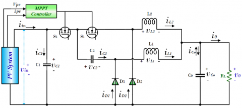
3.3 Modelling of the MHCR DC-DC converter
Interleaved Buck Converters (IBC) are used in many industrial and high-power applications. The interleaved method makes the converter more dynamic and reduces the need for filters at the input and output. When high-voltage transfer is required, IBCs suffer from very low duty ratios. Additionally, a specific control strategy is required to balance the two inductor currents. Kim et al. [11] developed a SC-HCR converter to overcome the shortcomings of conventional SCB. We have made a few modifications to the converter and used it in this proposed system model, which we named the MHCR converter. A recommended converter is shown in Figure 2. The voltages of the inductors may be used to compute the voltage transfer gain for the recommended converter, as shown in Eq. (8):
$\left(V_{\text {in }}-V_{\text {out }}\right) d_2 T_s=V_{\text {out }}\left(d_1-1\right) T_s$ (7)
$V_{T g}=\frac{V_{\text {out }}}{V_{\text {in }}}=\frac{d_2}{\left(d_1+d_2\right)-1}$ (8)
If the both the pulse widths assumed to be same then $d_1=d_2=d$ then the voltage transfer gain will be represented as in the Eq. (9).
$V_{T g}=\frac{V_{\text {out }}}{V_{\text {in }}}=\frac{d}{2 d-1}$ (9)
Figure 2. Circuit diagram of a modified HCR converter
To make the system more efficient by optimally managing power, you need an efficient controller with effective control techniques. In this work, we have proposed an AGOA-GBDT based controller to achieve optimal power management and high system efficiency. In the design process, modelling is a foundational task. Here, the main objective of the controller is to minimize the error by tuning the gains of the PI controller.
Figure 3. Control structure of the proposed controller
The control structure is shown in the Figure 3: At first the controller senses the three-phase voltage $\left(V_{a b c}\right)$ and threephase current $\left(I_{a b c}\right)$ from the grid, and then it transforms those values into $\alpha \beta$-frame by using Park's transformation. After that, it again transforms into the two-phase synchronous reference frame ($d q$-frame) by using Clark's transformation. A phase locked loop is used to keep the d-q rotating reference frame and the three-phase frame in sync with each other. Eqs. from (10)-(12) are representing the controller objective functions.
$I_{d \_ \text {error }}=I_d^*-I_d ; I_{q \_e r r o r}=I_q^*-I_q$ (10)
$E_d=\left(K_p+\frac{K_i}{s}\right) I_{d_{-} \text {error }} ; E_q=\left(K_p+\frac{K_i}{s}\right) I_{q_{-} \text {error }}$ (11)
$v_d^*=v_d+\left(E_d+\omega L I_q\right) ; v_q^*=v_q+\left(E_d-\omega L I_d\right)$ (12)
Here $I_d, I_q$ are the active and reactive components of current; similarly, $V_d, V_q$ are the active and reactive components of voltage.
4.1 Implementation of proposed control strategy
The AGOA and GBDT algorithms are combined to form a proposed control system, known as the AGOA-GBDT technique. In line with the power management between the generation unit and the consumer, AGOA implements an analysis technique to set specific control signals in the proposed system and improve the control signal directory for offline use. A data set that has already been collected is also used to train the GBDT system online, which speeds up the installation of the control system. In addition, system data that are subject to equality and inequality constraints describe an objective function.
4.2 Adaptive grasshopper optimization algorithm
AGOA is a popular population-based metaheuristic method for solving various engineering problems. A notable and promising GOA variant is AGOA. However, GOA has several drawbacks, such as the lack of flexibility in set parameter values and dynamic contexts. To overcome those drawbacks, you need to adopt a few parameters. AGOA is programmed by adopting parameters in GOA. When control parameter values must vary throughout the stochastic search process or when their initial values are unknown, self-adaptation techniques are commonly used. The control parameter in AGOA is self-adaptive. Below is a step-by-step description of how the algorithm creates an ideal dataset.
Step 1: Initialization
In this step, initialize the population of parameters used to tune the controller gains.
Step 2: Generation at Random
The start-up step serves as the basis for the random behaviour of gain settings. The illogical solutions are obtained from the following Eq. (13):
$Z_i=\left[\begin{array}{cccc}K_p^{11} K_i^{11} & K_p^{12} K_i^{12} & \cdots & K_p^{1 n} K_i^{1 n} \\ K_p^{21} K_i^{21} & K_p^{22} K_i^{22} & \cdots & K_p^{2 n} K_i^{2 n} \\ \vdots & \vdots & \cdots & \vdots \\ K_p^{m 1} K_i^{m 1} & K_p^{m 2} K_i^{m 2} & \cdots & K_p^{m n} K_i^{m n}\end{array}\right]$ (13)
Step 3: Fitness
The fitness of the population is determined by the grasshoppers' location. The following equation contains the necessary fitness function as shown in Eq. (14):
$U=\min \{e(t)\}$ (14)
where, U is the fitness function, e(t) is the error signal in time domine.
Step 4: Position Upgrading
For the optimum solution, one must upgrade the position of grasshoppers based on individual fitness, which is updated based on the value of the fitness after every individual fitness value calculation.
Step 5: Crossover and Mutation
The two individuals mix, and as the mutation process goes on, the two are changed randomly based on how fit they are. The crossover and mutation are calculated using the following formulas shown in Eq. (15).
Crossover $=\frac{\alpha_{g c}}{d_c} ;$ Mutation $=\frac{\beta_{g c}}{d_c}$ (15)
where, $\alpha_{g c}$ is the number of gene crossover, $d_c$ is the distance between the grasshoppers, $\beta_{g c}$ is the point of mutation. Utilizing the updated movement, determine and evaluate fitness.
Step 6: Termination
Check the situation to see if it needs to be stopped. If it is not, move on to step 3; if it is, stop looking. The optimal tuning of gain parameters will minimize the error in the controller to achieve the best HRES utilization.
4.3 Gradient boosting decision tree
Gradient boosting is a machine learning method used to solve classification and regression issues. Its ensembles transform a weak base series of categorized models into stronger ones, often decision trees. This machine learning methodology differs significantly from conventional boosting methods since it uses positive and negative weight samples. The GBDT follows the path of the negative gradient to achieve global convergence of the algorithm. Consider the $\left(x_j, y_j\right)_{j=1}^n$ optimum dataset produced by the AGOA. The gradient decent algorithm in this case ensures the convergence of the GBDT. Where $x_j$ is number of generated pulses, and $y_j$ is generated labels. The convergence process of the method is described in detail below.
Step 1: In the first step, the constant value of the model is shown by the following Eq. (16).
$H(x)=\arg \min \sum_{j=1}^n L\left(y_j, \beta\right)$ (16)
Step 2: The gradient direction in each residual is determined using the following Eq. (17).
$y_j^*=-\left[\frac{\partial L\left(y_j, H\left(x_j\right)\right)}{\partial H\left(x_j\right)}\right]_{H(x)-H_{m-1}(x)}, j=\{1,2,3 \ldots n\}$ (17)
where, m is the number of iterations.
Step 3: The basic classifier is used to fit the data sample to the first model after it has been built. The model's acquired parameter $a_m$ is fitted using the least squares method in the model $f\left(x_j, a_m\right)$ as in the Eq. (18).
$a_m=\arg \min \sum_{j=1}^n\left[y_i^*-\beta f\left(x_i, a\right)\right]^2$ (18)
Step 4: The loss function is minimized. The likelihood of the current sample weight depends on Eq. (19) below:
$\beta_m=\arg \min \sum_{j=1}^n L\left\{y_i, H_{m-1}(x)+\beta f\left(x_i, a\right)\right\}$ (19)
Step 5: The following Eq. (20) represents how the model is updated:
$H_m(x)=H_{m-1}(x)+\beta_m f\left(x_i, a\right)$ (20)
The GBDT is trained in the best way possible, produces the best results, and has the same level of classification accuracy based on fitness function. On the MATLAB/Simulink framework, the simulation results of the proposed hybrid system with the proposed control system are assessed. The next section contains them. The proposed control technique flow chart is as shown in Figure 4.
Figure 4. Flow chart of AGOA-GBDT algorithm
This section explains how to get the most out of the HRE system by using the recommended AGOA-GBDT control system that has been run on the MATLAB/Simulink framework to get the best energy management in the model. In different situations, the proposed system model and control method are tested to see how well they work and how they compare to other control strategies that already exist.
Case 1: Changing of PV irradiance and wind speed under constant load
Case 1 represents the examination of the HRES model under changing PV irradiance and wind speed. Figure 5(a) represents the change in PV irradiance; we initially assumed that the PV irradiance was 1000 W/m2, and it was stable for 0.3 seconds. After that, it will reduce linearly to 800 W/m2. It is continued for another 0.5 seconds, and again, it is decreased to 400 W/m2. Again, it is increased to 800 W/m2 at 0.7 seconds, and after that, it is increased to 1000 W/m2. Figure 5(b) represents a variable wind speed of around 12 km/h.
Figure 6 shows how energy sources share the load and compares the power outputs of systems that use a proposed control method, AGOA-GBDT, to existing control methods, such as AGOA and GWOA, in Case 1. Figure 6(a) shows how the available energy sources can best share the load to meet the demand. Here, the proposed HRES model has a total instantaneous load of 12280 W, solar PV generates 4320 W of power, and the PV system loses 427 W of power. After power loss is considered, the PV system adds 3893 W to the load. The power generated by WECS is 1993 W, and the power loss observed in WECS is 194 W. After excluding power loss, the actual contribution of WECS to the load is 1799 W. Here, the PV and WECS are unable to produce enough power to meet the demand, so they require battery systems and grid contributions. The battery underwent discharge mode and contributed 3552 W of power up to its capacity. The system then draws 3064 W of power from the utility grid to supply the required amount of power. Figure 6(b) shows the comparison of the power generated by a PV array in the model with the proposed and other existing controllers. The proposed model with the GWOA, AGOA, and AGOA-GBDT controllers has tracked a maximum power of 3024 W, 3026 W, and 3030 W, respectively, at 0.9 sec. In this observation, the recommended controller has tracked maximum power. Figure 6(c) shows the comparison of the power generated by a WECS in the model with the proposed and other existing controllers. The proposed model with the GWOA, AGOA, and AGOA-GBDT controllers has tracked a maximum power of 1982 W, 1984 W, and 1987 W, respectively, at 0.9 sec. In this observation, the proposed controller has tracked maximum power. Figure 6(d) shows the comparison of power drawn from the battery to meet the power demand in the proposed system with the proposed and other existing controllers.
Figure 5. Analysis of renewable energy sources and under Case 1 (a) PV Irradiance; (b) Wind speed
Figure 6. Comparison of power outcomes under Case 1 of (a) Load sharing between energy sources; (b) PV power; (c) Wind power; (d) Battery power; (e) Grid power; (f) Load power
Table 1. Power outcomes of the proposed system with proposed and existed controllers under Case 1
|
System Parameters |
Power Outcomes with Different Controllers and Solar Irradiance |
||||||||
|
GWOA |
AGOA |
Proposed |
|||||||
|
Solar irradiance (W/m2) |
400 |
800 |
1000 |
400 |
800 |
1000 |
400 |
800 |
1000 |
|
Wind speed (Km/hr.) |
11.98 |
12.08 |
12.12 |
11.98 |
12.08 |
12.12 |
11.98 |
12.08 |
12.12 |
|
Power generated by PV (W) |
1042 |
3024 |
4305 |
1046 |
3026 |
4310 |
1058 |
3030 |
4320 |
|
Power generated by WECS (W) |
1976 |
1981 |
1998 |
1978 |
1983 |
2000 |
1982 |
1988 |
2005 |
|
MHCRC output power (W) |
972 |
2822 |
4052 |
976 |
2828 |
4059 |
988 |
2834 |
4072 |
|
Power drawn from Battery (W) |
4650 |
3950 |
3790 |
4530 |
3870 |
3740 |
4390 |
3810 |
3620 |
|
Power drawn from Grid (W) |
2750 |
3120 |
3280 |
2720 |
3100 |
3250 |
2610 |
3000 |
3150 |
|
Power availability at Load (W) |
12242 |
12249 |
12250 |
12245 |
12251 |
12253 |
12250 |
12258 |
12260 |
|
MHCR Converter efficiency (%) |
93.28 |
93.32 |
94.12 |
93.30 |
93.45 |
94.17 |
93.38 |
93.53 |
94.25 |
|
Over all system efficiency (%) |
24.65 |
40.86 |
51.45 |
24.69 |
40.88 |
51.49 |
24.81 |
40.93 |
51.59 |
The proposed model with the GWOA, AGOA, and AGOA-GBDT controllers has drawn a minimum power of 4020 W, 4000 W, and 3830 W, respectively, at 0.9 sec. In this observation, the recommended system with the recommended controller has drawn the minimum power from the battery for the same load, which indicates the proposed controller reduces the impact on the battery system. Figure 6(e) shows the comparison of power drawn from the utility grid to meet the power demand in the proposed system with the proposed and other existing controllers. The proposed model with the GWOA, AGOA, and AGOA-GBDT controllers has drawn a minimum power of 3280 W, 3250 W, and 3150 W, respectively, at 0.9 sec. In this observation, the recommended system with the recommended controller has drawn the minimum power from the utility grid for the same load, which indicates the recommended controller has a reduced impact on the utility grid. Figure 6(f) shows the comparison of the load power in the model with the proposed and other existing controllers. The proposed model with the GWOA, AGOA, and AGOA-GBDT controllers has tracked a maximum power of 12252 W, 12253 W, and 12262 W, respectively, at 0.9 sec. In this observation, the power availability at the consumer end is higher with the proposed controller than with other existing control approaches.
Observation from the Table 1:
Case 2: Changing of load under constant PV irradiance and wind speed
Case 2 represents the examination of the HRES model under a three-phase fault. In this, we have assumed that the PV irradiance, temperature, and wind speed are constant at 1000 W/m2, 250℃, and 12 km/hr, respectively.
Figure 7 shows how energy sources share the load and compares the power outputs of systems that use a proposed control method, AGOA-GBDT, to existing control methods, such as AGOA and GWOA, in Case 2. Figure 7(a) shows how the available energy sources can best share the load to meet the demand. Here, the proposed HRES model has a total instantaneous load of 122,440 W, the power generated by solar PV is 4285 W, and the power loss in the PV system is 431 W. After power loss is considered, the PV system adds 3854 W to the load. The power generated by WECS is 1960 W, and the power loss observed in WECS is 197 W. After excluding power loss, the actual contribution of WECS to the load is 1763 W. Here, the PV and WECS are unable to produce enough power to meet the demand, so they require battery systems and grid contributions. The battery underwent discharge mode and contributed 3768 W of power to its capacity. Then, to supply the required power, the system draws 3055 W of power from the utility grid. Figure 7(b) shows the comparison of the power generated by a PV array in the model with the proposed and other existing controllers. The proposed model with the GWOA, AGOA, and AGOA-GBDT controllers has tracked a maximum power of 4282 W, 4284 W, and 4290 W, respectively, at 0.9 sec. In this observation, the recommended controller has tracked maximum power. Figure 7(c) shows the comparison of the power generated by a WECS in the model with the proposed and other existing controllers. The proposed model with the GWOA, AGOA, and AGOA-GBDT controllers has tracked a maximum power of 1965 W, 1970 W, and 1985 W, respectively, at 0.9 sec. In this observation, the proposed controller has tracked maximum power.
Figure 7(d) shows the comparison of power drawn from the battery to meet the power demand in the proposed system with the proposed and other existing controllers. The proposed model with the GWOA, AGOA, and AGOA-GBDT controllers has drawn a minimum power of 3920 W, 3840 W, and 3690 W, respectively, at 0.9 sec. In this observation, the recommended system with the recommended controller has drawn the minimum power from the battery for the same load, which indicates the proposed controller reduces the impact on the battery system. Figure 7(e) shows the comparison of power drawn from the utility grid to meet the power demand in the proposed system with the proposed and other existing controllers. The proposed model with the GWOA, AGOA, and AGOA-GBDT controllers has drawn a minimum power of 3140 W, 3090 W, and 3010 W, respectively, at 0.9 sec.
Figure 7. Comparison of power outcomes under Case 2 of (a) Load sharing between energy sources; (b) PV power; (c) Wind power; (d) Battery power; (e) Grid power; (f) Load power
Table 2. Power outcomes of the proposed system with proposed and existed controllers under Case 2
|
System Parameters |
Power Outcomes with Different Controllers and Solar Irradiance |
||
|
GWOA |
AGOA |
Proposed |
|
|
Solar irradiance (W/m2) |
1000 |
1000 |
1000 |
|
Wind speed (Km/hr.) |
12 |
12 |
12 |
|
Power generated by PV (W) |
4282 |
4284 |
4290 |
|
Power generated by WECS (W) |
1965 |
1970 |
1985 |
|
HCRC output power (W) |
3993 |
4022 |
4055 |
|
Power drawn from Battery (W) |
3920 |
3840 |
3690 |
|
Power drawn from Grid (W) |
3140 |
3090 |
3010 |
|
Power availability at Load (W) |
12434 |
12436 |
12445 |
|
HCR Converter efficiency (%) |
93.25 |
93.89 |
94.53 |
|
Over all system efficiency (%) |
50.24 |
50.28 |
50.42 |
In this observation, the recommended system with the recommended controller has drawn the minimum power from the utility grid for the same load, which indicates the recommended controller has a reduced impact on the utility grid. Figure 7(f) shows the comparison of the load power in the model with the proposed and other existing controllers. The proposed model with the GWOA, AGOA, and AGOA-GBDT controllers has tracked a maximum power of 12434 W, 12436 W, and 12445 W, respectively, at 0.9 sec. In this observation, the power availability at the consumer end is higher with the proposed controller than with other existing control approaches.
Observation from the Table 2:
Figure 8. Confusion matrix structure of the proposed control technique to that of the existing control technique over 50 trials using a confusion matrix
In this work, machine learning algorithms were used to accomplish categorization, estimation, and rule extraction. A confusion matrix, also called an error matrix, is represented in Figure 8 and is often used in the field of machine learning and in the problem of statistical classification to compare estimates of the target (class) attribute to the actual values in order to figure out how well the classification models used in machine learning work. With the above model confusion matrix, we calculated all the performance indices for the control techniques as shown below. Table 3 compares the performance.
Table 3. Performance comparison of AGOA-GBDT with existing methods for 50 counts of trials
|
Performance Measures |
50 Trails |
||
|
GWOA |
AGOA |
Proposed |
|
|
Accuracy |
0.8807 |
0.9117 |
0.9503 |
|
Precision |
0.9019 |
0.9411 |
0.9615 |
|
Specificity |
0.8936 |
0.9347 |
0.9574 |
|
Recall |
0.8679 |
0.8888 |
0.9433 |
|
F1 Score |
0.8845 |
0.9142 |
0.9523 |
Table 3 displays the accuracy, precision, specificity, and recall at 50 trials. The proposed AGOA-GBDT method attains accuracy of 0.9503, precision of 0.9615, specificity of 0.9574, recall of 0.9433, and an F1 score of 0.9523. In this work, machine learning metrics like RMSE, MAPE, and MBE are used to measure the performance of control techniques. The modelling metrics proposed with the existing technique of 50 trials are presented in the Table 4.
Table 4. Modelling error metrics of AGOA-GBDT with existing methods for 50 counts of trials
|
Metrics |
50 Trails |
||
|
GWOA |
AGOA |
Proposed |
|
|
RMSE |
16.4534 |
14.1674 |
5.3852 |
|
MAPE |
0.1320 |
0.1136 |
0.0425 |
|
MBE |
16.4286 |
14.1429 |
5.2857 |
Figure 9. Convergence characteristics using proposed and the existing control techniques
Table 4 tabulates the RMSE, MAPE, and MBE using AGOA-GBDT with existing methods. In 50 trails, the proposed AGOA-GBDT method attains 1 RMSE, 2.4 MAPE, and 4.5 MBE. The fitness of the suggested technique is superior to the current methods. This clearly shows that the suggested AGOA-GBDT technique produces superior results than the current methods.
The convergence characteristics of the control methods utilized in this model for system optimality are shown in Figure 9. Plot 9 compares the efficacy and convergence properties of the proposed control approach with those of AGOA and GWOA. We deduced from this plot that the AGOA-GBDT control approach is superior to the other two strategies and converged earlier. The fitness values for the AGOA-GBDT, AGOA, and GWOA are 0.7227, 0.7671, and 0.8011, respectively.
This paper looks at the best way to manage energy in a proposed HRE system that is connected to the grid and has a new high-conversion converter and a new high-performance controller. To increase the HRE system's conversion effectiveness, a high-performance MHCR converter is suggested. The most successful control technique, called AGOA-GBDT, was employed to develop the functional controller. This suggested control approach combines the adaptive grasshopper optimization algorithm (AGOA) with the gradient-boosting decision tree algorithm (GBDT). The suggested solution is to use AGOA as an assessment tool to give the system precise control signals and improve the control signal database so that it can be used offline. In order to train an online GBDT system, a faster-responding control system was also developed using sensor data collection. The working platform for the suggested technique is MATLAB/Simulink. Several cases are studied, but few are presented, including those involving changing irradiance, wind speed, and constant irradiance, which are utilized to assess how well the suggested strategy performs in comparison to the current approaches. It implements improved performance in terms of current, voltage, and power signal in any situation. It demonstrated that the simulation result of a proposed technique produced a better output signal for optimal HRES implementation and that system efficiency is improved by achieving optimal energy management.
We gratefully thank Dr. B. Amarendra Reddy Garu for his support in analyzing the HCR converter.
[1] Marinescu, B., Gomis-Bellmont, O., Dörfler, F., Schulte, H., Sigrist, L. (2022). Dynamic virtual power plant: A new concept for grid integration of renewable energy sources. IEEE Access, 10: 104980-104995. https://doi.org/10.1109/ACCESS.2022.3205731
[2] Cui, L., Weng, S., Nadeem, A.M., Rafique, M.Z., Shahzad, U. (2022). Exploring the role of renewable energy, urbanization and structural change for environmental sustainability: Comparative analysis for practical implications. Renewable Energy, 184: 215-224. https://doi.org/10.1016/j.renene.2021.11.075
[3] Kumar, G.A., Shivashankar. (2022). Optimal power point tracking of solar and wind energy in a hybrid wind solar energy system. International Journal of Energy and Environmental Engineering, 13(1): 77-103. https://doi.org /10.1007/ s40095-021-00399-9
[4] Hamed, T.A., Alshare, A. (2022). Environmental impact of solar and wind energy-a review. Journal of Sustainable Development of Energy, Water and Environment Systems, 10(2): 1-23. https://doi.org/10.13044/j.sdewes. d9.0387
[5] Vazquez, S., Wheeler, P. (2019). Advanced control methods for power converters in distributed generation systems and microgrids. IEEE Transactions on Industrial Electronics, 66(11): 8866-8869. https://doi.org/10.1109/TIE.2019.2914846
[6] Sánchez, A., Zhang, Q., Martín, M., Vega, P. (2022). Towards a new renewable power system using energy storage: An economic and social analysis. Energy Conversion and Management, 252: 115056. https://doi.org/10.1016/j.enconman.2021.115056
[7] Ahmad, T. (2016). A hybrid grid connected PV battery energy storage system with power quality improvement. Solar Energy, 125: 180-191. https://doi.org/10.1016/j.solener.2015.12.036
[8] Rouholamini, M., Mohammadian, M. (2016). Heuristic-based power management of a grid-connected hybrid energy system combined with hydrogen storage. Renewable Energy, 96: 354-365. https://doi.org/10.1016/ j. renene.2016.04.085
[9] Lingamuthu, R., Mariappan, R. (2019). Power flow control of grid connected hybrid renewable energy system using hybrid controller with pumped storage. International Journal of Hydrogen Energy, 44(7): 3790-3802. https://doi.org/10.1016/j.ijhydene.2018.12.092
[10] Chen, Y.M., Tseng, S.Y., Tsai, C.T., Wu, T.F. (2004). Interleaved buck converters with a single-capacitor turn-off snubber. IEEE Transactions on Aerospace and Electronic Systems, 40(3): 954-967. https://doi.org/10.1109/TAES.2004.1337467
[11] Kim, K., Cha, H., Park, S., Lee, I.O. (2017). A modified series-capacitor high conversion ratio DC–DC converter eliminating start-up voltage stress problem. IEEE Transactions on Power Electronics, 33(1): 8-12. https://doi.org/10.1109/TPEL.2017.2705705
[12] Kamaraju, V., Reddy, C.V.B. (2022). Optimal power management in a grid-connected PV-based Electric Vehicle Charging Station: The AGOA Approach. In 2022 IEEE 2nd International Conference on Sustainable Energy and Future Electric Transportation (SeFeT), Hyderabad, India, pp. 1-6. https://doi.org/10.1109/SeFeT 55524.2022.9908663
[13] Amirtharaj, S., Premalatha, L., Gopinath, D. (2019). Optimal utilization of renewable energy sources in MG connected system with integrated converters: An AGONN approach. Analog Integrated Circuits and Signal Processing, 101: 513-532. https://doi.org/10.1007/s10470-019-01452-8
[14] Padhmanabhaiyappan, S., Karthik, R., Ayyar, K. (2021). Robust optimal utilization with a grid-connected microgrid using EFO-GBDT based controller technique with integrated converters. International Journal of Numerical Modelling: Electronic Networks, Devices and Fields, 34(1): e2787. https://doi.org/10. 1002/jnm.2787
[15] Arumugam, P., Kuppan, V. (2021). A GBDT-SOA approach for the system modelling of optimal energy management in grid-connected micro-grid system. International Journal of Energy Research, 45(5): 6765-6783. https://doi.org/10.1002/er.6270
[16] Hamouda, K.H., El-Amary, N.H., Swief, R.A.W., Abdel-Salam, T.S. (2023). Micro-grid hybrid renewable energy sources optimal sizing for cost and carbon emission reduction using Grey Wolf Algorithm. Journal of Advanced Research in Applied Sciences and Engineering Technology, 30(3): 302-314. https://doi.org/10.37934/araset.30.3.302314
[17] Kamaraju, V., Reddy, C.V.B. (2022). Robust and optimal utilization of power in a grid-interfaced wind energy conversion system with a GWOA-based efficient controller. In 2022 IEEE 19th India Council International Conference (INDICON), Kochi, India, pp. 1-6. https://doi.org/10.1109/INDICON56171.2022.10039783
[18] Premkumar, M., Karthick, K., Sowmya, R. (2018). A review on solar PV based grid connected microinverter control schemes and topologies. International Journal of Renewable Energy Development, 7(2): 171-182. https://doi.org/ 10.14710/ijred.7.2.171-182
[19] Somarin, H.M., Parvari, R. (2020). Micro-grid stabilizer design using sliding mode controller. International Journal of Electrical Power & Energy Systems, 116: 105519. https://doi.org/10.1016/j.ijepes.2019.105519
[20] Xu, L., Wang, Z., Liu, Y., Xing, L. (2021). Energy allocation strategy based on fuzzy control considering optimal decision boundaries of standalone hybrid energy systems. Journal of Cleaner Production, 279: 123810. https://doi.org/10.1016/j.jclepro.2020.123810
[21] Padhmanabhaiyappan, S., Karthik, R., Ayyar, K. (2020). Optimal utilization of interconnected RESs to microgrid: A hybrid AWO-ANFIS technique. Soft Computing, 24: 10493-10513. https://doi.org/10.1007/s00500-019-04558
[22] Nurhayati, A., Rusdi, J.F., Gusdevi, H., Agustina, N., Jaelani, W.L. (2021). Performance comparison of evolutionary biogeography-based whale optimizations with Chaotic Arc Adaptive Grasshopper Optimization Algorithms. In 2021 3rd International Conference on Cybernetics and Intelligent System (ICORIS), Makasar, Indonesia, pp. 1-6. https://doi.org/10.1109/ICORIS52787.2021.9649446