Reyam Thair Ahmed*![]() | Osama Qasim Jumah Al-Thahab
| Osama Qasim Jumah Al-Thahab![]()
© 2024 The authors. This article is published by IIETA and is licensed under the CC BY 4.0 license (http://creativecommons.org/licenses/by/4.0/).
OPEN ACCESS
In this work the discrete cosine transform is proposed for LTE systems with the aid of feed-forward neural network as a suitable equalizer to retrieve the effect of channel within Rayleigh Faded channels. This system was implemented using the Quadrature-Phase Shift Keying as a modulation technique, and using different Maximum Doppler Shift, which represents the highest Doppler shift that can occur between the transmitter and the receiver in a given wireless channel. by using DCT-FFNN with different MDS values effectively mitigates signal distortion resulting from multipath propagation and common issues in wireless communication networks and demonstrates higher accuracy in predicting BER values. According to the research, the performance will be better at MDS 50 when compared to the rest of the MDS used in the paper. These advantages come with minimal loss in data rate and bandwidth and no additional expense in terms of power. The simulation results indicate that an FFNNs-based channel estimator outperforms the pilot-based channel estimator in LTE systems operating over a Rayleigh fading channel, because FFNNs have low complexity and can quickly and accurately adjust the signal strength of incoming signals based on their input. All LTE system models were implemented using MATLAB 2016.
LTE, discrete cosine transform, feed-forward neural network, doppler frequency, adaptive equalizer, bit error rate
Long-Term Evolution, is a wireless communication standard that was developed to provide faster and more efficient data transfer rates for mobile devices. It is a 4G technology that enhance the quality of the voice and offers internet connectivity with high speed. It is based on the GSM/EDGE and UMTS/HSPA network technologies, and by using different radio interfaces it will improve capacity and speed in addition to network improvements at their core [1]. LTE contain downlink and uplink transmission, OFDM used for downlink and Single Carrier Frequency Division Multiple Access (SC-FDMA) for uplink transmission. This helps it to increase the data rates than previous technologies, as well as enhance spectral efficiency, reduced latency, and get better support for mobility [2].
Another feature of the LTE standard is Quality of Service (QoS) which allows to give priority of the operators to some types of traffic over others. Because of this feature it can be used to ensure that services that enhance user experience, like VoIP and streaming video, has precedence over other kinds of traffic. In addition, the MIMO technology which is supported by LTE, used to increase the data rates by uses multiple antennas at the transmitter and receiver. This technology makes possible to achieve better coverage in places with weak signal strength and higher data rates in both directions [3]. In the downlink, DCT- OFDM is used instead of conventional FFT. DCT transforms a signal into frequency domain, it assists to reduce the complexity of the signal by decomposing it into its frequency components, which can then be transmitted over the air. This method allows for higher data rates and enhanced spectral efficiency as comparison to other modulation techniques [4]. Hospitals use devices that are frequently used and accessible for use in healthcare to monitor medication administration records and patient physiological data [5].
In a study conducted by Zhou et al. [5], it was found that BER can be lower by up 20% in LTE system by using DCT. This reduction was attributed to robustness of DCT based modulation schemes and enhance spectral efficiency. Furthermore, DCT are more resilient to channel fading and interference than FFT and can enhance overall system performance and reduce latency. It is clear that the system speed and spectral efficiency can significantly improve by used DCT SCFDMA rather than DFT SCFDMA [6]. PAPR and BER performance can successfully reduce by using DCT [7].
In their study, Padaganur and Mallapur demonstrate that the using a FFNNs can enhance the packet-transmission ratio and effective data rate. Additionally, it can be found from the result that the suggested method provides a noticeably high throughput even with extremely low SNR [8].
In Shakir et al.’s study [9], the BER performance of an LTE system by using DWT-OFDM with a FFNNs as an adaptive equalizer. The result shows that the BER performance reduced and the system can be improved by using FFNN.
The main challenge in LTE systems is the high Bit Error Rate (BER), which represents the frequency of errors that occur during data transmission due to the noise and interference. This issue is particularly pronounced in scenarios where minimizing power consumption is essential. Additionally, high Peak-to-Average Power Ratio (PAPR) is another concern. To address these challenges, there is a pressing need to improve the LTE system. In this paper, it was proposed to use (DCT based FFNN-LTE) to reduce the bit error rate (BER) while maintaining an appropriate power level.
Here DCT is used to provide high data rates and low latency. This technique uses artificial neural networks to learn the characteristics of the radio propagation environment in order to accurately estimate the channel parameters. Neural network also can be used as an adaptive equalizer, the adaptive equalizer is responsible for compensating for distortions and impairments that occur during transmission. Traditionally, this has been done using linear equalizers, which are limited in their ability to handle nonlinear distortions [10]. The neural network model demonstrates higher accuracy in predicting BER values compared to traditional analytical models or rule-based algorithms. The study of DCT and NN within the context of LTE systems holds significant importance for several reasons, improved BER performance, achieve better spectral efficiency, reduced overall complexity of LTE system, ultimately leading to more reliable and efficient wireless communication networks.
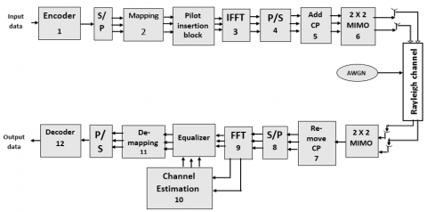
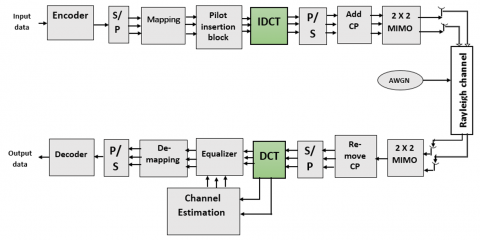
Figure 1 shows the system model of LTE system [8]. It is based on OFDM and FFT technology. It is a multi-carrier modulation technique which divides the frequency spectrum into multiple sub-carriers. The FFT or DCT, is computed using an algorithm that can be used to detect and decode transmitted data. OFDM provides robustness against interference and fading, FFT algorithm enable for efficient data transmission over multiple sub-carriers. LTE can accomplish lower latency and high data rates by using the combination of OFDM and FFT. This combination allowing LTE networks to support more users with less spectrum also allows for efficient resource allocation. LTE also uses advanced coding techniques such as Turbo codes, convolutional codes, and LDPC codes to improve the performance. These enable LTE to give higher data rates with lower error rates [11].
The basic building blocks of an LTE system are in references [12, 13]:
$x(n)=\frac{1}{N} \sum_{n=0}^{N-1} X(k) e^{j\left(\frac{2 \pi}{N}\right) n k}$ (1)
where, $(n=0,1, \ldots, N-1)$, x(n) denotes the input of the FFT, X(k) denote the output of the DFT.
$T_{\text {new }=} T_{\text {orginal }}+T_{c p}$ (2)
Figure 1. Traditional LTE system
Figure 2. Cyclic prefix [12]
$\left[\begin{array}{c}y_1 \\ \vdots \\ y_{M r}\end{array}\right]=\left[\begin{array}{ccc}h_{11} & \cdots & h_{1 M t} \\ \vdots & \ddots & \vdots \\ h_{M r 1} & \cdots & h_{M r M t}\end{array}\right]\left[\begin{array}{c}X_1 \\ \vdots \\ X_{M_t}\end{array}\right]+\left[\begin{array}{c}n_1 \\ \vdots \\ n_{M_r}\end{array}\right]$ (3)
$y=H_x+n$ (4)
where, ($M_t, M_r$) are transmit and receive antennas respectively. x represents $M_t$ dimensional transmitted symbol. n represents $M_r$ dimensional noise vector
$X(k)=\sum_{n=0}^{N-1} X[n] e^{-j\left(\frac{2 \pi}{N}\right) n k}$ (5)
where, $(k=0,1, \ldots, N-1)$.
In DCT-OFDM, the data is first divided into multiple subcarriers, each with its own frequency. The data is then modulated onto each subcarrier using DCT technique. The DCT is an efficient way to encode the data onto the subcarriers because it reduces the time required for data transmission. Additionally, it is also reducing the amount of interference between adjacent subcarriers [15].
The advantage of using DCT-OFDM over traditional OFDM is that it provides better spectral efficiency and higher data rates, its design aligns with the need to efficiently transmit data with minimal errors and signal degradation, ensuring a seamless and reliable user experience for data-intensive tasks. This makes it ideal for applications that require high throughput such as video streaming or file transfers. Additionally, since the DCT reduces the interference between adjacent subcarriers, it also improves signal quality and reliability [16] and it has lower PAPR makes it suitable for battery-powered devices, as it reduces the energy consumption of power amplifiers. Eq. (6) shows the common definition of DCT which is a 1D- sequence of length (N) [17], where u=0,1,2, …, N-1.
$C(u)=\alpha(u) \sum_{x=0}^{N-1} f(x) \cos \left[\frac{\pi(2 x+1) u}{2 N}\right]$ (6)
where, x=0, 1, 2, …, N-1. While $\alpha$(u) is defined as shown in Eq. (7):
$\alpha(u)= \begin{cases}\sqrt{\frac{1}{N}} & \text { for } u=0 \\ \sqrt{\frac{2}{N}} & \text { for } u \neq 0\end{cases}$ (7)
The 2D of DCT is shown in Eq. (8):
$C(u, v)=\alpha(u) \alpha(v) \sum_{x=0}^{N-1} \sum_{y=0}^{N-1} f(x, y) \cos \left[\frac{\pi(2 x+1) u}{2 N}\right] \cos \left[\frac{\pi(2 y+1) v}{2 N}\right]$ (8)
where, $u, v=0,1,2, \ldots, \mathrm{N}-1$, and $x, y=0,1,2, \ldots, \mathrm{N}-1, \alpha(u)$ and $\alpha(v)$ are shown in Eq. (7).
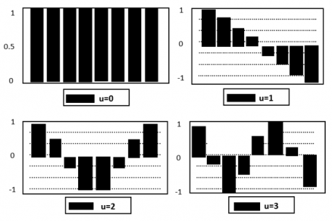
The 1D basis functions (horizontally oriented) and a collection of the same functions (vertically oriented) can be multiplied to produce the basis function of the 2-D DCT. The cosine basis function waves for N=8 are shown in Figure 3. These basis functions are orthogonal [17]. In a DCT-OFDM in LTE system, during transmission, information bits are modulated using real values rather than complex values. These real-valued modulated symbols undergo an (IDCT) operation. On the receiver side, the signal received has traversed a mobile fading channel and been subject to additive noise. Following the removal of symmetric prefix and suffix components, the signal undergoes a DCT transformation. The resulting transformed signals are then input into an Artificial Neural Network (ANN)-based channel estimator and equalizer, which subsequently feeds into a detector. The detector ultimately produces the final set of detected information bits.
DCT is performed using real arithmetic operations rather than complex operations, so offers several advantages over conventional FFT-OFDM in LTE systems, particularly in terms of reducing interference, managing power efficiently, and improving signal integrity. These attributes make it a valuable tool for addressing BER issues and enhancing the performance of LTE networks, especially in challenging wireless environments. Also, it has some potential drawbacks and limitations that warrant consideration like, the use of DCT in LTE systems may require standardized compression and decompression algorithms, which can be computationally intensive, this complexity can increase the processing requirements for both network infrastructure and user devices, potentially leading to higher power consumption and reduced battery life in mobile devices.
Figure 3. The bases of cosine function [18]
Channel- estimation is the process of estimating the characteristics of a communication channel in order to improve the communication system performance, as it allows the receiver to accurately decode the transmitted signal. Channel estimation helps in mitigating the effects of channel impairments, such as multipath fading and interference, by providing the receiver with information about the channel conditions. Also, it is used to design and adapt equalization techniques. Equalization helps to reverse the distortion introduced by the channel, thus enhancing the quality of the received signal. With accurate channel estimates, receivers can employ linear or nonlinear equalizers to compensate for the channel's effects, effectively reducing inter-symbol interference (ISI) and improving BER performance.
Channel estimation can be done in several ways, including using pilot symbols, training sequences, or blind methods. Pilot symbols are known symbols that are sent periodically and used to estimate the channel characteristics, in channels with frequency-selective fading (varying response across subcarriers), pilot symbols are used to estimate the channel response at different subcarriers. This allows for precise equalization and adaptive modulation and coding. Training sequences are known sequences that are sent over the channel and used to estimate the channel characteristics, its suitable for estimating both the frequency-selective and time-varying characteristics of the channel, such as Wi-Fi. Blind methods use algorithms to estimate the channel characteristics without any prior knowledge of the transmitted signal, it may be explored, especially when channel conditions are expected to change rapidly or when the channel is not well-characterized in advance [19]. LTE typically use a combination of pilot symbols and training sequences to strike a balance between accurate channel estimation and efficient use of resources.
According to this estimation approach, the channel is assessed using the weight and bias values of an Artificial Neural Network (ANN). Consequently, the process of channel estimation is substituted with FFNNs. The simulated outcomes, specifically the Bit Error Rates versus the Signal to Noise Ratio, illustrate the ANNs' efficacy in learning and performing channel estimation within a wireless fading channel context. The ANN's inherent learning capabilities are fully harnessed to decode symbols that have suffered degradation due to severe fading in the channel.
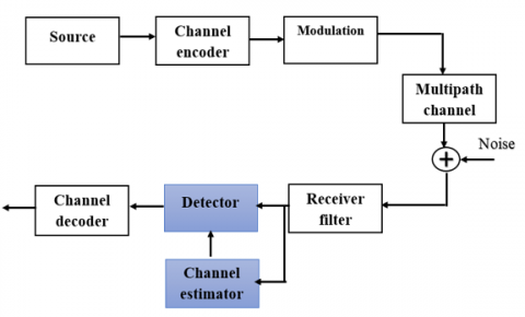
Figure 4 shows the channel estimation and signal detection operations in equalization. The binary signal is modulated and sent over the multipath fading channel after the digital source is typically protected by channel coding. The total signal is received after additive noise has been introduced. The received signal contains some inter-symbol interference (ISI) as a result of the multipath channel. To accomplish proper balancing (ISI elimination). The training sequence of bits, which is exclusive to a given transmitter and is repeated in every transmitted burst, serves as the foundation for channel estimate. The detector receives information from the channel estimator about the channel impulse response (CIR), and the detector uses the sent bits and corresponding received bits to estimate the CIR for each burst independently. A separate channel estimator can perform this task. It should note that ANNs can take a long time as compared to traditional methods.
Figure 4. The block diagram of channel estimator and signal detection in equalization [8]
Signal detectors need to be aware of the channel impulse response (CIR) of the radio link with known transmission sequences. Before the channel's modulated, corrupted signal is demodulated at the receiver, it must first be estimated using LMS, MLSE, MMSE, and other techniques [20]. Eqs. (9)-(10) state the traditional method of estimation [20].
$d(k)=x(n+k-m)$ (9)
$e(k)=d(k)-y(k)$ (10)
where, the required output of d(k) is expressed by y(k), n is the noise added in the channel, m is the delay given to the input signal, and e(k) stands for the instantaneous error signal, is always positive.
The channel fading effects can be greatly reduced by applying a correct equalizer to the received signals. The goal of the equalizer is to use Np known pilot tones and L unknown channel response tap values to estimate and equalize channel. Note that, when no noise is present, the channel impulse response can be accurately retrieved if Np ≥ L. When noise is present, then the families of maximum mean-squared estimator (MMSE) and maximum likelihood estimator (MLE) can be utilized, which yield asymptotically similar performance [21]. Rather than looking into all these approaches, this paper builds on simple frequency-domain OFDM equalization process. For pilot tones located in $\left\{k_1, k_2, \ldots \ldots \ldots, k_{N p}\right\}$ the least square (LS) estimate of the frequency response of channel at pilot tone location can be expressed as:
$H_{k i}=\frac{Y_{k i}}{p_I}$ (11)
$H_{k i}=\frac{H_{k i} P_i+n_{k i}}{P_i}$ (12)
$$H_{k i}=\frac{n_{k i}}{p_I}$$ Channel Error (13)
where, $Y_{k i}=H_{k i} P_i+n_{k i}$
$H$ is the $L S$ estimator and pilot $P_i$ is unit energy, $n_{k i}$ is the noise.
FFNNs are well-suited for this task because they can quickly and accurately adjust the signal strength of incoming signals based on their input. This is done by using a set of weights, which are adjusted based on the input data. The weights are adjusted to make the FFNN's output as close as possible to the desired output.
In Figure 5 the received signal is transformed to frequency domain by taking Fast Fourier Transform (FFT). The estimation and equalization are performed on this signal before they are finally demodulated.
Figure 5. Equalization method [21]
The system observes a channel Hi, which is assumed to be frequency-flat Rayleigh slow-fading, and the coherence bandwidth of the channel is wider than that of individual subcarriers (SCs). Let us denote Xi as the transmitted signal and Yi as the received signal [21]. Then, in frequency domain, a narrowband system facing flat fading can be modeled as:
$Y_i=H_i X_i+n_i$ (14)
where, $n_i$ is AWGN with distribution $N\left(0, \sigma^2\right), X_i$ is the transmitted signal and $Y_i$ is the received signal.
Neural networks are a type of artificial intelligence that is modeled after the human brain. They are composed of inter-connected nodes, or neurons, which process and transmit information. Traditional algorithms are unable to handle some complex problems, such as recognizing patterns in large datasets or making predictions based on past data. They have been used in many different uses, such as autonomous vehicles, image recognition, and natural language processing. The output equations of neural network are seen in Eqs. (15)-(16) [22].
$N e t=s u m=\sum_{i=0}^{n-1} W_i X_i-\theta$ (15)
Output $=f($ net $)$ (16)
where, W denotes the weight of the inputs (x), is the bias of the neuron, and f(net) denotes the activation function, which can be either hard limiter, linear or sigmoid activation function.
Neural networks can adapt and learn from data, which is crucial in LTE systems where channel conditions can change dynamically. Traditional communication systems often rely on fixed algorithms that may not adapt well to changing conditions. Neural networks can continually adjust their parameters to optimize performance under varying circumstances.
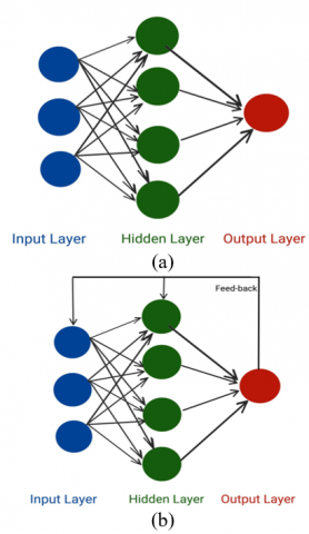
The most common connection ways are feed-forward neural networks and feed-backward neural network [23, 24]. In FFNN information flows only in one direction, from the input to the output layer without any recurrent connection, its typically used for tasks that do not require memory or temporal dependencies, such as image classification, regression, and pattern recognition and its well-suited for tasks with fixed-size input and output data. while FBN permits information to flow both from input to output and back into the network itself. This cyclic structure enables RNNs to have memory or "recurrent" behavior as shown in Figure 6 [23]. This memory is a key feature of RNNs and is what makes them particularly well-suited for tasks involving sequential data or time-dependent patterns. Training RNNs is more complex than FNNs due to the recurrent connections, so FNNs are chosen because they are simpler, more stable, and sufficient for the task.
Figure 6. (a) Feed-forward (FNN); (b) Feed-backward (FNN)
The using of ANNs for channel estimation has main advantage, they are able to capture non-linearity in the channel, which can be difficult to model with traditional methods. It improved the performance in terms of data rate and SNR, because it allows for more accurate estimates of the channel parameters [25, 26]. When it comes to channel estimation, the relationship between the transmitted signal and the received signal is often non-linear due to different factors like interference, multipath propagation, and noise. ANNs can continually adjust their parameters to capture changing non-linear behaviours while traditional linear models may struggle to adapt to dynamic channel environments. By doing so, they can provide more accurate and adaptable channel estimation compared to traditional linear models, it leads to enhance system performance in terms of data throughput, error rates [26]. In the proposed system, FFNN was used by training it to equalize the received data. In order to obtain output data similar to the input data, the neural nodes are provided with the channel estimate value to multiply it adaptively with the received data. This process effectively counteracts the distortions and noise caused by the channel during transmission, so it is considered extremely important. By harnessing the power of FFNNs and channel estimation data, we enhance the robustness and reliability of communication systems, ultimately leading to improved data transmission quality. The limitations or potential challenges of using ANNs for channel estimation is, there is a simple circuit that will be added to the channel estimation, but the results obtained are a value greater than the cost of the circuit. The block diagram of FFNN is shown in Figure 7 below.
The proposed system as compared to reference [9], which studied the variation of different values of the Doppler frequencies (5,50,200) MDS and using the DWT modulation instead of FFT with FFNN-LTE, DWT has good orthogonality because it does not need to CP like DCT this approach minimizes additional power consumption and incurs only a slight reduction in data rate and bandwidth. The result in reference [9] shows that in MDS 5 is better than other MDS but in DWT the system will losses its characteristics when MDS is increased unlike DCT. In the proposed system, utilizing a neural network as an adaptive equalizer will lead to a reduction in BER by enhancing the channel's adaptability, thus improving output reconstruction in relation to the input data. BER of reference [9] is slightly better than the proposed system, but DCT-FFNN-LTE system is faster in implementation and gives results close to reference [9].
Figure 7. Block diagram of FFNN
The proposed system is done by replacing the traditional LTE system with IDCT-OFDM with traditional channel estimation (Pilot aided) as shown in Figure 8, which describes the transceiver of the proposed scheme.
The proposed method DCT is another transform that fulfills the fundamental requirement for FFT function. Here, the complexity of signal processing is reduced and it can be more stable. It can be described as a collection of cos (2π $f_s$ t) wherever so that 0 < t < T, and $f_s$=1/2T which is the minimum subcarriers spacing wanted to fulfill the requirement for orthogonality, and can be given as:
$C=\int_0^T \sqrt{\frac{2}{T}} \cos \left(2 \pi b f_s t\right) \sqrt{\frac{2}{T}} \cos \left(2 \pi m f_s t\right) \mathrm{dt}=\begin{cases}1 & b=m \\ 0 & b \neq m\end{cases}$ (17)
where, C is the complexity.
In our proposed system we transmitted the pilot as a raw of ones (1) through the Rayleigh channel and AWGN effect that make the value of transmitted pilot changed according these effects on path of data, after we find this effect value (will denoted it as X) we can include this effect (X) on received signal to returned it to be similar the transmitted data. This pilot frame will have been used to make channel estimation that's used to compensate the channel effects on the signal. We can find the value of X by Eq. (18) as shown below:
$X=\frac{\text { transmitted pilot value }}{\text { recieved pilot value }}$ (18)
Then we can multiply the received data by X value to obtain the correct data on receiver side.
The second approach is by using IDCT with FFNN as channel estimator to estimating the channel between the sender and the receiver, this is done by training to learn the mapping between the characteristics of the channel and the received signal as shown in Figure 9.
In proposed system FFNN is used in LTE systems, by training it to make equalization for received data through supplying the neural nodes with value of channel estimation to multiply them adaptively with received data to obtain output data similar to input data.
The using of DCT and FFNN will improve the performance of the overall system because, DCT is implemented using real arithmetic operations rather than complex operations, and also FFNNs will used to improve the performance of the system by providing better signal detection and interference cancellation. It can be used to detect and classify signals, reduce interference, and improve the accuracy of channel estimation. FFNN is designed to be fast and reduced the complexity of the system by reducing the number of parameters that need to be estimated. The FFNN that used is not a design Neural but rather its approximate neural so as to reflect the influence of the channel. The cost function of FFNN will be hard limiting activation function.
DCT-FFNN-LTE system as compared to the traditional LTE system would be useful. DCT is not inherently orthogonal like FFT, meaning that there can be some overlap in the frequency domain, potentially leading to interference between subcarriers.so it may have slightly lower spectral efficiency compared to FFT, but when using FFNNs with DCT will reduce interference, or adapt to changing channel conditions intelligently. DCT may exhibit better resistance to certain types of noise and interference due to its energy compaction properties as compared to FFT.
Figure 8. System blocks with DCT-OFDM [9]
Figure 9. System blocks with IDCT-FFNN
In this section the proposed DCT-FFNN-LTE and FFT- systems had been simulated using MATLAB 2016a. The AWGN channel, the flat fading channel, and the selective multipath fading channel were taken into consideration when calculating the BER performance of the suggested LTE system with different MDS value (50, 100, and 200 Hz). All of these scenarios used 5GHz as the carrier frequency with 2×2 antenna and 1024 Multicarrier size, utilizing a greater number of subcarriers enables the simultaneous transmission of more data, thereby enhancing the LTE system's total data capacity. This enhancement results in higher data rates and improved network performance. The type of modulation that used in the proposed system is QPSK, the using of QPSK typically can exhibits better error performance and lower BER than higher-order modulation schemes under challenging channel conditions. It can reliably convey data even in scenarios with moderate. The parameters that used in the proposed LTE system are shown in Table 1.
Table 1. The simulation parameter
|
Parameter |
Value |
|
Multicarrier size FFT or DCT |
1024 |
|
Types of Modulation |
QPSK |
|
Bandwidth of Channel (MHz) |
20 |
|
Channel |
AWGN, flat fading, selective fading channel |
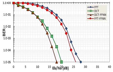
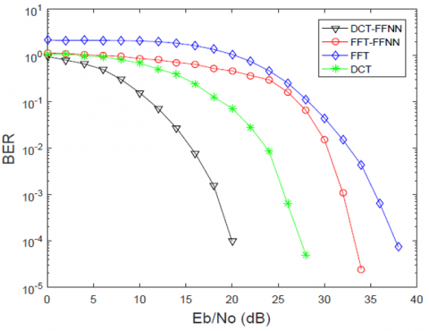
Figure 10 shows the simulation result of LTE system in AWGN channel. The level of comparison that will be taken is BER $=10^{-4}$. and it is shown that in FFT system, the SNR is 27db and it will decrease to 25db when using feed-forward neural network, while when using DCT the SNR will be 19db and decreased to 17db when using DCT-FFNN. From the same figure, it is clearly shown that the proposed LTE-DCT using FFNN is much better than LTE system that based on FFT and FFT-FFNN. To improve system spectral efficiency and performance, the system uses multiple antennas in transmitters.
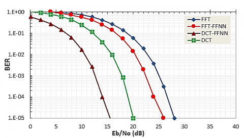
Figure 11 shows the simulation result at flat channel model addition to AWGN in different MDS value, that (DCT-LTE-FFNN) is superior to traditional systems based on FFT transform, FFT transform with feed forward neural network (FFNN), and discrete cosine transform because DCT has better orthogonality and is simpler to implement. Whereas unlike the FFT, which uses orthogonal basis functions (complex exponentials), the DCT uses non-orthogonal basis functions (cosines). This non-orthogonality can be advantageous for capturing non-linear channel effects and handling non-Gaussian noise sources that may be present in wireless channels. When integrated with neural networks DCT can be part of an adaptive system. Neural networks can adaptively learn and optimize the DCT-based processing based on real-time channel conditions, enhancing their ability to equalize and detect signals effectively.
(a)
(b)
Figure 10. LTE performance in: (a) AWGN channel; (b) Flat fading channel in 50 MDS
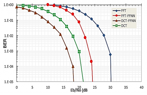
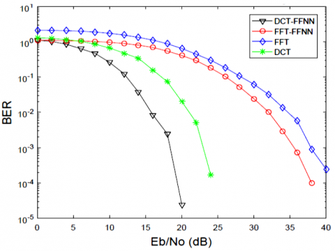
Figure 12 and Figure 13 respectively show the result at selective channel model addition to AWGN in different MDS value 50, 100, 200 Hz, hence transmitted signals will be suffering from a linear phase distortion and constant attenuation through LTE channel model. It can be seen that the LTE system when using feed forward neural network LTE-DCT-FFNN outforms the traditional way that based on FFT and FFT-FFNN and give better BER performance especially at MDS=50 which is much better than LTE based MDS=100 and MDS=200, because when the Doppler frequency increases, it means that the relative velocity between the transmitter and receiver is increasing. This can cause a shift in the carrier frequency of the transmitted signal at the receiver end. If this shift is not compensated for properly, it can lead to errors in demodulating the signal and increase in ICI and thus an increase the bit error rate (BER).
(a)
(b)
Figure 11. LTE performance in flat fading channel in: (a) 100 MDS; (b) 200 MDS
As compared to proposed system, the previous studies [5, 6] which shown in Table 2, used 512 subcarrier size and used only OFDMA or SCFDMA. These studies give better BER performance, but the proposed system which used 1024 subcarriers and involves complex signal processing than other studies give good BER performance as compared to them. The other study [9] used DWT and gives slightly better results than the proposed system, but the difference is that the proposed system faster in implementation and these leads to reduce the hardware complexity of the system.
Table 2. Comparison proposed system with the previous methods
|
References |
Year |
Method |
Channel |
Modulation |
Multicarrier Size |
SNR |
BER |
|
Zhou et al. [5] |
2010 |
DCT-OFDMA |
AWGN |
QPSK |
512 |
16 dB |
10-6 |
|
Pervej et al. [6] |
2014 |
DCT- SCFDMA |
Vehicular an outdoor channel |
QPSK |
512 |
16dB |
10-4 |
|
Shakir et al. [9] |
2019 |
DWT-FFNN-LTE |
AWGN |
QPSK |
1024 |
14dB |
10-4 |
|
The proposed system |
2023 |
DCT-FFNN-LTE |
AWGN |
QPSK |
1024 |
16db |
10-4 |
(a)
(b)
Figure 12. LTE performance in selective fading channel in: (a) 50 MDS; (b) 100 MDS
Figure 13. LTE performance in selective fading channel in 200 MDS
LTE system, proving highly effective in various real-time applications that demand rapid data transmission. These technologies rely on key parameters, namely Signal-to-Noise Ratio (SNR) and Bit Error Rate (BER), which are showcased as robust measurement metrics within the proposed system. This innovative approach not only diminishes Inter-Carrier Interference (ICI) and Inter-Symbol Interference (ISI) but also achieves a desirable BER output, all while preserving the integrity of the input data transmission. In this context, artificial intelligence assumes a pivotal role in enhancing the performance of 4G technologies within the LTE system.
The proposed solution employs a FFNN algorithm combined with Discrete Cosine Transform (DCT) to mitigate ICI and ISI during data transmission. DCT can be used for efficient compression of data in LTE systems, reducing the bandwidth required for data transmission. The DCT process itself, along with additional compression and decompression steps, can introduce latency into data transmission.
The central challenge addressed by this approach is the reduction of BER, yielding remarkable results such as a BER reduction of 20 for MDS=50, 22 for MDS=100, and 26 for MDS=200 in selective fading conditions. These enhancements significantly elevate the system's overall efficiency, ultimately achieving a BER of $10^{-4}$ dB for 1024 subcarriers within the DCT-FFNN-based system.
The results show that Doppler frequency has a significant effect on the BER performance in LTE systems, as the Doppler frequency increases, the BER performance decreases. The performance will be better at MDS 50 and beyond this value, signal degradation occurs, the antennas begin to interfere with one another, leading to signal loss or attenuation.
It also clear that the proposed system in AWGN gives much lower BER and power losses than other channels are used in the paper. In the case of selective fading and flat fading, the DCT-FFNN give lowest BER than FFT in all values of Doppler frequency.
Here are suggestions for works for the future:
I would like to thank Prof. Dr. Osama Qasim supporting my work.
|
$n_i$ |
AWGN with distribution N (0, $\sigma_n^2$) |
|
m |
the delay given to the I/P signal |
|
e(k) |
instantaneous error signal |
|
W |
the weight |
|
Net |
the activation function |
|
C |
complexity |
|
x(k) |
DFT of length N |
|
X(n) |
IDFT an N-point |
[1] Ali, M.A., Barakabitze, A.A. (2015). Evolution of LTE and related technologies towards IMT-Advanced. International Journal of Advanced Research in Computer Science and Software Engineering, 5(1): 16-22.
[2] Ahmadi, S. (2009). An overview of 3GPP Long-Term Evolution radio access network. In: Tarokh, V. (eds) New Directions in Wireless Communications Research. Springer, Boston, MA. https://doi.org/10.1007/978-1-4419-0673-1_15
[3] Ghosh, A., Ratasuk, R., Mondal, B., Mangalvedhe, N., Thomas, T. (2010). LTE-advanced: Next-generation wireless broadband technology. IEEE Wireless Communications, 17(3): 10-22. https://doi.org/10.1109/MWC.2010.5490974
[4] Patidar, L., Parikh, A. (2011). BER Comparison of DCT-based OFDM and FFT-based OFDM using BPSK modulation over AWGN and multipath Rayleigh fading channel. International Journal of Computer Applications, 31(10): 38-42.
[5] Zhou, K., Zhang, J., Xiao, L. (2010). A research on improving the performance of OFDMA system by using DCT/IFFT structure. In the 2nd International Conference on Information Science and Engineering, Hangzhou, China, pp. 1766-1769. https://doi.org/10.1109/ICISE.2010.5689206
[6] Pervej, M.F., Roy, T.K., Sarkar, M.Z.I., Hossen, M.A. (2014). PAPR reduction and BER performance analysis of SC-FDMA system using DFT and DCT methods.
[7] Kondamuri, S.R., Sundru, A. (2020). Non linear companding transform to mitigate PAPR in DCT based SC-FDMA system. Wireless Personal Communications, 112: 503-522. https://doi.org/10.1007/s11277-020-07057-z
[8] Padaganur, S.K., Mallapur, J.D. (2017). A neural network based resource allocation scheme for 4G LTE heterogeneous network. In 2017 2nd International Conference for Convergence in Technology (I2CT), Mumbai, India, pp. 250-254. https://doi.org/10.1109/I2CT.2017.8226130
[9] Shakir, A., Al-Thahab, O.Q.J., Abdul-Rahaim, L.A. (2019). Design of LTE system by using neural network adaptive equalizer based on discrete fourier and wavelet transforms. Journal of Engineering and Applied Sciences, 14(6): 9358-9370.
[10] Burse, K., Yadav, R.N., Shrivastava, S.C. (2010). Channel equalization using neural networks: A review. IEEE Transactions on Systems, Man, and Cybernetics, Part C (Applications and Reviews), 40(3): 352-357. https://doi.org/10.1109/TSMCC.2009.2038279
[11] Jang, J.K., Kim, H.K., Sunwoo, M.H., Gustafsson, O. (2018). Area-efficient scheduling scheme based FFT processor for various OFDM systems. In 2018 IEEE Asia Pacific Conference on Circuits and Systems (APCCAS), Chengdu, China, pp. 338-341. https://doi.org/10.1109/APCCAS.2018.8605617
[12] Andrea, G.S. (2005). Wireless Communications. Cambridge University Press.
[13] Zyren, J., McCoy, W. (2007). Overview of the 3GPP Long Term Evolution Physical Layer. Freescale Semiconductor, Inc., White Paper, 7: 2-22.
[14] Kosanyakun, C., Kotchasarn, C. (2015). A study of insufficient cyclic prefix by using precoding for MIMO-OFDM systems. In 2015 17th International Conference on Advanced Communication Technology (ICACT), PyeongChang, Korea (South), pp. 727-732. https://doi.org/10.1109/ICACT.2015.7224891
[15] Zhou, M., Jiang, B., Li, T., Zhong, W., Gao, X. (2009). DCT-based channel estimation techniques for LTE uplink. In 2009 IEEE 20th International Symposium on Personal, Indoor and Mobile Radio Communications, Tokyo, Japan, pp. 1034-1038. https://doi.org/10.1109/PIMRC.2009.5450015
[16] Myung, H.G., Lim, J., Goodman, D.J. (2006). Single carrier FDMA for uplink wireless transmission. IEEE Vehicular Technology Magazine, 1(3): 30-38. https://doi.org/10.1109/mvt.2006.307304
[17] Al-Thahab, O.Q.J. (2016). Speech recognition based radon-discrete cosine transforms by Delta Neural Network learning rule. In 2016 International Symposium on Fundamentals of Electrical Engineering (ISFEE), Bucharest, Romania, pp. 1-6. https://doi.org/10.1109/ISFEE.2016.7803208
[18] Khayam, S.A. (2003). The discrete cosine transform (DCT): Theory and application. Michigan State University, 114(1): 1-31.
[19] Dubey, N., Pandit, A. (2019). A comprehensive review on channel estimation in OFDM system. International Journal Online of Science, 5(3): 1-4. https://doi.org/10.24113/ijoscience.v5i7.201
[20] Sanjana, T., Suma, M.N. (2014). Comparison of channel estimation and equalization techniques for OFDM systems. Circuits and Systems: An International Journal, 1(1): 1-10.
[21] Shahriar, C., Clancy, T.C., McGwier, R.W. (2016). Equalization attacks against OFDM: Analysis and countermeasures. Wireless Communications and Mobile Computing, 16(13): 1809-1825. https://doi.org/10.1002/wcm.2648
[22] Haddadi, F., Khanchi, S., Shetabi, M., Derhami, V. (2010). Intrusion detection and attack classification using feed-forward neural network. In 2010 Second International Conference on Computer and Network Technology, Bangkok, Thailand, pp. 262-266. https://doi.org/10.1109/ICCNT.2010.28
[23] Krenker, A., Bešter, J., Kos, A. (2011). Introduction to the artificial neural networks. Artificial Neural Networks: Methodological Advances and Biomedical Applications. InTech, 1-18.
[24] Zupan, J. (1994). Introduction to artificial neural network (ANN) methods: What they are and how to use them. Acta Chimica Slovenica, 41: 327-327.
[25] Abiodun, O.I., Jantan, A., Omolara, A.E., Dada, K.V., Umar, A.M., Linus, O.U., Arshad, H., Kazaure, A.A., Gana, U., Kiru, M.U. (2019). Comprehensive review of artificial neural network applications to pattern recognition. IEEE Access, 7: 158820-158846. https://doi.org/10.1109/ACCESS.2019.2945545
[26] Ye, X., Yin, X., Cai, X., Yuste, A.P., Xu, H. (2017). Neural-network-assisted UE localization using radio-channel fingerprints in LTE networks. IEEE Access, 5: 12071-12087. https://doi.org/10.1109/ACCESS.2017.2712131