Singgih Dwi Prasetyo![]() | Zainal Arifin*
| Zainal Arifin*![]() | Aditya Rio Prabowo
| Aditya Rio Prabowo![]() | Eko Prasetya Budiana
| Eko Prasetya Budiana![]() | Mohd Afzanizam Mohd Rosli
| Mohd Afzanizam Mohd Rosli![]() | Noval Fattah Alfaiz | Watuhumalang Bhre Bangun
| Noval Fattah Alfaiz | Watuhumalang Bhre Bangun
© 2023 IIETA. This article is published by IIETA and is licensed under the CC BY 4.0 license (http://creativecommons.org/licenses/by/4.0/).
OPEN ACCESS
Solar energy, harnessed from sunlight, can be efficiently converted and transmitted for various applications when coupled with photovoltaic cells and solar heat collectors. A photovoltaic thermal (PVT) collector not only aids in sustaining the power output of the photovoltaic module but also leverages a solar collector to generate heat, thereby facilitating cooling. The performance of PVT systems has been scrutinized by researchers through the implementation of diverse collector designs and fluids. Round and rectangular collector designs prevail as the most extensively utilized models. The materials adopted for collectors in the majority of PVT system evaluations are predominantly copper, with aluminum as an alternative. Several researchers have enhanced the performance of solar systems by integrating collectors with the addition of fins. This review examines numerous studies on PVT systems featuring optimal fins, aiming to concurrently augment both electrical and thermal efficiencies. Furthermore, this research intends to assess a variety of collector designs that have been employed in anticipation of performance improvements.
photovoltaic, solar energy, thermal collectors, designed fins
Research in the field of photovoltaic technology has consistently demonstrated that a rise in temperature of the photovoltaic cells precipitates a decrease in voltage across the photovoltaic module. This, in turn, culminates in a reduction in the overall electrical efficiency of the system, and extreme temperature increments can potentially inflict damage upon the PV panels [1-3]. This challenge can be mitigated by the implementation of a cooling system, either passively or actively, thereby maintaining the solar panel’s performance at an optimum level [4].
A widely adopted cooling methodology is the utilization of a photovoltaic thermal collector (PVT), a system that not only sustains the power output of the PV module but also generates heat. The simultaneous heating of electricity and fluids presents considerable economic advantages [5, 6].
The PVT is a hybrid collector that amalgamates a solar heat dissipation mechanism with a photovoltaic module. Thermal collectors are designed to cool photovoltaic modules through heat dissipation, and concurrently harness the heat to generate thermal energy [7, 8]. Incoming solar energy is converted into electrical energy by the photovoltaic module through the photovoltaic process. The energy conversion process results in a consistent temperature increase in the cell due to the heat absorbed by the semiconductor materials. When the photon energy of light impinges on the N-type semiconductor, electrons within the N-type semiconductor can be liberated, thereby converting radiant energy into electricity. However, not all solar energy can be transmuted into electrical energy. In a PVT system, excess heat is partly transferred back to the environment via convection, while conduction facilitates the transfer of the remaining heat to the heat sink [9]. The base fluid is guided into the PVT collector from the fluid source via the absorber tube or flow channel. This fluid subsequently absorbs heat from the pipe walls to transport the heat to the outlet joint. A conventional PVT collector employs multiple components [10].
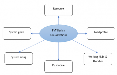
Since heat transmission is the core function of a solar thermal collector, enhancing the quantity of heat transfer through design and optimization is pivotal [11]. As illustrated in Figure 1, numerous factors must be considered in the design of a PVT. Deciding whether the PV system is to generate hot water from solar heat sinks while concurrently cooling PV modules plays a significant role in determining the configuration of the PV system [12]. If the system is intended to operate in a grid-connected configuration, the requisite hardware, such as inverters, power meters, AC circuit breakers, must be included [13]. An understanding of the electric-thermal requirements necessitates the consideration of the load profile. Following an accurate evaluation of the load profile, the PVT system can easily be scaled. Adequate resources are required to examine the resources in the PVT installation area [14]. Factors such as sunlight, ambient temperature, wind speed, and the average number of wet days per month must be taken into account to properly size a PVT system to meet both thermal and electrical requirements. Another resource is the area allotted to the PVT system. The nature of the installation area is another crucial consideration [15].
The working fluid, insulation, and the shape and arrangement of the absorber significantly influence heat transmission. Heat transmission between the PV and absorber is integral to the cooling process [15]. The heat transfer process can be optimized by using a heat transfer fluid with superior thermophysical properties than water or by increasing the surface contact between the absorber and the PV module [16, 17]. Additionally, the modeling of the PVT system can be customized based on the desired thermal or electrical energy needs. Regardless of the load and PV module used in the PVT, the large cross-sectional area of the thermal collector becomes more dominant [18].
Figure 1. PVT design considerations
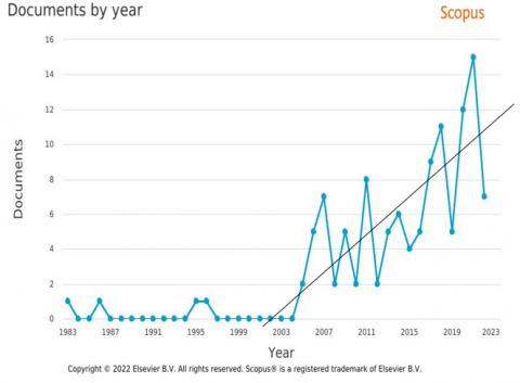
Optimizing the parameters of the photovoltaic thermal collector system is done by combining active cooling systems and also passive cooling. One of the combination system developments and there is still a great possibility for further growth is the combination of finned photovoltaic thermal collector systems [19]. Combining collectors with the addition of fins has been used by several researchers to improve system performance in solar systems. Research has been successfully published in journals with a Scopus index over the previous four to five years. According to Figure 2, 117 papers have been gathered using the keywords Photovoltaic Thermal Collector Fins, and there is a yearly increase in this number. The study conducted by numerous researchers over the past 4-5 years based on these keywords is the major subject of this review paper.
As shown in Figure 2(a), several finned PVT systems are reviewed, so that the reader can assess the best application of fins in optimizing PVT performance. A finned PVT technique summary regarding the characteristics is presented to obtain important information regarding the development of finned PVT technology.
(a)
(b)
Figure 2. (a) Scopus publication with keywords photovoltaic thermal collector fins; (b) Most prolific authors in the field of fins design on PVT
(a)
(b)
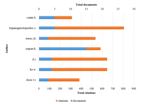
Figure 3. (a) Time overlay visualization of the countries of residence of the associated authors of the relevant publications; (b) Topic-related overlay map with PVT keywords
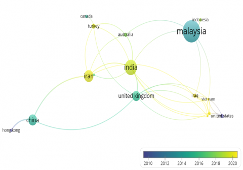
Figure 2(b) illustrates several previous studies discussing fins in PVT systems. There are a total of 30 reference sources that have been published with several documents cited more than 100, in addition to the number of citations that have been reported as many as 3,440 from the keyword fins PVT. Research conducted by sopian k. has the most published results of scientific papers, while Tripanagnostopoulos can produce scientific work with the greatest number of citations compared to other researchers with a total of more than 800 citations.
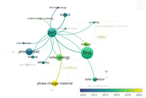
A time overlay visualization of countries that published design-related scientific articles on PVT between 2010 and 2020 is shown in Figure 3(a). Malaysia appears to be the country with the most publications, followed by India, Iran, United Kingdom, China, Australia, Canada, United States, Turkey, and Hong Kong. With an average publication date of 2018-2020, Malaysia, India, and Iran are countries that are intensively pursuing methods of increasing efficiency in solar panels using PVT methods integrated with fins.
Related reference publications from the previous decade are contained in Figure 3(b). Some general issues are still often discussed such as the utilization of thermal energy and efficiency, but several issues have recently begun to be highlighted such as modeling, development of PVT systems, fins, nanofluids, phase material change (PCM), and energy and exergy analysis highlighted in yellow and green.
In the last few decades, the PVT system has shown significant potential for development. There have been many studies from various countries discussing the development of PVT systems. In the early stages of development, the PVT system was only modeled by adding fins, and then innovations were made to the thermal collector geometry used. Additionally, the performance of this system has been improved by using other heat-conducting materials, such as nanofluids and PCMs. In recent years, this issue has become the most frequently discussed, especially in terms of the energy and exergy produced. Optimizing this system is interesting to discuss because it can produce both electrical and thermal energy simultaneously.
Thermal Collector is a set of tools or devices attached to the bottom of a photovoltaic panel that can generate electricity and heat energy with higher efficiency than photovoltaic modules in general [16]. This configuration allows for heat reduction through conduction between the thermal collector and the bottom of the solar panel, while heat from the collector is removed by the working fluid. Recent studies have discussed improving PVT system efficiency through modifications to the thermal collector design, fluid flow direction, use of different working fluids, and other methods [17, 20, 21]. One of the most frequently used methods is changing the geometry of the thermal collector to expand the contact surface between the collector and panel.
(a) Rectangular tube
(b) Round pipes
(c) Rectangular shaped-channel
(d) Rectangular hollow tubes
(e) Harp-channel
(f) Grid-channel
(g) Mini cooler block
(h) Full cooler block
Figure 4. Types of collector designs
The contact surface has a linear relationship with the rate of heat transfer that occurs between the two objects that are in contact with each other. However, in designing a thermal collector, several other parameters must also be considered, such as losses and pressure drops that can occur in the flow because they have a significant influence [22]. In addition, the material used also needs to be considered because it has a substantial impact on the heat transfer characteristics that occur in the thermal collector. The contact surface has a linear relationship with the rate of heat transfer that occurs between the two objects that are in contact with each other. However, in designing a thermal collector, several other parameters must also be considered, such as losses and pressure drops that can occur in the flow because they have a significant influence. In addition, the material used also needs to be considered because it has a substantial impact on the heat transfer characteristics that occur in the thermal collector [23, 24]. The contact surface has a linear relationship with the rate of heat transfer that occurs between the two objects that are in contact with each other. However, in designing a thermal collector, several other parameters must also be considered, such as losses and pressure drops that can occur in the flow because they have a significant influence. In addition, the material used also needs to be considered because it has a substantial impact on the heat transfer characteristics that occur in the thermal collector [25].
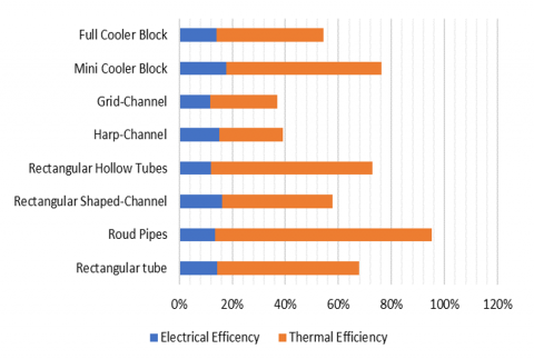
Research on optimizing the efficiency of PVT devices through modifying the geometry of the thermal collector has often been carried out using comparative parameters in the form of electrical efficiency and thermal efficiency as a performance evaluation of several configurations that have been implemented. Figure 4 shows several different thermal collector geometry arrangements using similar materials and working fluids. This study aims to see the effect of the contact surface area between the photovoltaic panel and the thermal collector accompanied by the influence of the flow rate that occurs inside the collector. If, observing Figures 4(a) and 4(b) have almost similar geometries with the same flow direction. The difference between these two images is the shape of the connection between one pipe and the other in the form of rectangular tubes and round tubes. The rectangular tube thermal collector configuration can produce an electrical efficiency of 14.30% and thermal efficiency of 53.40%, meanwhile, the thermal collector round pipes can produce higher thermal efficiency at 81.73%, but there is a decrease in electrical efficiency to 13.52% [26, 27].
This event can occur because the electrical efficiency is greatly affected by the decrease in the temperature of the photovoltaic panels which has a linear relationship with the increase in the contact surface area. Meanwhile, thermal efficiency is affected by the flow rate of the working fluid in the collector in delivering heat, so the shape of the round pipe thermal collector will have smaller flow losses in the pipe. Almost the same results are also shown in Figure 4(c) which shows that the Rectangular Shaped-Channel configuration can produce greater electrical efficiency due to the larger contact surface area. Figure 4(c) uses several pipes arranged in series with different sizes through separate inlet and outlet channels so that it has a lower thermal efficiency because the flow pattern has not yet entered the turbulent phase. Electrical efficiency is 16.27% and thermal efficiency is 41.50% for the Rectangular Shaped-Channel Thermal Collector design [28]. Figure 4(d), on the other hand, employs a rectangular hollow tube thermal collector design that yields a thermal efficiency of 61.00% and an electrical efficiency of 11.90%. Pay close attention, because the flow pattern has entered the turbulent phase, and the acquired thermal efficiency is rather high [29].
The next thermal collector geometry is modeled in the form of a channel as shown in Figures 4(e) and 4(f) and 4(c). Configuration of the Harp-Channel is shown in Figure 4(e) with a shape resembling Rectangular Hollow Tubes with double inflow from the right and left. The existence of double flow can make the temperature distribution in the collector more even because the temperature of the working fluid can be maintained. From this configuration, an electrical efficiency of 15.00% is obtained, but only a thermal efficiency of 24.10% is obtained [30]. Meanwhile, Figure 4(f) is a Grid-Channel configuration with geometric shapes resembling Figure 4(d) with more and more complex flow junctions. Thermal efficiency is 25.20%, while electrical efficiency is 11.80%when this shape is used [30]. Despite having a greater contact surface area, the PVT system performs worse than rectangular hollow tubes, according to the performance values obtained. As a result of the numerous variations in flow patterns that take place in this design, the results obtained show that the number of complicated connections can lower the working fluid's efficiency.
Figures 4(g) and 4(h) show a geometric cross-section with a cooler block shape designed to maximize the contact surface between the thermal collector and the photovoltaic panel. Figure 4(h) is a full cooler block configuration that has the largest contact surface area when compared to other shapes. This geometry can produce an electrical efficiency value of 14.00% and a thermal efficiency of 40.40% [31]. The shape of the mini cooler block configuration is designed to improve some of the weaknesses that exist in the full cooler block configuration. In the mini cooler block collector design, an electrical efficiency value of 17 is obtained, 69% which is the highest electrical efficiency value when compared to other configurations as shown in Figure 5. The thermal efficiency value was obtained at 58.50% which indicates that this collector design can correct some of the deficiencies of the full cooler block design because the area of the thermal collector can be reached with a more uniform working fluid effectiveness. Parameters in the form of thermal efficiency and electrical efficiency must be considered in designing a thermal collector in a PVT system. 50% which indicates that this collector design can correct some of the deficiencies of the full cooler block design because the area of the thermal collector can be reached with the effectiveness of a more uniform working fluid [32].
Figure 5. PVT efficiency of each collector design
There have been numerous studies on optimizing the efficiency of PVT devices through modifications to the thermal collector geometry, evaluating both electrical and thermal efficiency. Improvements in efficiency can be achieved by maintaining the working panel temperature at an optimal level, even under high solar radiation intensity. Heat transfer within the PVT panel occurs through both convection and conduction, where a larger cross-sectional area can enhance the heat dissipation process. However, some findings have shown conflicting tendencies. While a larger surface area can facilitate heat dissipation, complex connections may lead to reduced working fluid effectiveness due to changes in flow patterns. Excessive fluctuations may cause heat flow to accumulate at a particular point, resulting in suboptimal performance.
4.1 PVT system in the form of fin
A heatsink is a passive heat control system that may absorb heat to help keep the final temperature stable. Due to its capacity to disperse heat in electronic chambers, this device has been utilized extensively by numerous authors to manage the thermal effect in solar panels. Cheong Tan et al. [33] used aluminum foam in concentrated solar cells as a heat sink (CPV). Before inserting aluminum foam into a concentrated solar cell, the effects of porosity and pore density were initially studied to check for thermal performance. The optimum optimization is provided by aluminum foam with a porosity of 0.682 and an average density of 10 pores. At a flow rate of 40 g/s and a temperature of 55.10℃, they may enhance the heat removal process and temperature uniformity. Aluminum heat sinks on PV panels were simulated computationally and experimentally by Arifin et al. [34]. When the simulation was run, the operating temperature of the PV panel dropped by 10%. Additionally, according to the trial findings, the surplus heat in the panel dropped from 85.30℃ to 72.80℃, boosting power generation by 18.67%. Halogen lights and a heat sink cooling system are used by Soliman et al. [35] to replicate artificial solar radiation for PV cells. When the heat sink is utilized with natural and forced air, the cell efficiency rises to approximately 8% and 16%, respectively, and the surface temperature is decreased by 5.4% and 11%, respectively. A revised Nusselt number is suggested to further improve the performance of the PV module. The expanded fin heat sink system is better equipped to disperse huge quantities of heat from the solar module. Additionally, heatsinks may be used in PVT systems with a variety of fin designs and forms that have been designed.
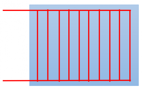
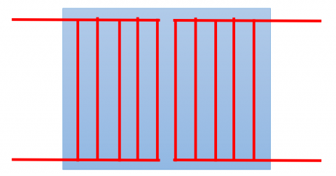
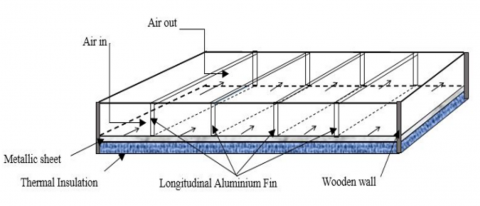
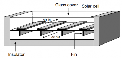
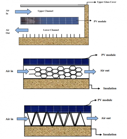
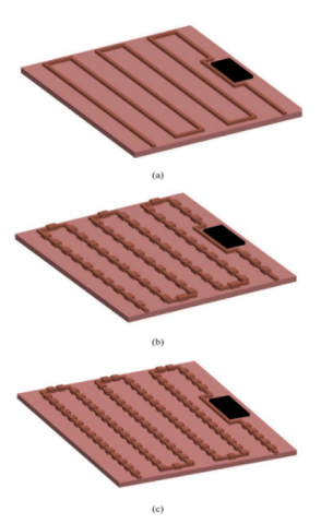
A stationary solar air collector device has been designed by Mojumder et al. [36] to determine the overall performance of the PVT under a specified longitudinal fin geometry for a given range of solar irradiance and mass flow rate. The gadget has a collector top made of polycrystalline silicon photovoltaic (PV) cells, separated from it by a polyvinyl fluoride (PVF) sheet. Figure 6(a), which depicts a cross-section of the fin location in the channel and the direction of airflow, demonstrates this. For forced airflow through the converging portion, four fins of 300 mm each are positioned longitudinally along the duct, separating the panel section into five equal pieces. The two parallel boundary walls, which serve as secondary heat exchangers, arrange the fins parallel and evenly spaced from one another. Othman [37] investigated the performance of an air heater on a double-pass photovoltaic-thermal with fins placed in the channels of both flow channels parallel to the length of the collector as shown in Figure 6(b). The top channel, which is made of a glass cover and solar panels and is directly heated by the sun, circulates incoming air. The airflow then enters the bottom channel created by the solar panel and the rear plate. The solar panels' rear fins can enhance heat transmission to the air and boost the effectiveness of the entire system. Turbulence might happen because the presence of a barrier disturbs the flow of power through the fins. The increase in the heat transfer coefficient is made possible by turbulence. Fins, meanwhile, can offer more space for heat transfer. The pace at which heat is transferred from the plates to the moving air can be accelerated by combining the two occurrences.
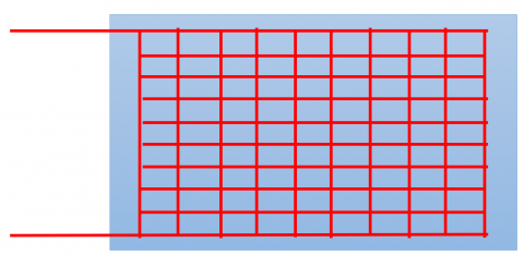
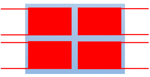
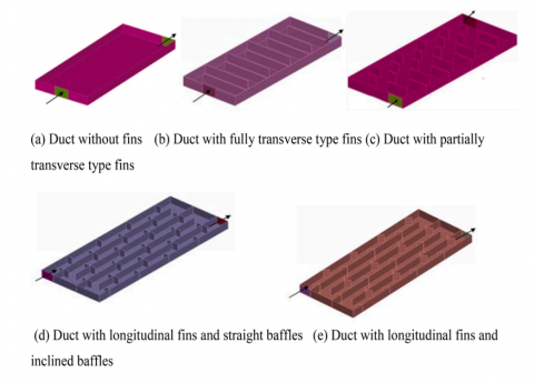
The channel on the thermal collector is modeled using the simulation approach employing five different channel geometry forms, as illustrated in Figure 6(c). The surface temperature of the panel reaches 65℃ in duct configuration without fins. In contrast, in ducts with fully transverse fins, partially transverse fins, longitudinal fins with straight baffles, and longitudinal fins with inclined baffles, the temperature was reduced to 62℃, 61℃, 58℃, and 56℃, respectively. When cooling channels with longitudinal fins and inclined baffles are used, energy performance may be raised from 20% to 28% and thermal performance from 12% to 18% [38, 39]. According to Figure 6(d), Kumar and Rosen [40] compared the performance of a double-pass PVT air collector with a typical PVT air collector. The thermal and electrical values may be raised by 15.5% and 10.5%, respectively, as compared to traditional PVT collectors, by enhancing the fins in the bottom channel. The PVT air collector with a honeycomb heat exchanger is still the subject of experimental research. System-generated thermal efficiency value was significantly increased. Thermal efficiency may reach a value of 87% with an intensity of solar radiation of 828 W/m2 and a mass flow rate of 0.11 kg/s [41]. Othman et al. [42] then continued by putting out the concept of a PVT air collector with a v-grooved absorber plate. According to the trials that were conducted, the electric efficiency value significantly increased by around 17%.
4.2 PVT combination with fin
Using fins that are integrated with other cooling systems installed outside the thermal collector in the form of PCM or other cooling media, PVT and fins together are a technique for improving heat absorption systems in solar panels. When the amount of sunshine is high, phase change materials (PCM) are a common cooling medium used to store extra heat in solar collectors [43]. Several research using PCM attached to solar cells and acting as a cooling system have been conducted to boost the efficiency of solar collector photovoltaic power. PV modules can avoid overheating thanks to PCM's ability to absorb a significant amount of heat during the phase shift process. The five PCMs used in the studies by Hassan et al. [44] had latent heats ranging from 140 to 213 kJ/kg and melting temperatures of 21 to 29℃. It investigated how the PV/PCM system and the weight of the PCM affected those factors. Huang [45] researched how the use of two PCMs affected performance thermal regulation. With the suggested setup, a PV system may operate for a prolonged amount of time at a lower temperature. After studying PCM in various combinations, it was shown that the thermal regulation performance of a PV/PCM system depends on (a) the mass of the PCM, (b) the location of the PCM in the PV/PCM system, (c) the thermal properties of the PCM, and (d) the structure of the PV/PCM. By utilizing PCM, Xu et al. [46] assess several strategies for lowering the operating temperature of PV modules. They created a numerical model that can explain how a PV/PCM system behaves.
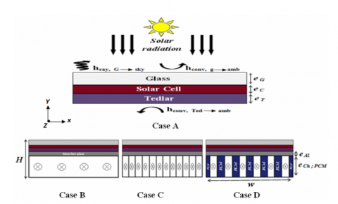
Better temperature distribution in solar cells may come from the integration of PCM and PVT systems since the heat energy stored during PCM melting can be recovered again after sunset [46]. Several tests were carried out by Simón-Allué et al. [47] to study the behavior of PVT panels. They claimed that after subtracting solar irradiation, they were able to reach thermal values of up to 30% utilizing PCM in a PVT system. A three-dimensional analysis of hybrid photovoltaic thermal (PVT) systems with fins was carried out by Ahmed and Nabil [48]. Figure 7(a), which covers four distinct instances, illustrates the cooling impact of air, PCM, and air-PCM combinations. An uncooled system is Case A. In Case B, a cooling duct is installed beneath the absorber. In example C, the air duct beneath the absorber is given fins. The PCM air cooling is inserted between the fins of Case D. Aluminum, glass, silicon, Tedlar, and hybrid photovoltaic thermal (PVT) are employed in its construction. RT31 is the PCM in use. In a PVT hybrid system, PCM use can enhance silicon cooling, and PCM thickness has an impact on the already-existing cooling mechanism. Best cooling is obtained when PCM is combined.
(a) One stream fin
(b) Two stream fins
(c) Variation of fin position
(d) Variation of fin shape
Figure 6. Types of the designed fins [32, 36, 38, 39]
The literature above has covered several significant research that has been conducted on PVT/PCM units. However, past research has seldom ever evaluated the impact of using fins in PCM containers on the performance of PVT/PCM units. To investigate the productivity of PVT/NEPCM units, several NEPCM-integrated photovoltaic/thermal collector designs were created using Space Claim software. Figure 7(b), which displays the actual physical geometry used in the simulations, shows the 3D simulation model. It should be noted that monocrystalline silicon PV units, Tedlar layers, and EVA layers are components of every PVT system (Ethylene-vinyl acetate). Due to the geometry's extremely thin thickness, an anti-reflective coating layer is required; nonetheless, the coating effect has been taken into account for the glass coating that was employed. One of the risers is taken into consideration as a computational domain in this study to decrease computation time and cost [49].
From several combinations of PVT systems that have been conducted, the effect of heat dissipation channels has become a common issue to be modeled. In addition, direct integration of fins can assist in the process of releasing heat to the environment more effectively. In some models, non-uniform flow patterns were shown to be possible, which could lead to a pressure drop in the fin channels within the collector. Creating channels by integrating PCM had a relatively insignificant effect, but it was enough to maintain heat at an appropriate level. Most of the research conducted so far has been in the form of simulation testing, so there is a possibility of manufacturing errors due to the complex modeling.
5.1 PVT integration with fin beyond the collector
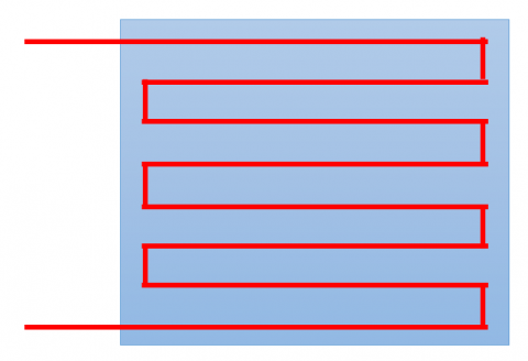
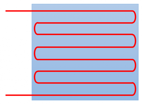
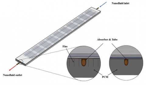
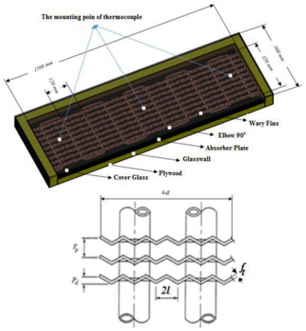
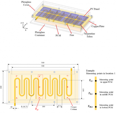
Solar water heater applications can take advantage of PVT with the addition of fins outside the collection. Water heaters that use solar energy as their energy source and water heating medium are known as solar water heaters. The solar panels' heat will be sent to a water storage tank where it will be utilized to heat the water and make it ready for daily usage. A flat plate collector with a modest efficiency is the type that is frequently used in solar water heaters. The heat absorption area can be enlarged to improve this efficiency. When fins are added to solar collectors, their performance outperforms that without them. Figure 8(a), which depicts the geometry of the collector of a solar water heater with the addition of corrugated fins, was used in Maskur and Dwiyantoro's [50] study to examine the effects of adding corrugated fins to the collector. The 1.59 cm in diameter and 0.5 mm in thickness copper pipes are placed in a serpentine pattern. The solar collector's absorber plate is a 1.5 m × 0.5 m zinc plate that has a 5 mm thick cover glass installed. Use glass wool insulation with a 5 cm thickness to anticipate the impact of limiting heat loss to the side and bottom of the collector. Research on solar collectors has also been carried out by Xu et al. [51] using the PVT-PCM system. The Thermal Collector is the main component of the PVT-PCM system whose detailed configuration can be described in Figure 8(b) which displays the arrangement of the solar collector. The PCM also includes information on the thermocouple. To measure the temperature of the top, middle, and bottom PCM layers in the solar collector, nine tiny copper columns with three thermocouples placed on each are installed on the back of the copper plate. During experimental testing, the setting's goal is to pinpoint PCM temperature stratification. As a result, the average temperature over nine segments (Ti-j) may be used to represent the PCM temperature in the solar collector. The notation I represent the horizontal plane from top to bottom in the z direction, while the notation j represents the order from left to right in the direction x. Additionally, heat transfer mechanisms that may occur in solar collector devices that are combined with heat exchangers are identified using mathematical modeling.
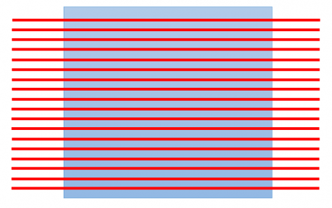
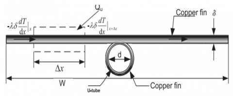
As determined by Paradis et al. [52], Figure 8(c) depicts the heat balance on the serpentine-shaped differential element of the solar absorber plate above the heat exchanger. Modeled as dxdyp for the length of the tube element and dz for the volume of the solar absorber plate element. While the zf axis is the longitudinal axis of the serpentine tube and follows the alignment of the heat exchanger system on the tube, the x and y axes are employed as the bounds of the spatial temperature distribution on the plate. Tong et al. [53] make a few straightforward assumptions to simplify their study because the system they are using is still too complicated. There are two heat absorber tubes and copper fins directly attached to a flat plate collector. Through this combination, heat is expected to be dissipated more efficiently as it has two streams with intersecting directions. These different heat dissipation directions are expected to optimize heat absorption from the plate. The absorber tube is first assumed to be parallel to the copper fins and modeled as a flat plate. The thickness of the absorptive layer is assumed to be very thin, so there is no significant temperature gradient in either the radial or flow direction along the tube. Based on the aforementioned hypotheses, it is possible to examine the heat balance of copper fins, as illustrated in Figure 8(d), which displays the arrangement of copper fins. By multiplying the fin length, (Wd)/m2, by the width x in the flow direction's critical region.
5.2 PVT integration with fins in the collector
Shahsavar et al. [54] conducted experimental research on the utilization of fins in collectors, focusing on three distinct PVT system situations. The PVT system in the first instance is set up as a sheet and simple serpentine tube collector (PVT-0S). The PVT system's collector in the second instance has sheet- and four-finned serpentine tubes (PVT-4S). In the third instance, the PVT system's collector had sheet-and-serpentine tubes with eight fins (PVT-8S). To compare the energy and energetic performance of these three experimental systems, designers and manufacturers created them. The tube has an inner diameter of 8 mm and a thickness of 2 mm. The collector was made of copper, and thermal grease was used to seal the tube to the PV module. The fins taken into account in the research are 1.6 mm in height and 0.8 mm in breadth. The bottom of the collector surface is soldered to the serpentine tube in use. To stop heat from escaping from the tube's vicinity, it is further utilized wrapped in stone wool insulation. Figure 9(i) shows a schematic representation of how the thermal collector was created.
(a) Collector transverse fin
(b) Collector parallel fins
(c) Collector attached fins
(d) Collector's fused fins
Figure 8. Integration of PVT with fins outside the collector [51-53]
(a) Transverse fin
(b) Circular fins
Figure 9. Integration of PVT with fins in the collector [54, 55]
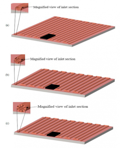
According to an examination of the generated energy and exergy, Shahsavar et al. [55] inquiry also employed a rifled serpentine tube to examine three experimental PVT system scenarios utilizing nanofluids. A basic parameter or standard PVT system, or plain serpentine tube PVT system, is the first example. The other two PVT systems were adaptations of the conventional PVT system, and they included swapping out the plain serpentine tube with threaded serpentine tubes with three ribs (3-start rifled PVT system) and six ribs (six-rib PVT system) (6-start rifled PVT system). The serpentine tube's measurements are 8 mm in diameter and 2 mm in thickness, and it is constructed of copper. By using thermal grease, the collector is placed at the rear of the PV module, and a soldering procedure is used to join the serpentine tube to the collector surface. The rib pitch in the 3-start and 6-start rifled PVT systems is 1 mm, with a height and breadth of 0.4 mm. The schematic configuration of the fins employed in the collector is depicted in Figure 9(b), Based on the three cases observed in the basic PVT system, both a 3-start and a 6-start rifled PVT system are available. It has been discovered that raising the flow rate and nanofluid concentration in the three PVT system scenarios from 20 to 80 kg/h will enhance their thermal performance. Furthermore, it has been shown that 6-start rifled PVT systems may operate at their maximum efficiency of 22.5%, with average values that are 5.9% and 1.9% greater than those of normal rifled PVT, respectively. At a flow velocity of 80 kg/h and a concentration of 2% nanofluid, this efficiency value is feasible. Additionally, as compared to PV modules without cooling at the same intensity, it may generate 31.5% more electric power by using a 6-start rifled PVT system.
5.3 Fronted Financing PVT
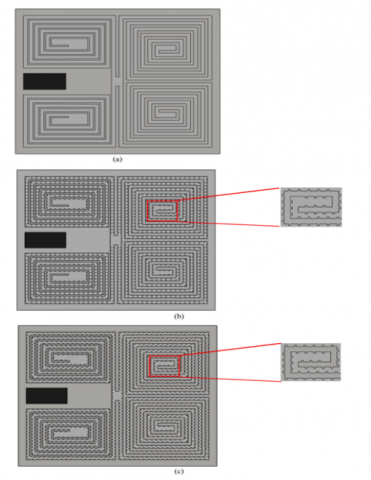
The two most crucial areas examined to improve a PVT device's efficacy are PVT system setup and working fluid parameters [56]. Making grooves in the thermal collector pipe is one method that can be used to increase the heat transfer process that occurs by expanding the contact surface without affecting the flow rate of the working fluid in the thermal collector. This modeling of the thermal collector is being done to maximize the contact surface area with the photovoltaic panel. The sheet and serpentine tube collector from the PVT system used in Shahsavar et al. [57] investigation is depicted in Figure 10(a). In this study, a sheet-type and plain serpentine collector atop a grooved serpentine tube collector was used to increase the energy and exergy performance of the PVT system. Copper serpentine tubes are welded to the bottom of copper plates, which are then positioned beneath the PV panels using thermal grease. The nanofluid will receive the heat that is delivered from the PV panel to the serpentine tube. The tube is insulated with stone wool so that heat cannot escape into the surroundings.
A simple and sheet-type serpentine tube collector, the collector in Figure 10(a) shall be referred to as the "I-case" from here on. With 8 mm in length and 2 mm thick sides, the tube features a rectangular cross-section. Figures 10(b) and (c), which are depicted as cases II and III, respectively, are novel collectors that have grooved serpentine tubes. The number of plots in instance III is more than in case II, which is how the various cases that have been presented differ from one another. Case-groove II's pitch is 8 mm, whereas case-is III's is 5.4 mm. The grooved side length is 12 mm on the notched collector. Grooving in the serpentine tube will result in constant disruption of the thermal boundary layer, accelerating the passage of heat from the tube wall to the nanofluid and accelerating the cooling of the solar panel. Additionally, the design of the grooves in the serpentine tube affects lowering the nanofluid pressure and boosting its pumping ability, both of which reduce the electrical energy produced by the PVT system. The configuration based on case-III yields the best effective value out of the several instances that have been evaluated for the grooved fin cross-sectional shape shown in Figure 10(a). In Case III, it is possible to attain an overall maximum energy efficiency of 83.47% with a ratio of 15%, which is 6% better than what Cases I and II were able to do. With a ratio of 4.6% and 2.3% greater than examples I and II, case III produced an overall maximum exergy efficiency of 14.43%. Case III, with a value of 12.38%, attained the highest electrical energy efficiency among the three examples. This value was 3.3% and 1.9% higher than that of cases I and II compared to how well electrical energy is generated without the chiller.
(a) Out
(b) In
Figure 10. Grooved finned PVT [57, 58]
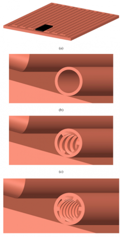
In the following year, Shahsavar et al. [58] continued their research on the effect of helical microchannel heat sink grooving on the Energy and Exergy performance of nanofluid-based PVT units. Specifically, the plain unit, parallel unit, and staggered unit are the three PVT units that are the subject of the current investigation. To improve heat transmission, Figure 10(b) depicts a view of a copper-based helical microchannel heat sink that has been attached to a solar panel using thermal grease. The fluid flow channel measures 0.4 mm in width and 2.5 mm in thickness, while the heat sink's overall thickness is 5 mm. Four symmetrical parts are arranged in a helical pattern to make up each heat sink. A 0.6 mm-wide intake channel allows nanofluid to enter the heat sink, and four outlets with an assumed diameter of 0.4 mm each allow it to leave.
The performance of PVT units based on nanofluids was studied, and two types of parallel and staggered grooves were taken into consideration. According to the data comparison, the staggered unit had an electrical energy efficiency of 12.36%, which was higher than the plain unit and parallel unit by a ratio of 3.34% and 2.07%. The value of improved electrical efficiency increases to 9.32%, 10.69%, and 12.98% for plain units, parallel units, and staggered units when nanofluid is used as the working fluid.
In the integration of PVT systems, the surface area of the collector in direct contact with the panel has the most significant influence, but the flow pattern is also crucial to consider. In some models presented, an increase in the surface area of contact is achieved without changing the commonly used flow pattern. Improvisation is made through the creation of fin bends that are integrated with the collector. Several fins are placed inside or outside the collector with different geometrical shapes. Through this modification, the surface area of contact can increase, and heat accumulation is not too concentrated in one place on the collector. However, the geometrical shape of some models used is highly complex with high detail, resulting in its manufacturing issues.
Computational Fluid Dynamics (CFD) is a method of using algorithms and numerical methods to simulate fluid behavior to solve problems related to fluids such as mass flow, motion and velocity, temperature distribution, and other related phenomena. CFD problem-solving is done with the help of computer program calculations. the modeling of fluid flow is based on the law of conservation of energy, mass, and momentum [59], that is:
6.1 Steady flow
Steady flow indicates the characteristics at each point in the fluid flow field that do not change with time [60].
$\frac{\partial \vec{V}}{\partial t}=0 ; \vec{V}=\vec{V}(x, y, z)$ (1)
6.2 Incompressible flow
The flow is said to be incompressible if the density of the fluid is constant, which means that there is no change in the value of the density along the flow. Air fluid is considered incompressible as long as the flow velocity is below 100 m/s [61]. Three-dimensional incompressible fluid flow can be expressed as follows:
$\frac{\partial \rho}{\partial t}=0 ; \rho=\rho(x, y, z)$ (2)
6.3 Continuity equation
In steady and incompressible flow, the amount of mass in the control volume is constant [59] and can be expressed as follows:
$\frac{\partial u}{\partial x}+\frac{\partial v}{\partial y}+\frac{\partial w}{\partial z}=0$ (3)
6.4 Navier-Stokes equation
This equation is the momentum equation for steady and incompressible flows.
$u \frac{\partial u}{\partial x}+v \frac{\partial u}{\partial y}+w \frac{\partial u}{\partial z}=-\frac{1}{\rho} \frac{\partial p}{\partial x}+v\left(\frac{\partial^2 u}{\partial x^2}+\frac{\partial^2 u}{\partial y^2}+\frac{\partial^2 u}{\partial z^2}\right)$ (4)
$u \frac{\partial v}{\partial x}+v \frac{\partial v}{\partial y}+w \frac{\partial v}{\partial z}=-\frac{1}{\rho} \frac{\partial p}{\partial y}+v\left(\frac{\partial^2 v}{\partial x^2}+\frac{\partial^2 v}{\partial y^2}+\frac{\partial^2 v}{\partial z^2}\right)$ (5)
$u \frac{\partial w}{\partial x}+v \frac{\partial w}{\partial y}+w \frac{\partial w}{\partial z}=-\frac{1}{\rho} \frac{\partial p}{\partial z}+v\left(\frac{\partial^2 w}{\partial x^2}+\frac{\partial^2 w}{\partial y^2}+\frac{\partial^2 w}{\partial z^2}\right)$ (6)
6.5 Energy equation
This equation describes the conservation of energy in the control volume of a steady and incompressible fluid flow. The equation governing the flow of incompressible fluid inside the collector is the equation of continuity, momentum, and energy. The following are the relevant expressions for this equation:
$\nabla \cdot \vec{V}=0$ (7)
$\frac{\partial \vec{V}}{\partial t}+(\vec{V} \cdot \nabla) \vec{V}=-\frac{1}{\rho} \nabla p+v \nabla^2 \vec{V}+\rho \vec{f}$ (8)
$\rho C_p\left[\frac{\partial T}{\partial t}+(\vec{V} \cdot \nabla) T\right]=k \nabla^2 T+\varphi$ (9)
where, refers to velocity vector (m/s), refers to overall force/mass (N/kg), refers to fluid density (kg/m3), refers to kinematic viscosity (m2/s), refers to temperature (K), refers to the thermal conductivity (W/mK), and refers to the viscosity dissipation which can be expressed as follows $\vec{V} \vec{f} \rho v T k \varphi$.
$\varphi=\left(\frac{\partial u}{\partial y}+\frac{\partial v}{\partial x}\right)^2+2\left[\left(\frac{\partial u}{\partial x}\right)^2+\left(\frac{\partial v}{\partial y}\right)^2\right]$ (10)
where, u and v refer to the component velocity in x and y, units (m/s).
6.6 Turbulence equation
The turbulence equation is used to model mathematically the effects of turbulence. The model used is the recommended Re-Normalization Group (RNG) k-ε model for modeling flow in air vents [62]. The equation for the turbulent kinetic energy (k) is as follows:
$\frac{\partial}{\partial \mathrm{t}}(\rho \mathrm{k})+\frac{\partial}{\partial \mathrm{x}_{\mathrm{i}}}\left(\rho \mathrm{ku}_{\mathrm{i}}\right)=\frac{\partial}{\partial \mathrm{x}_{\mathrm{j}}}\left[\left(\mu+\frac{\mu_{\mathrm{t}}}{\sigma_{\mathrm{k}}}\right) \frac{\partial \mathrm{k}}{\partial \mathrm{x}_{\mathrm{j}}}\right]+\mathrm{P}_{\mathrm{k}}-\rho \varepsilon$ (11)
The equation for the turbulent energy dissipation rate (ε) is as follows:
$\frac{\partial}{\partial t}(\rho \varepsilon)+\frac{\partial}{\partial x_i}\left(\rho \varepsilon u_i\right)=\frac{\partial}{\partial x_j}\left[\left(\mu+\frac{\mu_t}{\sigma_{\varepsilon}}\right) \frac{\partial \varepsilon}{\partial x_i}\right]+C_{1 \varepsilon} \frac{\varepsilon}{k} P_k-C_{2 \varepsilon}^* \rho \frac{\varepsilon^2}{k}$ (12)
where,
$C_{2 \varepsilon}^*=C_{2 \varepsilon}+\frac{C_\mu \eta^3\left(1-\frac{\eta}{\eta_0}\right)}{1+\beta \eta^3} ; \eta=\frac{S k}{\varepsilon} ; S=\left(2 S_{i j} S_{i j}\right)^{1 / 2}$ (13)
The CFD method in this study was carried out using the ANSYS Fluent program. This program can model convection heat transfer cases using the finite element method in closed systems, which means that the mass flow rate is constant and does not change with time. Steady-state modeling can be used to examine fluid flow in collector models. This program can also simulate solar radiation that works on solar cell models using ANSYS Steady State Thermal software. The research was conducted using ANSYS 18.2 workbench software for fluid flow and heat transfer in the studied PVT. The phenomenon of heat transfer between the layers of the PV cell and the fluid is modeled with ANSYS Fluent software, while ANSYS Thermal steady state software is only used to simulate the phenomenon of heat transfer from the natural convection of the PV cell layer. There is no simulation of solar radiant heat transfer, and only different heat fluxes are considered in the PV cell layer [63]. The CFD analysis geometric model was created using Solidworks 2018 software, and meshing was completed using ANSYS meshing software.
The ANSYS Fluent software uses steady-state simulations and the k-ε Re-Normalization Group (RNG) turbulence model. The mass flow rate of the input fluid can be varied with the input temperature, turbulence intensity of 5%, and the hydraulic diameter of the input collector area. The settlement method used is COUPLED Green Gauss Cell Based. The convergent criteria set are 10-6 for energy and 10-4 for pressure, velocity, and continuity equations.
Whereas in the ANSYS Steady State Thermal software, a steady state simulation is used. Solar radiation of 800 W/m2 is modeled by a heat flux (Q) module. Solar radiation is adjusted so that its direction hits the surface of the PV cell, while the other domain surfaces are affected by convection losses. Small heat transfer or convection loss (h) is considered to occur on the entire surface of the PV solar cell at 10 W/m2K [62]. A solid interface fluid is used on the top surface of the PV.
The numerical solution of the equations is carried out using a three-dimensional fluid dynamics computational model to predict the temperature distribution of the PV cell and water collector. For the declaration of boundary conditions as the only top surface of the PV cell exposed to heat flux. Therefore, only the outer layer of the PV cell is considered to receive stagnant heat flux and wind. The ambient temperature is constant during the simulation. For the water inlet boundary condition pressure is taken as 1 bar absolute pressure, and the outlet water condition is taken equal to the inlet pressure.
Due to the limitations of the tool in modeling solar radiation, the domain to be modeled, namely the fluid flowing behind the cell, and the boundary condition where the PV cell or collector has contact with the air must be adjusted according to the properties of the material making up the PV cell, as Figure 11. Fluid flows from the inlet and out towards the outlet to produce thermal fluid. The collector thickness is assumed to be 0 m in the Fluent simulation and is not affected by any other boundaries other than those specified [63].
Figure 11. Scheme of boundary condition simulation
Although there have been many reviews on the strategies for cooling photovoltaic panels and the application of nanofluids in PVT systems, there are still few reviews that specifically address this topic from a different perspective, with a focus on understanding the mechanisms for improving PVT performance overall. This article is expected to help researchers identify new and effective research gaps. In modeling the thermal collector design used, this study provides a comprehensive assessment of the latest developments in solar cooling technology for PVT systems. It should be noted that the arrangement of the thermal collector channels has a significant impact on PVT system performance. This article compares several PVT systems, including collector design configurations, fin integration on collector tubes, fin applications for PVT, and groove modeling on fin collectors. This study highlights the efforts of scientists around the world to improve PVT system performance and provides information on the application of renewable energy sources.
Great attention has been given to the discussion of the differences between active and passive cooling systems in PVT systems. Several studies have evaluated the performance of PVT systems based on the effect of thermal collector configuration and variations in the use of nanofluids in PVT system applications in detail. Literature suggests that the heat transfer process can be affected by the contact between the thermal collector and working fluid, as compared to PVT systems using conventional fluids. To find the ideal modeling, this article examines several essential elements such as nanofluid characteristics, mass flow rate, solar radiation, and collector geometry modeling that affect the cooling system.
To enhance the heat transfer process from photovoltaic panels, thermal collector modeling is performed with the aim of maximizing the surface area in contact with the panels. One commonly used method is integrating the thermal collector with fins or modifying the collector's design geometry to expand the contact surface without disturbing the working fluid flow inside the thermal collector. Several studies have shown that a larger contact surface between the working fluid and the collector can increase the heat absorption process from the photovoltaic panels. In designing the thermal collector, in addition to the contact surface area, other parameters such as losses, pressure drop, and environmental influences must be considered. The material, dimensions, and geometry of the thermal collector also need to be considered as they affect the thermal and electrical efficiency. Although some research sources are still in the form of simulated modeling, it is expected that this research will contribute to the development of more efficient, environmentally friendly, economical, and optimized PVT systems.
This research was conducted under the project titled "Development of Al2O3 Nanofluid-based Thermal Collector to Improve the Performance of Photovoltaic Solar Cells", with the Research Activity Implementation Contract Letter Main Contract No.: 160/E5/PG.02.00.PL/2023 and Derivative Contract No.: 1280.1/UN27.22/PT.01.03/2023. The project was generously funded by the Ministry of Education, Culture, Research, and Technology. The funding was allocated under the Doctoral Dissertation Research scheme for the Fiscal Year 2023.
[1] Kannan, N., Vakeesan, D. (2016). Solar energy for future world: - A review. 62: 1092-1105. https://doi.org/10.1016/j.rser.2016.05.022
[2] Prasetyo, S. D., Prabowo, A.R., Arifin, Z. (2022). The effect of collector design in increasing PVT performance: Current state and milestone. Materials Today: Proceedings, 63(Supplement 1): S1-S9. https://doi.org/https://doi.org/10.1016/j.matpr.2021.12.356
[3] Xiao, X., Zhang, P. (2013). Morphologies and thermal characterization of paraffin/carbon foam composite phase change material. Solar Energy Materials and Solar Cells, 117: 451-461. https://doi.org/10.1016/j.solmat.2013.06.037
[4] Kusuma, A.C., Harsito, C., Rachmanto, R.A., Arifin, Z. (2021). The effect of copper-aluminium perforated heat sink to improve solar cell performance. IOP Conference Series: Materials Science and Engineering, 1096(1): 012048. https://doi.org/10.1088/1757-899x/1096/1/012048
[5] Wanjiku, M., Kagiri, C., Maina, F., Mulembo, T. (2022). Photovoltaic thermal (PV/T) water heating system for energy efficiency optimization. In 2022 IEEE PES/IAS PowerAfrica, Kigali, Rwanda, pp. 1-4. https://doi.org/10.1109/PowerAfrica53997.2022.9905246
[6] Ren, H.S., Ma, Z.J., Lin, W.Y., Wang, S.G., Li, W.H. (2019). Optimal design and size of a desiccant cooling system with onsite energy generation and thermal storage using a multilayer perceptron neural network and a genetic algorithm. Energy Conversion and Management, 180: 598-608. https://doi.org/10.1016/j.enconman.2018.11.020
[7] Herrando, M., Pantaleo, A.M., Wang, K., Markides, C.N. (2019). Solar combined cooling, heating and power systems based on hybrid PVT, PV or solar-thermal collectors for building applications. Renewable Energy, 143: 637-647. https://doi.org/10.1016/j.renene.2019.05.004
[8] Chow, T.T., He, W., Ji, J. (2007). An experimental study of façade-integrated photovoltaic/ water-heating system. Applied Thermal Engineering, 27(1): 37-45. https://doi.org/10.1016/j.applthermaleng.2006.05.015
[9] Braun, R., Haag, M., Stave, J.L., Abdelnour, N. (2020). System design and feasibility of trigeneration systems with hybrid photovoltaic-thermal (PVT) collectors for zero energy office buildings in different climates. Solar Energy, 196(2020): 39-48. https://doi.org/10.1016/j.solener.2019.12.005
[10] Kant, K., Anand, A., Shukla, A., Sharma, A. (2020). Heat transfer study of building integrated photovoltaic (BIPV) with nano-enhanced phase change materials. Journal of Energy Storage, 30: 101563. https://doi.org/10.1016/j.est.2020.101563
[11] Jian, Y.F., Falcoz, Q., Neveu, P., Bai, F.W., Wang, Y., Wang, Z.F. (2015). Design and optimization of solid thermal energy storage modules for solar thermal power plant applications. Applied Energy, 139: 30-42. https://doi.org/10.1016/j.apenergy.2014.11.019
[12] Aste, N., Del Pero, C., Leonforte, F. (2012). Optimization of solar thermal fraction in PVT systems. Energy Procedia, 30: 8-18. https://doi.org/10.1016/j.egypro.2012.11.003
[13] Kubenthiran, J., Tijani, A.S., Akmad, M.S.B. (2021). Thermal Energy Recovery from Grid Connected Photovoltaic-Thermal (PVT) System Using Hybrid Nanofluid. In: Osman Zahid, M.N., Abdul Sani, A.S., Mohamad Yasin, M.R., Ismail, Z., Che Lah, N.A., Mohd Turan, F. (eds), Recent Trends in Manufacturing and Materials Towards Industry 4.0. Lecture Notes in Mechanical Engineering. Springer, Singapore. https://doi.org/10.1007/978-981-15-9505-9_72
[14] Aste, N., del Pero, C., Leonforte, F. (2014). Water flat plate PV-thermal collectors: A review. Solar Energy, 102: 98-115. https://doi.org/10.1016/j.solener.2014.01.025
[15] Joshi, S.S., Dhoble, A.S. (2018). Photovoltaic-Thermal systems (PVT): Technology review and future trends. Renewable and Sustainable Energy Reviews, 92: 848-882. https://doi.org/10.1016/j.rser.2018.04.067
[16] Tripanagnostopoulos, Y. (2007). Aspects and improvements of hybrid photovoltaic/thermal solar energy systems. Solar Energy, 81(9): 1117-1131. https://doi.org/10.1016/j.solener.2007.04.002
[17] Ceylan, I., Gürel, A.E., Demircan, H., Aksu, B. (2014). Cooling of a photovoltaic module with temperature controlled solar collector. Energy and Buildings, 72(2014): 96-101. https://doi.org/10.1016/j.enbuild.2013.12.058
[18] Gaur, A., Tiwari, G.N., Ménézo, C., Al-Helal, I.M. (2016). Numerical and experimental studies on a building integrated semi-transparent photovoltaic thermal (BiSPVT) system: Model validation with a prototype test setup. Energy Conversion and Management, 129: 329-334. https://doi.org/10.1016/j.enconman.2016.10.017
[19] Abdullah, A.L., Misha, S., Tamaldin, N., Rosli, M.A.M. (2018). Photovoltaic thermal /solar (PVT) collector (PVT) system based on fluid absorber design: A review. Journal of Advanced Research in Fluid Mechanics and Thermal Sciences, 48(2): 196-208.
[20] Prasetyo, S.D., Prabowo, A.R., Arifin, Z. (2022). Investigation of thermal collector nanofluids to increase the efficiency of photovoltaic solar cells. International Journal of Heat and Technology, 40(2): 415-422. https://doi.org/10.18280/ijht.400208
[21] Singh, S., Agrawal, S., Tiwari, A., Al-Helal, I.M., Avasthi, D.V. (2015). Modeling and parameter optimization of hybrid single channel photovoltaic thermal module using genetic algorithms. Solar Energy, 113: 78-87. https://doi.org/10.1016/j.solener.2014.12.031
[22] Alva, G., Liu, L.K., Huang, X., Fang, G.Y. (2017). Thermal energy storage materials and systems for solar energy applications. Renewable and Sustainable Energy Reviews, 68: 693-706. https://doi.org/10.1016/j.rser.2016.10.021
[23] Krishna, Y., Faizal, M., Saidur, R., Ng, K.C., Aslfattahi, N. (2020). State-of-the-art heat transfer fluids for parabolic trough collector. International Journal of Heat and Mass Transfer, 152: 119541. https://doi.org/10.1016/j.ijheatmasstransfer.2020.119541
[24] Arifin, Z., Tribhuwana, B.A., Kristiawan, B., Tjahjana, D.D.D.P., Hadi, S., Rachmanto, R.A., Prasetyo, S.D., Hijriawan, M. (2022). The effect of soybean wax as a phase change material on the cooling performance of photovoltaic solar panel. International Journal of Heat and Technology, 40(1): 326-332. https://doi.org/10.18280/ijht.400139
[25] Liu, Y., Meng, Q.Y., Yan, X.X., Zhao, S.Y., Han, J.Y. (2019). Research on the solution method for thermal contact conductance between circular-arc contact surfaces based on fractal theory. International Journal of Heat and Mass Transfer, 145: 118740. https://doi.org/10.1016/j.ijheatmasstransfer.2019.118740
[26] Das, D., Bordoloi, U., Kamble, A.D., Muigai, H.H., Pai, R.K., Kalita, P. (2021). Performance investigation of a rectangular spiral flow PV/T collector with a novel form-stable composite material. Applied Thermal Engineering, 182: 116035. https://doi.org/10.1016/j.applthermaleng.2020.116035
[27] Singh, P.L., Sarviya, R.M., Bhagoria, J.L. (2010). Thermal performance of linear Fresnel reflecting solar concentrator with trapezoidal cavity absorbers. Applied Energy, 87(2): 541-550. https://doi.org/10.1016/j.apenergy.2009.08.019
[28] Xiao, L., Gan, L.N., Wu, S.Y., Chen, Z.L. (2021). Temperature uniformity and performance of PV/T system featured by a nanofluid-based spectrum-splitting top channel and an S-shaped bottom channel. Renewable Energy, 167: 929-941. https://doi.org/10.1016/j.renene.2020.12.015
[29] Mohsenzadeh, M., Hosseini, R. (2015). A photovoltaic/thermal system with a combination of a booster diffuse reflector and vacuum tube for generation of electricity and hot water production. Renewable Energy, 78: 245-252. https://doi.org/10.1016/j.renene.2015.01.010
[30] Yu, Y., Yang, H., Peng, J., Long, E. (2019). Performance comparisons of two flat-plate photovoltaic thermal collectors with different channel configurations. Energy, 175: 300-308. https://doi.org/10.1016/j.energy.2019.03.054
[31] Ahmadi, R., Monadinia, F., Maleki, M. (2021). Passive/active photovoltaic-thermal (PVT) system implementing infiltrated phase change material (PCM) in PS-CNT foam. Solar Energy Materials and Solar Cells, 222: 110942. https://doi.org/10.1016/j.solmat.2020.110942
[32] Gelis, K., Ozbek, K., Celik, A.N., Ozyurt, O. (2022). A novel cooler block design for photovoltaic thermal systems and performance evaluation using factorial design. Journal of Building Engineering, 48: 103928. https://doi.org/10.1016/j.jobe.2021.103928
[33] Cheong Tan, W., Saw, L.H., Thiam, H.S., Yusof, F., Wang, C.T., Yew, M.C., Kun, M. (2019). Investigation of water cooled aluminium foam heat sink for concentrated photovoltaic solar cell. IOP Conference Series: Earth and Environmental Science, 268(1). https://doi.org/10.1088/1755-1315/268/1/012007
[34] Arifin, Z., Tjahjana, D.D.D.P., Hadi, S., Rachmanto, R.A., Setyohandoko, G., Sutanto, B. (2020). Numerical and experimental investigation of air cooling for photovoltaic panels using aluminum heat sinks. International Journal of Photoenergy, 2020: 1574274. https://doi.org/10.1155/2020/1574274
[35] Soliman, A.M.A., Hassan, H., Ookawara, S. (2019). An experimental study of the performance of the solar cell with heat sink cooling system. Energy Procedia, 162: 127-135. https://doi.org/10.1016/j.egypro.2019.04.014
[36] Mojumder, J.C., Ong, H.C., Chong, W.T., Leong, K.Y., Izadyar, N. (2017). An empirical analysis on photovoltaic thermal system with fin design by forced air circulation. Journal of Mechanical Science and Technology, 31(5): 2549-2557. https://doi.org/10.1007/s12206-017-0453-1
[37] Othman, M.Y., Yatim, B., Sopian, K., Bakar, M.N.A. (2007). Performance studies on a finned double-pass photovoltaic-thermal (PV/T) solar collector. Desalination, 209(1-3): 43-49. https://doi.org/10.1016/j.desal.2007.04.007
[38] Shrivastava, A., Jose, J.P.A., Borole, Y.D., Saravanakumar, R., Sharifpur, M., Harasi, H., Abdul Razak, R.K., Afzal, A. (2022). A study on the effects of forced air-cooling enhancements on a 150 W solar photovoltaic thermal collector for green cities. Sustainable Energy Technologies and Assessments, 49: 101782. https://doi.org/10.1016/j.seta.2021.101782
[39] Diwania, S., Agrawal, S., Siddiqui, A.S., Singh, S. (2020). Photovoltaic–thermal (PV/T) technology: A comprehensive review on applications and its advancement. International Journal of Energy and Environmental Engineering, 11(1): 33-54. https://doi.org/10.1007/s40095-019-00327-y
[40] Kumar, R., Rosen, M. (2011). Performance evaluation of a double pass PV/T solar air heater with and without fins. Applied Thermal Engineering, 31(8-9): 1402-1410. https://doi.org/10.1016/j.applthermaleng.2010.12.037
[41] Hussain, F., Anuar, Z., Khairuddin, S., Othman, M., Yatim, B., Ruslan, M.H., Sopian, K. (2012). Comparison study of air-based photovoltaic/thermal (PV/T) collector with different designs of heat exchanger. https://www.semanticscholar.org/paper/Comparison-study-of-air-based-photovoltaic-thermal-Hussain-Anuar/1f1de818111db0a80a19d0ac4342eb4e41405ec3.
[42] Othman, M.Y., Hussain, F., Sopian, K., Yatim, B., Ruslan, H. (2013). Performance study of air-based photovoltaic-thermal (PV/T) collector with different designs of heat exchanger. Sains Malaysiana, 42(9): 1319-1325.
[43] Jung, U.H., Kim, J.H., Kim, J.H., Peck, J.H., Kang, C.D., Choi, Y.S. (2016). Numerical investigation on the melting of circular finned PCM system using CFD & full factorial design. Journal of Mechanical Science and Technology, 30: 2813-2826. https://doi.org/10.1007/s12206-016-0541-7
[44] Hasan, A., McCormack, S.J., Huang, M.J., Norton, B. (2010). Evaluation of phase change materials for thermal regulation enhancement of building integrated photovoltaics. Solar Energy, 84(9): 1601-1612. https://doi.org/10.1016/j.solener.2010.06.010
[45] Huang, M.J. (2011). The effect of using two PCMs on the thermal regulation performance of BIPV systems. Solar Energy Materials and Solar Cells, 95(3): 957-963. https://doi.org/10.1016/j.solmat.2010.11.032
[46] Xu, H.J., Wang, Y., Han, X.C. (2020). Analytical considerations of thermal storage and interface evolution of a PCM with/without porous media. International Journal of Numerical Methods for Heat & Fluid Flow, 30(1): 373-400. https://doi.org/10.1108/HFF-02-2019-0094
[47] Simón-Allué, R., Guedea, I., Villén, R., Brun, G. (2019). Experimental study of phase change material influence on different models of photovoltaic-thermal collectors. Solar Energy, 190: 1-9. https://doi.org/https://doi.org/10.1016/j.solener.2019.08.005
[48] Ahmed, R., Nabil, K.A.I. (2017). Computational analysis of phase change material and fins effects on enhancing PV/T panel performance. Journal of Mechanical Science and Technology, 31(6): 3083-3090. https://doi.org/10.1007/s12206-017-0552-z
[49] Khodadadi, M., Sheikholeslami, M. (2021). Numerical simulation on the efficiency of PVT system integrated with PCM under the influence of using fins. Solar Energy Materials and Solar Cells, 233: 111402. https://doi.org/10.1016/j.solmat.2021.111402
[50] Masykur, Dwiyantoro, B.A. (2016). Experimental study of heat transfer characteristics of solar water heater collector with addition wavyfins on pipe. ARPN Journal of Engineering and Applied Sciences, 11(2): 957-961.
[51] Xu, H.T., Wang, N., Zhang, C.Y., Qu, Z.G., Karimi, F. (2021). Energy conversion performance of a PV / T-PCM system under different thermal regulation strategies. Energy Conversion and Management, 229: 113660. https://doi.org/10.1016/j.enconman.2020.113660
[52] Paradis, P.L., Rousse, D.R., Lamarche, L., Nesreddine, H. (2018). A hybrid PV / T solar evaporator using CO2: Numerical heat transfer model and simulation results. Solar Energy, 170: 1118-1129. https://doi.org/10.1016/j.solener.2018.06.015
[53] Tong, Y., Kim, J., Cho, H. (2015). Effects of thermal performance of enclosed-type evacuated U-tube solar collector with multi-walled carbon nanotube / water nano fluid. Renewable Energy, 83: 463-473. https://doi.org/10.1016/j.renene.2015.04.042
[54] Shahsavar, A., Jha, P., Arici, M., Kefayati, G. (2021). A comparative experimental investigation of energetic and exergetic performances of water/magnetite nanofluid-based photovoltaic/thermal system equipped with finned and unfinned collectors. Energy, 220: 119714. https://doi.org/10.1016/j.energy.2020.119714
[55] Shahsavar, A., Jha, P., Arıcı, M., Estellé, P. (2021). Experimental investigation of the usability of the rifled serpentine tube to improve energy and exergy performances of a nanofluid-based photovoltaic/thermal system. Renewable Energy, 170: 410-425. https://doi.org/10.1016/j.renene.2021.01.117
[56] Jha, P., Das, B., Gupta, R. (2019). Energy and exergy analysis of photovoltaic thermal air collector under climatic condition of North Eastern India. Energy Procedia, 158: 1161-1167. https://doi.org/10.1016/j.egypro.2019.01.299
[57] Shahsavar, A., Jha, P., Arıcı, M., Nižetić, S., Ma, Z.J. (2021). Energetic and exergetic performances of a nanofluid-based photovoltaic/thermal system equipped with a sheet-and-grooved serpentine tube collector: Indoor experimental tests. Solar Energy, 225: 918-933. https://doi.org/10.1016/j.solener.2021.08.005
[58] Shahsavar, A., Jha, P., Baniasad Askari, I. (2022). Experimental study of a nanofluid-based photovoltaic/thermal collector equipped with a grooved helical microchannel heat sink. Applied Thermal Engineering, 217: 119281. https://doi.org/10.1016/j.applthermaleng.2022.119281
[59] Al Kalbani, K.S., Alam, M.S., Rahman, M.M. (2016). Finite element analysis of unsteady natural convective heat transfer and fluid flow of nanofluids inside a tilted square enclosure in the presence of oriented magnetic field. American Journal of Heat and Mass Transfer, 3(3): 186-224. https://doi.org/10.7726/ajhmt.2016.1012
[60] Pritchard, P.J. (2011). Introduction to Fluid Mechanics, 8th Edition. Hoboken: John Wiley & Sons.
[61] Cengel, Y. (2013). Heat transfer: A practical approach. Journal of Chemical Information and Modeling, 53(9): 1689-1699.
[62] Popovici, C.G., Hudişteanu, S.V., Mateescu, T.D., Cherecheş, N.C. (2016). Efficiency improvement of photovoltaic panels by using air cooled heat sinks. Energy Procedia, 85: 425-432. https://doi.org/10.1016/j.egypro.2015.12.223
[63] Baranwal, N.K., Singhal, M.K. (2021). Modeling and Simulation of a Spiral Type Hybrid Photovoltaic Thermal (PV/T) Water Collector Using ANSYS. In: Baredar, P.V., Tangellapalli, S., Solanki, C.S. (eds), Advances in Clean Energy Technologies. Springer Proceedings in Energy. Springer, Singapore. https://doi.org/10.1007/978-981-16-0235-1_10