Monaem Elmnifi![]() | Ammar M. Al-Tajer
| Ammar M. Al-Tajer![]() | Hasan A. Al-Asadi
| Hasan A. Al-Asadi![]() | Mohammed Al Saker
| Mohammed Al Saker![]() | Laith J. Habeeb*
| Laith J. Habeeb*![]()
© 2023 IIETA. This article is published by IIETA and is licensed under the CC BY 4.0 license (http://creativecommons.org/licenses/by/4.0/).
OPEN ACCESS
Parabolic Trough Solar Collectors (PTCs) are crucial components in achieving high efficiency and thermal performance in thermoelectric power stations. This study presents a Computational Fluid Dynamics (CFD) simulation of a PTC with dimensions of 2 m × 1.5 m, incorporating a flat glass cover to safeguard the reflector's optical properties and the glass envelope from environmental factors such as dust, moisture, wind, and rain, resulting in improved thermal insulation and efficiency. A uniform temperature distribution at the Heat Collecting Element (HCE) level is assumed. A mathematical model is developed based on simplifying assumptions, and physical phenomena, including mass transfer, light, and heat, are simulated using mathematical equations derived from equilibrium equations and the optical behavior of materials (reflection, absorption, transmission). The model's validity is established through a comparison of simulation and computational results. The effects of PTC length, water mass flow, and solar tracking pattern on the water exit temperature are subsequently explored. This investigation enables the identification of optimal PTC dimensions and mass flow rates to meet the temperature requirements for various industrial and domestic applications, while maintaining high efficiency and thermal performance.
ANSYS simulation, CFD, heat collecting element, parabolic trough solar collector, photoelectric, solar energy, solid works program, thermal efficiency
The Sun, a significant energy source, emits 63 MW/m2 of energy in all directions. Earth receives approximately 1.7x10¹⁴ kW, with an energy flux density of around 1 kW/m2 on the planet's surface [1, 2]. This energy, estimated to be about 10,000 times the global energy demand, has been directly harnessed since ancient times for heating, obtaining fire, and drying plant and animal foods. With advancements in technology, solar energy collection mechanisms have evolved for water heating, space heating, crop drying, and cooking. Further development led to the conversion of solar energy into electricity either by photovoltaic conversion (PV) using solar cells or by thermal conversion in concentrating solar power (CSP) stations [3, 4].
Concentrating solar power stations (CSP) contribute 400 MW to global production and are projected to increase to approximately 20 GW by 2020 and 800 GW by 2050, preventing the emission of 321 million tons of CO2 per year in 2020 and 1.21 billion tons in 2050, according to the International Greenpeace Organization's "Solar Thermal Electricity 2016" report [5]. Among existing CSP technologies, parabolic trough collectors (PTC) are the most promising, cost-effective, and efficient alternative for electric power generation [6]. PTC plants account for 73.58% of total CSP capacity [7]. The working principle of PTCs is based on focusing direct solar radiation on the focal axis via a parabolic trough reflector, where the radiation is absorbed as heat by the absorber tube (copper or stainless steel with a selective surface). The heat is then transferred to the heat transfer fluid (HTF) flowing inside the absorber tube, providing thermal energy for the energy cycle through direct steam production or indirect heat transfer to a storage medium via heat exchangers [8].
Stoddard et al. study [8] suggested that solar energy from southern Mediterranean countries alone can meet the energy requirements of these countries and the rest of Europe's industrialized nations. After 1990, solar thermal energy applications expanded as clean and renewable energy sources, particularly with growing global awareness of environmental pollution hazards and the establishment of the Global Solar Program (1996-2005) approved by the 55th United Nations session through Resolution 53/7 [9].
Brooks et al. [9] developed small-scale commercial PTC units for use in the South African solar thermal program, with a collector length of 5 m and an aperture width of 1.5 m, and a cabinet flange (82°). Two configurations were compared: one with a vacuumed glass envelope and one without. Peak efficiencies were 55.2% and 53.8% for the first and second cases, respectively. Krüger et al. [10] investigated a PTC called "soliten PTC-1800" for water desalination, cooling, and electricity generation. Results showed relatively low heat losses and significant light losses, with proper operation at temperatures of 150℃-190℃. Smai and Zahi [11] considered PTC plants as the most practical indirect steam generation within solar thermal power stations, capable of providing thermal energy across a wide temperature range without significantly reduced thermal efficiency.
Scientists at the National Renewable Energy Laboratory (NREL) in the United States found that PTC power stations exhibit high efficiency, with steam produced at temperatures above 350℃ and a thermal efficiency of 73% during insolation hours, and an energy yield of around 1 kWh per 1 m2 [12]. The absorber tube was encased in a glass envelope to reduce heat losses. In 2013, Sagade et al. [13] observed a 29% increase in water exit temperature and a 68% increase in the water exit temperature difference in the presence of the glass envelope. Singh et al. [14] designed and manufactured a PTC without a glass envelope with an opening area of 21.44 m. The efficiency was 18.23% using an aluminum absorber tube, while the efficiency was 20.25% using a copper absorber tube. Ramchandra and Bhosale [15] used two types of reflectors: a mirror reflector and aluminum foil. The maximum temperature and efficiency of the PTC using the mirror reflector were 14% and 22% higher, respectively, than the aluminum foil case [16].
To improve efficiency, we propose adding a flat glass cover to the PTC collector's opening to protect the reflector's optical characteristics and the heat-collecting element (HCE) from dirt, dust, moisture, and rust. This addition enhances the absorber tube's thermal insulation, especially in the presence of wind, where convective loss transitions from natural to forced. In this paper, we investigate the effect of adding a flat glass cover to the PTC on the optical and thermal efficiencies, heat losses, and overall performance of the PTC system.
For the numerical calculation of PTC, we built a mathematical model based on simplistic assumptions for the study. Then simulate the physical phenomena (mass transfer, light, and heat) with mathematical equations based on equilibrium equations and the optical behavior of materials (reflection, absorption, transmission). Based on a reference study, For the PTC modeling adopted in the previous studies, then through the numerical solution of the total equations, we get the theoretical results, and then verify their validity by comparing them with the CFD program simulation results. One-dimensional analysis of 1D thermal transfer through (PTC) is adopted, and then balancing is prepared. Energy through partial differential equations, we consider that there is a uniformity in the temperature distribution at the level of the heat collecting element (HCE), and this is acceptable considering the glass envelope is not emptied of air [17]. Neglecting the thickness of the surfaces as being very small compared to the dimensions of (PTC). We consider heat transfer to be one-dimensional; that is, heat exchanges take place in the radial direction, and thus there is no difference between the different cross-sections of the heat-collecting element HCE, and the study of Forestall [18] indicated that this assumption is acceptable for PTC systems smaller than 100 m in length. Consider the system in a state of thermal stability. The absence of a phase change of water during the flow inside the absorbent tube Consider the optical and thermal properties of different materials (coefficients: reflection, absorption, transmittance, and thermal conductivity) independent of temperature. Ignore the heat transfer between the heat-collecting element HCE and its carrier supports and consider the heat transfer to the support structure through the conductive flat glass cover.
2.1 Thermal balancing of a model
Thermal balancing equations are written for all surfaces of PTC components based on the first law of thermodynamics:
${{\varnothing }_{st}}={{\varnothing }_{e}}-{{\varnothing }_{s}}+{{\varnothing }_{g}}$ (1)
where,
$\emptyset_{e_{-}}$Heat in flow
$\emptyset_{s_{-}}$Heat out flow
$\emptyset_{g_{-}}$Generative Heat Flow
$\emptyset_{st_{-}}$Stored Heat Flow
The amount of heat entering the collector is subtracted from the amount of heat leaving in addition to the heat produced.
2.2 Energy balance equation for fluid (HTF)
The fluid (HTF) receives heat from the absorbing tube through the heat exchange surface by forced convection according to the nature of the fluid flow (laminar or turbulent), to be stored by the fluid in the form of perceived heat (in the absence of phase change of the fluid), which leads to raising its temperature and we write an equation of balance:
${{\rho }_{\text{f}}}\times {{A}_{f}}\times C{{p}_{rf}}\frac{d{{T}_{f}}}{dt}={{h}_{\text{conv}\left( r\to f \right)}}\left( {{T}_{r}}-{{T}_{f}} \right)\pi \times D{{r}_{int}}$ (2)
where, is cross-sectional area of the inner absorbent tube:
${{A}_{f}}=\frac{\pi }{4}\overset{2}{\mathop{\text{ }\!\!~\!\!\text{ }D{{r}_{int}}}}\,~$ (3)
${{\rho }_{f}}\times \frac{D{{r}_{\text{int}}}}{4}\times C{{p}_{f}}\times \frac{d{{T}_{f}}}{dt}={{h}_{\text{conv }\!\!~\!\!\text{ }\left( r\to f \right)}}\left( {{T}_{r}}-{{T}_{f}} \right)~$ (4)
The heat transfer coefficient between the absorbent tube and the fluid (HTF) is given by:
${{\text{h}}_{\text{conv}\left( \text{r}\to \text{f} \right)}}=\frac{N{{u}_{\text{rf}}}{{\lambda }_{\text{f}}}}{\text{D}{{\text{r}}_{\text{i}}}}$ (5)
${{A}_{{{r}_{int}}}}=\pi \times {{D}_{{{r}_{i}}}}\times L~$ (6)
In the case of laminar flow $R e_D$≤2300, the Nusselt number is neither related to the Reynolds number nor to the Pyrantel number and is given [19]:
$N{{u}_{f}}=4.36$
In the case of turbulent and transitional flow for: 5.106≥$R e_D$≥2300 and 2000≥Pr≥0.5, the Nusselt number expression is given in the Gnielinski formula [20].
$\text{N}{{\text{u}}_{\text{f}}}=\frac{\left( {{\text{C}}_{f}}/2 \right)\left( R{{e}_{D}}-1000 \right)Pr}{1+12.7{{\left( {{C}_{f}}/2 \right)}^{\frac{1}{2}}}\left( P{{r}^{\frac{2}{3}}}-1 \right)}{{\left( \frac{Pr}{P{{r}_{w}}} \right)}^{0.11}}$ (7)
$R{{e}_{D}}=\frac{{{V}_{f}}\text{ }{{\rho }_{f}}\text{ }{{\text{D}}_{ri}}}{{{\mu }_{f}}}~$ (8)
The coefficient of friction Cf in the case of smooth tubes is calculated by the Filonenko relationship [21]:
${{C}_{f}}={{\left( 1.58\text{ ln R}{{\text{e}}_{D}}-3.28 \right)}^{-2}}$ (9)
2.3 Absorbent tube energy balancing equation
The absorbent tube receives the solar radiation after passing through the flat glass cover and then reflecting and then permeating from the glass envelope, to be stored in the form of heat, and the heat is transferred from it to the fluid by forced convection and to the glass envelope by convection and radiation. We write the balancing equation:
$~\begin{matrix} {{\rho }_{\text{r}}}{{A}_{r}}C{{p}_{r}}\frac{d{{T}_{r}}}{dt}=I{{C}_{g}}{{\tau }_{e}}{{\rho }^{\circ }}{{\tau }_{e}}{{\alpha }_{r}}\pi D{{r}_{ext}}+\left( {{h}_{conv\left( r\to e \right)}}+{{h}_{rad\left( r\to e \right)}} \right)\left( {{T}_{e}}-{{T}_{r}} \right)\pi D{{r}_{ext}} \\ +{{h}_{conv\left( r\to f \right)}}\left( {{T}_{f}}-{{T}_{r}} \right)\pi D{{r}_{int}} \\\end{matrix}~$ (10)
${{A}_{r}}=\frac{\pi }{4}\left( Dr_{ext}^{2}-Dr_{int}^{2} \right)$ (11)
The heat transfer between the absorbent tube and the glass cover is by free molecular convection when the glass cover is unloaded, where the pressure inside the cover is (P<1 mm Hg), and the heat transfer coefficient in this case is given by the study [18].
${{h}_{\text{conv}\left( \text{e}\to \text{r} \right)}}=\frac{{{\lambda }_{\text{g}}}}{\frac{{{\text{D}}_{{{\text{r}}_{\text{e}}}}}}{\sum {{\text{D}}_{\text{int}}}}+\text{bk}\left( \frac{{{\text{D}}_{\text{rint}}}}{{{\text{D}}_{{{\text{r}}_{\text{ext}}}}}}+1 \right)}~$ (12)
where, the constants b and k are given by the relations:
$b=\frac{\left( 2-a \right)\left( 9\gamma -5 \right)}{2a\left( \gamma +1 \right)}$ (13)
$k=\frac{2.331\times {{10}^{-20}}\left[ \left( \frac{{{T}_{r}}-{{T}_{e}}}{2} \right)+273.15 \right]}{P{{\delta }^{2}}}$ (14)
λg: the average heat transfer coefficient of the gas inside the glass cover under standard conditions at the average temperature between the absorbent tube and the cover glass (Wm-1 K-1):
k: mean free path of gas molecules inside the glass cover (m)
b: coefficient of mutual influence of molecules
a: The coefficient of the thermal position of the gas molecules, and its value ranges from 0.01 to 1, according to the viscosity of the gas [22] and in the case of the reaction (solid gas), it can be considered – (a=1) approximately [23, 24].
$\gamma$: the ratio of specific heat of the gas inside the envelope
P: pressure inside the envelope (mm Hg)
δ: the molecular diameter of the gas inside the cover glass (cm). For air, δ=3.66×10⁸ is given [25]. While the transfer is by free (natural) convection in the event that the envelope is not emptied of air, and the heat transfer coefficient in this case is given by the relationship [26]:
${{h}_{\text{conv}\left( \text{e}\to \text{r} \right)}}=\frac{2\pi \text{ }{{\lambda }_{\text{eff}}}\text{ L}}{\ln \frac{{{\text{D}}_{{{\text{r}}_{\text{int}}}}}}{{{\text{D}}_{{{\text{r}}_{\text{ext}}}}}}}$ (15)
${{\lambda }_{\text{eff}}}=0.386{{\lambda }_{a}}{{\left( \frac{{{P}_{{{r}_{a}}}}}{8\cdot 61+{{P}_{{{r}_{a}}}}} \right)}^{\frac{1}{4}}}{{\left( {{F}_{\text{cil}}}R{{a}_{a}} \right)}^{\frac{1}{4}}}$ (16)
${{F}_{\text{cil}}}=\frac{{{\left( \ln \left( \frac{D{{e}_{int}}}{{{D}_{{{r}_{ext}}}}} \right) \right)}^{4}}}{{{\left( \frac{D_{{{r}_{int}}}^{-D{{r}_{ext}}}}{2} \right)}^{3}}{{\left( D_{{{e}_{int}}}^{-3/5}+D_{{{r}_{ext}}}^{-3/5} \right)}^{5}}}$ (17)
$\lambda_{e f f}$: the effective heat transfer coefficient (Wm-1 K-1)
L: is the length of the absorbent tube (m)
$\lambda a$: the convective transfer coefficient of air at the average temperature between the glass envelope and the absorbent tube (Wm-1 K-1)
$F_{c i l}$: geometric shape modulus of two pivoting cylinders.
2.4 Energy balance equation for flat glass cover
The flat glass cover receives direct solar radiation, and exchanges heat with the glass envelope by natural convection and radiation, as well as with the atmospheric air surrounding the load, and with the sky by radiation, and with the metal support structure by conduction. The glass cover is transparent and of a small thickness so that it does not have an effect on reducing the temperature, but it helps in shortening the wavelength of the incident beam, which increases the global warming inside the complex. From the balancing equation:
$\begin{matrix} {{\rho }_{c}}{{e}_{c}}C{{p}_{c}}\frac{d{{T}_{c}}}{dt}=I{{\alpha }_{c}}+\left( {{h}_{\text{conv}\left( c\to e \right)}}+{{h}_{\text{rad}\left( c\to e \right)}} \right)\left( {{T}_{e}}-{{T}_{c}} \right)\left. +\left( {{h}_{\text{conv}\left( c\to amb \right)}}+ \right.{{h}_{\text{cond}\left( c\to \text{ }\!\!~\!\!\text{ support} \right)}} \right) \\ \begin{align} & \left( {{T}_{amb}}-{{T}_{c}} \right)+{{h}_{\text{rad}\left( e\to \text{ }\!\!~\!\!\text{ sky} \right)}}\left( {{T}_{\text{sky}}}-{{T}_{c}} \right)~ \\ & \\ \end{align} \\\end{matrix}$ (18)
The coefficient of heat transfer by convection with the surrounding air, which is related to the wind speed (v) and the width of the collector aperture (w), as well as the angle of incidence of solar radiation (I), is given [27]:
${{h}_{\text{conv}(c\to amb)}}=5.7+3.8v\text{ }+1.42{{\left( \frac{\left( {{T}_{C}}-{{T}_{\text{amb}}} \right)\sin \text{I}}{w} \right)}^{0.25}}$ (19)
The coefficient of heat transfer by radiation with the sky:
${{h}_{\text{r}ad\left( \text{c}\to \text{sky} \right)}}={{\varepsilon }_{\text{c}}}\sigma \left( {{\text{T}}_{\text{c}}}+{{\text{T}}_{\text{sky}}} \right)\left( \text{T}_{\text{c}}^{2}+\text{T}_{\text{sky}}^{2} \right)\frac{{{\text{T}}_{\text{c}}}-{{\text{T}}_{\text{sky}}}}{{{\text{T}}_{\text{c}}}-{{\text{T}}_{\text{a}}}}$ (20)
The temperature of the sky is given by the relationship:
${{T}_{\text{sky}}}=0.0552{{\left( {{T}_{a}} \right)}^{1.5}}$ (21)
It also calculates the temperature of the surrounding atmosphere:
${{T}_{\text{a}}}=\left[ \frac{{{\text{T}}_{\text{aMax}}}-{{\text{T}}_{\text{aMin}}}}{2} \right]\sin \left[ \frac{\left( \text{t}-8 \right)\pi }{12} \right]+\left[ \frac{{{\text{T}}_{\text{aMax}}}+{{\text{T}}_{\text{aMin}}}}{2} \right]$ (22)
where, TaMax and TaMin are the maximum and minimum ambient temperatures in the month under study, t is the time in hours.
2.5 Thermal yield of the solar collector
It is the ratio of the heat flux acquired by the fluid to the intensity of the solar radiation intercepted by the tube absorbent [28]. It is given by:
${{\eta }_{th}}=\frac{{{Q}_{u}}}{G\times {{A}_{ap\left( 1-{{A}_{f}} \right)}}}$ (23)
${{Q}_{u}}={{m}^{\circ }}\times {{C}_{pf}}\left( {{T}_{fo}}-{{T}_{fi}} \right)$ (24)
$G=I\times {{\rho }^{\circ }}\times {{\tau }_{c}}\times {{\tau }_{e}}\times {{\alpha }_{r}}\times \gamma $ (25)
${{\eta }_{\text{th}}}=\frac{{{m}^{\circ }}\times {{C}_{pf}}\left( {{T}_{fo}}-{{T}_{fi}} \right)}{G\times {{A}_{ap}}\left( 1-{{A}_{f}} \right)}$ (26)
${{Q}_{\text{loss}}}={{U}_{L}}\times {{A}_{r}}\left( {{T}_{r}}-{{T}_{a}} \right)$ (27)
where, UL: the average heat loss coefficient of the absorbent tube.
The system's total equilibrium equation is:
$I\times {{\rho }^{\circ }}\times {{\tau }_{c}}\times {{\tau }_{e}}\times {{\alpha }_{r}}\times \gamma \left( 1-{{A}_{f}} \right)w\times L={{Q}_{\mu }}+{{U}_{L}}\times {{A}_{r}}\left( {{T}_{r}}-{{T}_{a}} \right)$ (28)
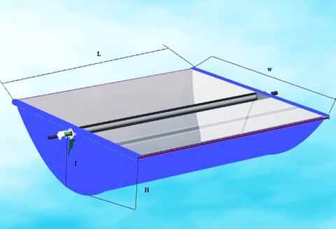
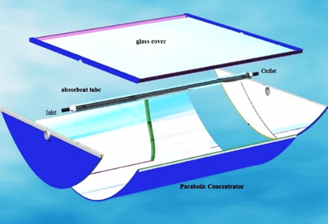
In the simulation setup, a parabolic trough collector of dimensions (2×1.5) with aperture area of 3 m2, focal length of 0.20 m, diameter of absorbent tube 25 mm, thickness of cover glass 3 mm is used for solar water heating. The schematic diagram of the parabolic trough collector as seen in Figure 1. The system consists of the following parts.
(a)
(b)
Figure 1. The schematic diagram of the Parabolic Trough Collector (PTC)
3.1 Reflector
It consists of a reflector in the form of a silvered glass mirror or polished aluminum or (INOX), where the reflection coefficient exceeds (88%), especially in the field of visible light, and it is installed longitudinally in a cylindrical shape so that its cross-section is a parabola, and the reflector material must maintain a coefficient of reflection for a long time under different weather and climatic conditions.
3.2 Heat Collecting Element (HCE)
The Heat Collecting Element (HCE) is located in the focal line of the parabolic reflecting surface, where it consists of an absorbent tube (usually copper or stainless steel), and its outer surface is coated with a selective layer to improve its optical properties (high visible light absorption + very weak emission coefficient of radiation infrared at high temperatures of the absorbing surface), thus absorbing a large part of the incoming solar radiation with a significant reduction in the loss of heat radiation emitted.
3.3 Heat Transfer Fluid (HTF)
The most common fluids are water, hydrocarbon oils, glycols, air, and molten salts. When choosing a Heat Transfer Fluid (HTF), the following criteria must be taken into account: the expansion coefficient is low; the viscosity coefficient is low; the heat capacity is high; the freezing point is low; and the boiling point is high.
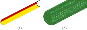
Figure 2. Geometry (a) and mesh (b) and of the model
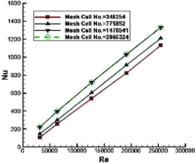
A schematic diagram of a proposed PTC design as seen in Figure 1. The stimulus area is 3 m2. The other dimensions are (2×1.5×0.7). The two-dimensional geometric model, boundary conditions, and unstructured mesh are illustrated in Figure 2. A mesh independence study was performed to ensure the accuracy of the numerical results. To find the most appropriate mesh size, the mesh-independent test is performed for four mesh (348254, 775852, 1478541, and 2965324 cells). The Nusselt number was estimated for all four mesh. Comparison of the results in Figure 3 shows that the mesh containing 1,478,541 retinal cells found is sufficient for the current study.
Figure 3. A comparative study of four different meshs
Relevant boundary terms are defined in all boundary terms to solve the continuity and momentum equations. Due to the large number of time steps and computer time limits, the 12-hour CFD simulation run time is required for PTC modeling. Incoming solar energy was considered constant over one hour (950 W/m2). The boundary conditions of the glass, bottom, and bottom factors were used as constant temperature limits. Starting at 9 a.m., the mean temperature was used as a limit condition until 8 p.m. In each one-hour period, the bottom temperature was determined to be similar to the glass temperature. The optical & thermal properties of the PTC components are given; the transmittance coefficient of the glass envelope & cover 0.935, the reflection coefficient of 0.935, the absorption coefficient of the selective surface (chrome black) 0.94, the specific heat capacity of water 4182 J/kg.K, the specific heat capacity of air 1,009 J/kg. The specific heat capacity of copper is 381 J/kg.K. The specific heat capacity of glass is 835 J/kg.K, the length of the collector is 2-20 m, and the flow rate of water is 0.02-0.25 kg/s.
Mathematical expression of the relevant boundary terms is:
I=950 W/m2, bottom temperature=glass temperature:
$\tau$=0.935
$\gamma$=0.935
α=0.94
Cpwater=4182 J/kg.K
Cvair=1009 J/kg
Cpcopper=381 J/kg.K
Cpglass=835 J/kg.K
L=2 - 20 m
Qu=0.2 - 0.25 kg/s
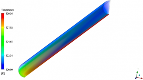
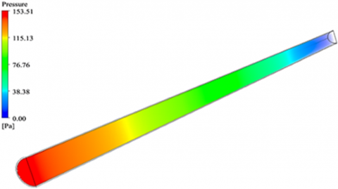
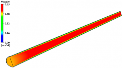
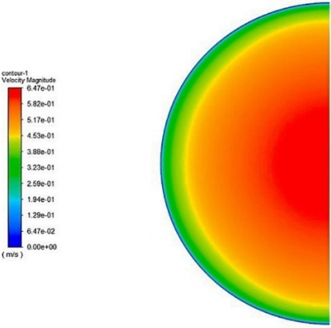
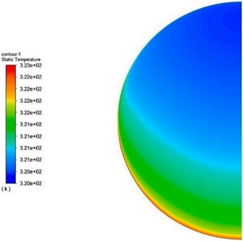
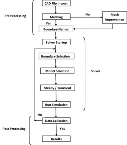
CFD analysis was performed utilizing the ANSYS application where parallel runs were used to solve the equations [29]. The computation time for each simulation required to reach a quasi-steady state was approximately 12 hours according to the computer used for the CFD simulation as the time step was 1 second. The objective of this paper is to introduce CFD modeling of heat transfer processes for a PCT. The water in the system is heated by solar energy. Gradually, the rate of hot water production increases until about 15:00 pm in summer and autumn. Then, by reducing solar radiation, the amount of hot water slowly decreases. Figures 4-8 show the simulation CFD results for the temperature, pressure, and velocity of the proposed PCT according to the boundary conditions. Building and mesh model engineering were performed using ANSYS Workbench 18 as shown in Figure 9.
Figure 4. The temperature PTC
Figure 5. The pressure PTC
Figure 6. The velocity PTC
Figure 7. The velocity PTC
Figure 8. The temperature PTC
Figure 9. Flow chart of CFD, specific process and steps of simulation
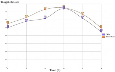
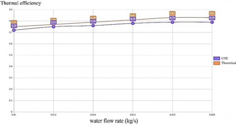
In order to confirm the results obtained based on the adopted mathematical model, we compared the thermal efficiency value during a typical day from sunrise to sunset obtained by simulation with the theoretical results, for the same conditions: The mass flow of fluid, collector dimensions, solar radiation, and the presence of the cover glass, as shown in Figures 10, and 11.
The theoretical results are almost identical to the simulation during the peak of the solar radiation, while the theoretical results are greater within 7% during the morning and evening as a result of the heat losses that we neglected part of in the simplistic assumptions of the mathematical model. Within the limits of the permissible errors, we confirm the validity of the results obtained through the simulation model in the study and through the computational results.
Figure 10. Comparison of theoretical and simulations thermal efficiency
Figure 11. Comparison of thermal efficiency at mass flow
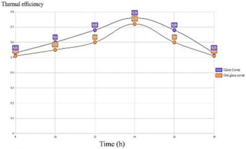
From Figure 12, the thermal efficiency starts at 0.51 and increases to the peak at demise, where the value of 0.76 is reached with the glass cover, In the presence of the glass cover, it leads to an increase in the thermal efficiency by a small percentage at the beginning of the day and then increases gradually until it reaches its demise. Its peak is 8%, to decline again after demise.
Figure 12. Thermal efficiency with cover glass effect
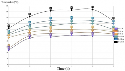
Figure 13 shows an increase in temperature at the beginning of the day, then its stability in the afternoon, then it declines in the evening. We also note that the temperature of stability increases with increasing length.
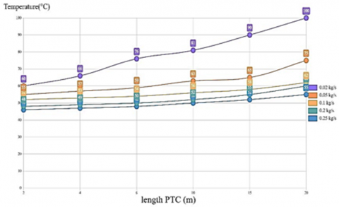
The fluid exit temperature increases with the increase in the length of the solar collector to increase the area of the opening and the increase in the heat exchange surface, while it decreases with the increase in the mass flow. Thus, the appropriate or the best length of the solar collector is determined by the mass flow and the temperature of the water required for use, as shown in Figure 14.
Figure 13. Water exit temperature with change in collector length
Figure 14. Variations in exit water temperature as a function of solar collector length and flow
In this paper, the design and realization of a model of a parabolic trough solar collector with the addition of a flat glass cover to the hole are presented for the purpose of increasing the thermal insulation and preserving the reflector's optical properties and the glass envelope's optical properties from deterioration due to moisture, rain, as well as dust and wind. Simulation was carried out using the CFD program for thermal and liquid effects. Then to expand the results, the program results were compared with the theoretical calculations of the (PTC) model. We obtained the effect of various factors (the length of the solar collector, the mass flow, the presence of the flat glass cover) on the exit water temperature and then the thermal efficiency. The glass cover of the PTC resulted in an 8% increase in thermal efficiency during the peak influx of solar radiation, and this is an addition provided by the cover to compensate for the decrease in efficiency due to weather conditions and changes.
[1] Kreith, F., Kreider, J.F. (1978). Principles of Solar Energy. McGraw-Hill, New York.
[2] Romero, M., Martinez, D., Zarza, E. (2004). Terrestrial solar thermal power plants: On the verge of commercialization. In Solar Power from Space-SPS'04, 567: 81.
[3] Abbas, G. (2010). Solar Energy Renewable Energy and the Environment. Taylor and Francis Group International Standard Book Number: 978-1-4200-7566-3 (Hardback).
[4] Soudani, M.E., Aiadi, K.E., Bechki, D., Chihi, S. (2017). Experimental and theoretical study of Parabolic trough collector (PTC) with a flat glass cover in the region of algerian sahara (Ouargla). Journal of Mechanical Science and Technology, 31: 4003-4009. https://doi.org/10.1007/s12206-017-0747-3
[5] Elmnifi, M. (2021). Using solar energy to build air conditioning-a case study of Libya. Global Journals of Research in Engineering, 21(A1): 25-31.
[6] Jenkins, P., Elmnifi, M., Younis, A., Emhamed, A., Amrayid, N., Alshilmany, M., Alsaker, M. (2019). Enhanced oil recovery by using solar energy: Case study. Journal of Power and Energy Engineering, 7(6): 57. https://doi.org/10.4236/jpee.2019.76004
[7] Soliman, A.M., Al-Falahi, A., Mohamed AEldean, S., Elmnifi, M. (2020). A new system design of using solar dish-hydro combined with reverse osmosis for sewage water treatment: case study Al-Marj, Libya. Desalination Water Treat, 193: 189-211.
[8] Stoddard, L., Abiecunas, J., O'Connell, R. (2006). Economic, energy, and environmental benefits of concentrating solar power in California (No. NREL/SR-550-39291). National Renewable Energy Lab. (NREL), Golden, CO (United States). https://doi.org/10.2172/881924
[9] Brooks, M.J., Mills, I., Harms, T. (2005). Design, construction and testing of a parabolic trough solar collector for a developing-country application. In Proceedings of the ISES Solar World Congress, Orlando, FL, 605: 6-12.
[10] Krüger, D., Pandian, Y., Hennecke, K., Schmitz, M. (2008). Parabolic trough collector testing in the frame of the REACt project. Desalination, 220(1-3): 612-618. https://doi.org/10.1016/j.desal.2007.04.062
[11] Smai, D.A., Zahi, M.L. (2016). Les potentialites de l’algerie en energies renouvelables. Recherches économiques et managériales, 19: 7902-1112.
[12] Price, H., Lu¨pfert, E., Kearney, D., Zarza, E., Cohen, G., Gee, R., Mahoney, R. (2002). Advances in parabolic trough solar power technology. Journal of Solar Energy Engineering, 124(2): 109-125. https://doi.org/10.1115/1.1467922
[13] Sagade, A.A., Aher, S., Shinde, N.N. (2013). Performance evaluation of low-cost FRP parabolic trough reflector with mild steel receiver. International Journal of Energy and Environmental Engineering, 4(1): 1-8. https://doi.org/10.1186/2251-6832-4-5
[14] Singh, S.K., Singh, A.K., Yadav, S.K. (2012). Design and fabrication of parabolic trough solar water heater for hot water generation. International Journal of Engineering Research & Technology, 1(10): 1-9.
[15] Ramchandra, H.P., Bhosale, S.K. (2016). The CFD analysis of solar parabolic trough system with reflectors. International Journal of Current Engineering and Technology, 5: 431-435.
[16] Pigozzo Filho, V.C., De Sá, A.B., Passos, J.C., Colle, S. (2014). Experimental and numerical analysis of thermal losses of a parabolic trough solar collector. Energy Procedia, 57: 381-390. https://doi.org/10.1016/j.egypro.2014.10.191
[17] Odeh, S.D., Morrison, G.L., Behnia, M. (1996). Thermal analysis of parabolic trough solar collectors for electric power generation. In Proceedings of ANZSES 34th annual conference, Darwin, Australia, pp. 460-467.
[18] Forristall, R. (2003). Heat transfer analysis and modeling of a parabolic trough solar receiver implemented in engineering equation solver (No. NREL/TP-550-34169). National Renewable Energy Lab., Golden, CO.(US). https://doi.org/10.2172/15004820
[19] Cengel, Y.A. (1997). Introduction to Thermodynamics and Heat Transfer (Vol. 846). New York: McGraw-Hill.
[20] Gnielinski, V. (1975). New equations for heat and mass transfer in the turbulent flow in pipes and channels. NASA STI/Recon Technical Report A, 41(1): 8-16.
[21] Kakaç, S., Shah, R.K., Aung, W. (1987). Handbook of single-phase convective heat transfer. United States.
[22] Saxena, S.C., Joshi, R.K. (1989). Thermal accommodation and adsorption coefficients of gases. United States.
[23] Trigg, G.L. (2005). Digital Encyclopedia of Applied Physics. Wiley.
[24] Zohar, Y. (2002). Heat Convection in Micro Ducts (Vol. 11). Springer Science & Business Media.
[25] Tjörnhammar, R., Edholm, O. (2014). Reparameterized united atom model for molecular dynamics simulations of gel and fluid phosphatidylcholine bilayers. Journal of Chemical Theory and Computation, 10(12): 5706-5715. https://doi.org/10.1021/ct500589z
[26] Raithby, G.D., Hollands, K.G.T. (1975). A general method of obtaining approximate solutions to laminar and turbulent free convection problems. Advances in Heat Transfer, 11: 265-315. https://doi.org/10.1016/S0065-2717(08)70076-5
[27] Norton, B., Kothdiwala, A.F., Eames, P.C. (1994). Effect of inclination on the performance of CPC solar energy collectors. Renewable Energy, 5(1-4): 357-367. https://doi.org/10.1016/0960-1481(94)90397-2
[28] Al-Madani, H. (2006). The performance of a cylindrical solar water heater. Renewable Energy, 31(11): 1751-1763. https://doi.org/10.1016/j.renene.2005.09.010
[29] Jassim, L., Elmnifi, M., Elbreki, A., Habeeb, L. (2021). Modeling and analysis of home heating system material performance with induction using solar energy. Materials Today: Proceedings, 61: 852-859. https://doi.org/10.1016/j.matpr.2021.09.302