Li Wah Thong*![]() | Swee Leong Kok
| Swee Leong Kok![]() | Roszaidi Ramlan
| Roszaidi Ramlan![]()
© 2023 IIETA. This article is published by IIETA and is licensed under the CC BY 4.0 license (http://creativecommons.org/licenses/by/4.0/).
OPEN ACCESS
Conventional piezoelectric cantilever beams experience limited operating bandwidth and reduced output power due to phase angle changes post-resonance. The phase shifting phenomenon between excitation and responses in piezoelectric cantilever beams is a critical factor in energy conversion efficiency. In this study, an equivalent circuit model for a multi-mode vibration energy harvesting system is presented, incorporating various electrical configurations to improve performance in terms of power output and bandwidth through phase shifting effects. The analytical modeling and experimental results of the proposed configurations demonstrate a significant increase in output power, particularly between intersections of successive peaks when the reverse polarity series connection is incorporated into the system. The phase difference between two cantilever beams is significantly reduced due to polarity changes, thereby boosting output voltage in the suggested configurations. The obtained frequency response output indicates that by alternating the polarities of the series connections in the vibration energy harvester, the output power between the valley of two successive frequencies at resonance for the energy harvesting system can be increased by up to 76 percent. This paper highlights the potential of leveraging phase shifting effects to optimize piezoelectric energy harvesting systems.
broadband energy harvesting, equivalent circuit model, multi-mode system, phase shift, piezoelectric cantilevers, single-degree-of-freedom
Vibration energy harvesting systems have become increasingly prevalent as alternatives to batteries in low-power applications, including wireless sensors, medical devices, and Internet of Things (IoT) technologies [1-3]. Resonance-based energy harvesters, particularly those utilizing cantilever structures, are favored due to their simple design and high output power density, enabling them to effectively power small electronic systems. However, the random and frequency-varying nature of ambient vibration sources, combined with the physical limitations of miniature cantilever structures, necessitates careful design and optimization of cantilever-based energy harvesters for practical applications [4, 5]. One major challenge in resonance-based harvesters is the ability to match the operating frequency of the cantilever beam with the surrounding vibration energy. Consequently, research efforts have been directed towards improving the system's performance, focusing on variations in design structures [6, 7], implementation of mechanical nonlinearities [8-10], and enhancements to electronic circuits [11, 12], all with the aim of increasing power output and efficiency.
Cantilever-based piezoelectric energy harvesters have been modeled as single-degree-of-freedom spring-mass-damper systems to estimate electrical output when vibrated at resonance frequencies. Researchers have developed transformer equivalent circuit models for these harvesters, consisting of a mechanical domain in the primary circuit and an electrical domain in the secondary circuit [13]. In contrast to single-degree-of-freedom models, cantilevered bimorph models with distributed parameters have demonstrated improved accuracy compared to experimental results for cantilevers without attached proof masses [14]. For cantilevers with attached proof masses, lumped parameter models remain applicable [15].
A significant factor affecting the performance of vibration energy harvesters is power loss due to phase variance between the excitation source and the frequency response of the cantilever beam [16]. As the frequency of the vibration source approaches the resonant frequency of the cantilever beam, the energy harvester experiences a 90° phase shift, reaching 180° beyond resonance. This results in an output voltage that lags or leads the input vibration by half a cycle, weakening the output signal response and yielding lower power output in a single cantilever system [17]. The reduction of power input due to these phase variances leads to inefficient energy harvesting systems. To address this issue, researchers have investigated multi-mode systems using arrays of cantilevers to increase the bandwidth of energy harvesting [18]. Recent studies have focused on utilizing arrays of piezoelectric cantilevers connected to external circuitry to achieve wider bandwidth energy harvesting [19, 20]. These external circuits typically consist of a rectifier, which converts the AC voltage generated by the cantilevers into DC voltage, and a large capacitor to minimize ripple effects in the output voltage. A variety of rectification circuits, including diode bridge rectifiers, AC-DC converters, Synchronized Switch Harvesting on Inductor (SSHI) techniques [21], and Synchronous Electric Charge Extraction (SECE) techniques [22], have been implemented successfully in energy harvesting systems. However, these techniques often face challenges such as impedance matching, inefficient diode conduction, and low sensitivity, leading to high energy loss and reduced system efficiency [23]. Furthermore, it has been observed that multi-cantilever systems can experience similar power loss due to phase shift phenomena, as seen in single cantilever systems [16].
In this paper, an equivalent circuit model is developed to investigate the performance of a multi-cantilever system for broadband vibration frequency harvesting without external circuitry. Various circuit configurations are analyzed to improve the multi-mode system's performance in response to phase variance effects. These configurations are compared to assess the impact of polarity changes on the series connections of each cantilever beam. A series of experiments is conducted to validate the proposed configurations for the energy harvesting system.
The remainder of this paper is organized as follows: Section 2 presents the theoretical analysis and motivation for using a multi-mode system in piezoelectric energy harvesting, as well as the equivalent circuit model and associated mathematical derivations. The significance of phase shifting between two piezoelectric cantilever beams for the system's power output response is also discussed, both mathematically and theoretically. Section 3 outlines the experimental design for validating the mathematical model. Finally, the paper concludes with a summary of the research findings and suggestions for future work.
2.1 Design and working mechanism
When two or more piezoelectric cantilevers are interconnected, possible electromechanical and electrical interactions can occur between the beams. The type of electrical connections employed for these piezoelectric cantilevers significantly influences the energy harvester's frequency response. Two common electrical configurations include series and parallel connections of the cantilevers. Researchers have demonstrated that series-connected cantilevers provide a wider operating bandwidth for the energy harvester, enabling the design of a multi-mode system [18].
A key focus of this research is the exploration of different polarity configurations when connecting cantilever beams in series, achieved through the manipulation of phase shifting effects in the beams. Polarity configuration refers to the various ways beams can be connected based on their voltage output orientation. The primary objective is to investigate how these different configurations impact the overall output power and efficiency of the system.
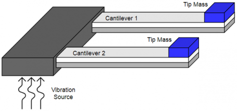
Figure 1 illustrates a sample configuration of two cantilever beams connected in an array. A vibration source is connected to both cantilever beams, providing a constant vibrational energy input for the entire system. For a multi-cantilever system to generate a broadband frequency spectrum, it is necessary to vary the resonance frequency of each cantilever beam. To address this challenge, proof masses of differing weights are attached to the tips of the cantilever beams, resulting in dissimilar resonance frequencies for each beam. As identical piezoelectric cantilever beams are utilized, they are assumed to possess the same electromechanical properties for the mathematical derivations. However, the total effective mass of each cantilever beam will differ due to the varying weights of the attached proof masses. The weights assigned to the cantilever beams are determined based on the desired resonant frequency of the vibration energy harvester. The total effective mass of an individual cantilever beam can be calculated as described in the study [24].
$m_{e f f}=\frac{33}{140} m_{\text {beam }}+m$ (1)
where, mbeam denotes the mass of the beam and m is the proof mass at the free-end tip of the cantilever beam. Using this equation, the weights for the tip mass is designed for the intended resonance frequency of each respective cantilever beams in the system.
Figure 1. Two cantilevers piezoelectric energy harvester
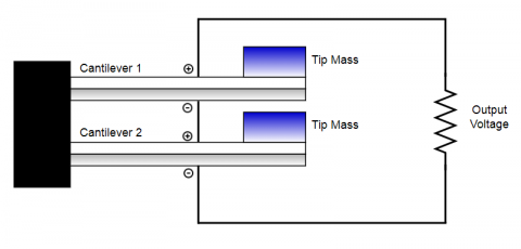
(a) Same polarity serial connection
(b) Reverse polarity serial connection
Figure 2. Different polarity configurations
In the design of the energy harvesting system using series configurations, two different connections at the output of the cantilever beam were proposed. Both of these configurations were able to produce different output frequency response curves and may be adaptable based on the design and requirements for a variety of applications. Figure 2 shows the two different polarity configurations, namely, same polarity serial connection and reverse polarity serial connection proposed in this paper. The same polarity serial connection configuration involves connecting the cantilever beams in series with their voltage outputs oriented in the same direction, while the reverse polarity serial connection involves connecting the cantilever beams in series with their voltage outputs oriented in opposite directions. Therefore, the output voltages of all the cantilever beams are either added or subtracted, depending on the phase shift phenomenon experienced by the cantilever beams throughout their operation for both configurations.
In the same polarity configurations, the negative side of the first cantilever will be connected to the positive side of the second cantilever while the opposite side of each beam will be connected to the load respectively, as illustrated in Figure 2(a). For the reverse polarity configurations, the negative side of the first cantilever will be connected to the negative side of the second cantilever while both the positive polarity will be attached to the resistor respectively, as shown in Figure 2(b). As each single piezoelectric cantilever beams experiences phase shift throughout its operation at different resonance frequency respectively, the overall system of the series configurations will also experience continuous phase changes due to their interconnection and substantial relationship with the excitation source. Thus, by altering the polarity of the connections, the frequency response and power output of the overall system may improve considerably. The resultant output power of the energy harvester is evaluated and compared using mathematical, numerical and experimental methods in this paper.
2.2 Equivalent circuit mathematical model
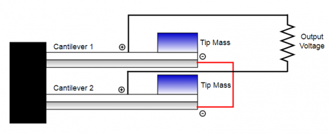
An analytical model for the broadband energy harvesting device is essential in this study on the effect of polarity connections for each cantilever. The equivalent circuit model can be applied to observe the explicit relationships between the cantilevers connections to achieve energy harvesting at a broader spectrum of frequency. Furthermore, optimal system performance can be obtained through optimization of the geometrical properties of the cantilevers by using the circuit model. The equivalent circuit model for the piezoelectric energy harvester of two cantilever beams attached using the same polarity serial configurations is as shown in Figure 3.
Figure 3. Model for same polarity serial connection
The properties of the piezoelectric cantilever beam are first modeled into both mechanical and electrical portions as equivalent circuit elements. The coupling effect with reference to the mechanical and electrical circuits was modeled using the properties of a transformer. The equivalent input voltage which is the stress caused by the external input vibration for each cantilever beams is represented respectively by
$\alpha_{i n(i)}=k_{a(i)} m_{(i)} \ddot{y}$ (2)
where, (i) indicates the selected cantilever beam, ka is a geometric constant that relates the stress of the external input vibration force on the piezoelectric material, m is the tip mass whereby the mass for each cantilever will differ respectively, and $\ddot{y}$ is the total input vibrations.
The corresponding resistance R, inductance L, and capacitance C in the mechanical portion of the circuit are characterize by the mechanical damping, mass, and mechanical stiffness of the energy harvester respectively and can be written as
$R_{(i)}=k_{a(i)} k_{b(i)} b_{m(i)}$ (3)
$L_{(i)}=k_{a(i)} k_{b(i)} m_{(i)}$ (4)
$C_{(i)}=\frac{1}{C_{e(i)}}$ (5)
where, kb is a geometric constant that relates the stress of the inertial force on the piezoelectric material, bm is the mechanical damping coefficient, and Ce is the elastic constant of the piezoelectric material.
The coupling effect is characterized electromechanically by the equivalent turns ratio of the transformer and is generally presented as
$N_{(i)}=\frac{a_{(i)} d_{31} C_{e(i)}}{2 t_{p(i)}}$ (6)
where, a is a constant determined by the internal wire connections of the piezoelectric material, d31 is the piezoelectric charge coefficients, and tp is the thickness of the piezoelectric material in the cantilever beam respectively.
The capacitor CB in the electrical domain of the circuit is the capacitance in the cantilever beams and is expressed as
$C_{B(i)}=\frac{w_{(i)}\ \varepsilon_{(i)}\ a_{(i)}^2\ l_{e(i)}}{2 t_{p(i)}}$ (7)
whereby, w is the width of the cantilever beam, ε is the dielectric constant of the material evaluated at constant stress, and leis the length of electrode covering the piezoelectric material on the cantilever beam respectively.
Applying Kirchoff’s law to the equivalent circuit for each cantilever beam, the sum of the voltages for the first cantilever beam can be express as
$\alpha_{i n 1}=R_1 \dot{S}+L_1 \ddot{S}+\frac{S}{C_1}+N_1 V_1$ (8)
$I_1=C_{B 1} \dot{V}_1+\frac{V_{L D}}{R_{L D}}$ (9)
where, S is the strain and $i_1$ is the current related to the strain and written as
$I_1=a_1 w_1 l_{e 1} d_{31} C_{e 1} \dot{S}$ (10)
The equivalent model for the first cantilever can now be derived by substituting Eqns. (8) and (9) with the respective variable to obtain the explicit relationship between strain and voltages and is represented by
$\ddot{S}+\frac{b_{m 1}}{m_1} \dot{S}+\frac{k_{s 1}}{m_1} S=\frac{a_1 d_{31} k_{s 1}}{2 t_{p 1} m_1}+\frac{\ddot{y}}{k_{b 1}}$ (11)
$\dot{S}=\frac{a_1 \varepsilon_1}{2 t_{p 1} d_{31} C_{e 1}} \dot{V}_1+\frac{V_{L D}}{a_1 w_1 l_{e 1} d_{31} C_{e 1} R_{L D}}$ (12)
where, ks1 is the equivalent spring constant applied in the model and defined as
$k_{s 1}=\frac{C_{e 1}}{k_{a 1} k_{a 2}}$ (13)
Carrying out the Laplace transform for both Eqns. (11) and (12) and solving them simultaneously, the output voltage for the first cantilever is expressed as
$\begin{gathered}{\left[\frac{2 t_{p 1} d_{31} C_{e 1} A_{i n}}{a_1 \varepsilon_1 k_{b 1}}\right]} \\ V_1=\frac{-\left[\frac{V_{L D}}{C_{b 1} R_{L D}}\right]\left[2 \varsigma_1 \omega_{n 1}+j\left(\omega-\frac{\omega_{n 1}^2}{\omega}\right)\right]}{j 2 \varsigma_1 \omega \omega_{n 1}+\omega_{n 1}^2\left(1-k_{31}^2\right)-\omega^2}\end{gathered}$ (14)
where, Ain is the Laplace transform of input vibration $\ddot{y}$, ωn1 is the resonant frequency of the first cantilever beam, ς1is the damping ratio applied in the lumped spring mass model, and k31 is the coupling coefficient of the piezoelectric material. Eq. (14) was also simplified using the substitutions of
$\frac{k_{s 1}}{m_1}=\omega_{n 1}^2$ (15)
$\frac{b_{m 1}}{m_1}=2 \varsigma_1 \omega_{n 1}$ (16)
$\frac{d_{31}^2 C_{e 1}}{\varepsilon_1}=k_{31}^2$ (17)
$s=j \omega$ (18)
Similarly, the same set of equations can be obtained for the second cantilever beam to solve for the output voltage, V2. For this research, each piezoelectric cantilever beams are assumed to have the same geometrical properties and the resonant frequency is differed by changing the proof mass at the free end of the cantilever beams respectively. Thus, the total voltage of the equivalent circuit model is found by taking the sum of the voltages for both cantilever beams and is further simplified as Eq. (19).
$V_{L D}=\frac{\left[\frac{2 t_p d_{31} C_e A_{i n}}{a \varepsilon k_b}\right] \sum_{i=1}^2\left(\gamma_i+j \beta_i\right)}{\prod_{i=1}^2\left(\gamma_i+j \beta_i\right)+\left(\frac{1}{\omega C_b R_{L D}}\right)}$
$\left[\sum_{h=1}^2\left(\beta_h+j \delta_h\right) \prod_{i=1, i \neq h}^2\left(\gamma_i+j \beta_i\right)\right]$ (19)
where
$\gamma_i=\omega_{n i}^2\left(1-k_{31}^2\right)-\omega^2$ (20)
$\beta_i=\beta_h=2 \varsigma \omega \omega_{n i}=2 \varsigma \omega \omega_{n h}$ (21)
$\delta_h=\omega^2-\omega_{n h}^2$ (22)
Subsequently, the average power output can be harvested and dissipated in the load resistor RL can be computed by
$P_{L D}=\frac{\left[V_{L D}\right]^2}{2 R_{L D}}$ (23)
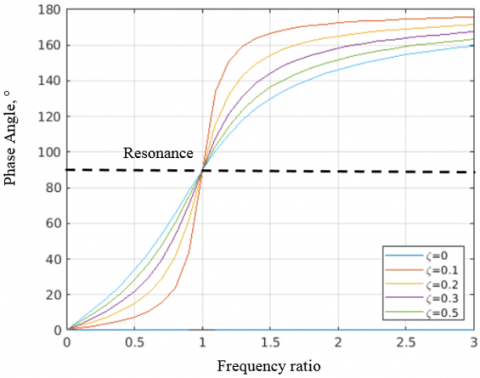
For the second configuration, similar serial configuration was applied in the system, however, the polarity of the second cantilever beam was reversed. This change of polarity connections was proposed to counteract the phase shifting phenomenon in the cantilever beams during resonance. Based on the theoretical findings, the phase angle of a piezoelectric cantilever beam will change throughout its operation in accordance with the changes of the frequency ratio between the operating frequency and its surrounding vibration. Generally, the piezoelectric cantilever beam experiences a phase shift of 90° at resonance irrespective of its damping ratio. Preceding to resonance, the system works in minimal change of phase angle and does not reflect polarity changes in the system. If the frequency of external vibration rises beyond the operating frequency of the cantilever beam, the phase angle tends to escalates to 180° of phase shift. This phase shifting effect was observed for all piezoelectric cantilever beams regardless of its changes in damping ratio ς, as illustrated in Figure 4.
Figure 4. Phase angle versus frequency ratio
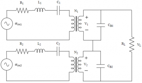
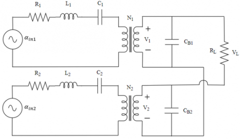
Adapting this principle of phase shifting in the energy harvesting system, this research proves that by reversing the polarity configuration of the cantilever beams in serial connection, the total power output of the energy harvester can upsurge substantially particularly at the range between two successive resonance frequencies. The operating bandwidth of the system can also be broadened when two or more cantilever beams are attached together in serial configurations. Figure 5 shows the proposed equivalent circuit model for the reversed polarity series configurations where the negative polarity of each cantilever beams is connected together while the load resistor is attached to the positive polarity of the beams.
Due to the change of voltage phase and polarity in the circuit configurations, the total output voltage can be taken as the difference between the voltages and further deduced as Eq. (24).
$\begin{aligned} & V_{L D} \\ & =\frac{\left[\frac{2 t_p d_{31} C_e A_{i n}}{a \varepsilon k_b}\right] \sum_{i=1}^N\left(\gamma_i+j \beta_i\right)}{\prod_{i=1}^N\left(\gamma_i+j \beta_i\right)+\left(\frac{1}{\omega C_b R_{L D}}\right)} \\ & {\left[\sum_{h=1}^N(-1)^{h-1}\left(\beta_h+j D_h\right) \prod_{i=1, i \neq h}^N\left(\gamma_i+j \beta_i\right)\right]} \\ & \end{aligned}$ (24)
Figure 5. Model for reverse polarity serial connection
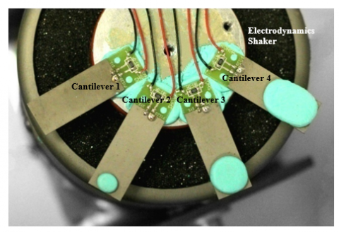
To validate the proposed configurations in optimizing the output response through phase shifting, a prototype was designed to observe the frequency response curves for both of the series configurations as demonstrated in Figure 6.
In this experiment, similar piezoelectric cantilever beams with same characteristics were applied and tip mass were placed at the free end of the beam to adjust its resonance frequency. Each of these individual cantilever beams were placed under the same electrodynamics shaker to record its resonance frequency. Identical cantilever beams were used in the experiment in order to warrant consistency of behavior and output for each beam throughout the operation. The piezoelectric cantilever beams that were applied in the system has the dimensions of 1.25 x 0.5 x 0.02 inch, with the weight of 2.3 grams.
Figure 6. Experimental setup of multi-cantilever system
One of the main requirements for extending the frequency bandwidth of the broadband energy harvester is to ensure that each cantilever beams in the system has a different resonance frequency. In order to incorporate the cantilever beams with different resonance frequencies, different weightage of proof mass of 0.15 grams, 0.50 grams and 1.00 grams was introduced for each piezoelectric cantilever beam respectively. Modeling clay with different weights were placed on the free end of the cantilever beam as the proof mass to adjust the resonance frequency of each beam. The tip mass was adjusted accordingly to ensure that each cantilever beams vibrates at its resonance frequency that differs from each other prominently. This is essential to create a broadband frequency energy harvester that will enable harvesting of vibration energy over a wide spectrum of frequency for better output. The distinctive fundamental frequency response of the cantilever shows that the modeling clay is effectively acting as a proof mass in tuning the operating frequency range of the cantilevers.
Each of these distinct cantilever beams was placed on an electrodynamic shaker that provides a constant vibration throughout its operation. The output voltage and its operating frequency was recorded at the matching resistor of 10 kΩ. Throughout the experiment, the multi-cantilever system was given excitation frequency of 10 Hz up to 500 Hz at constant acceleration level of 1-g (9.81 m/s2). The resultant frequency response output is then plotted accordingly for comparison and verification of its theoretical model.
4.1 Performance evaluation for same polarity series connected cantilever beams
Using the derivations of the mathematical equations for the equivalent circuit energy harvester, the output power for each cantilever beams with different resonance frequency and its total power in serial configurations were simulated using MATLAB software for verification and validation with the experimental output.
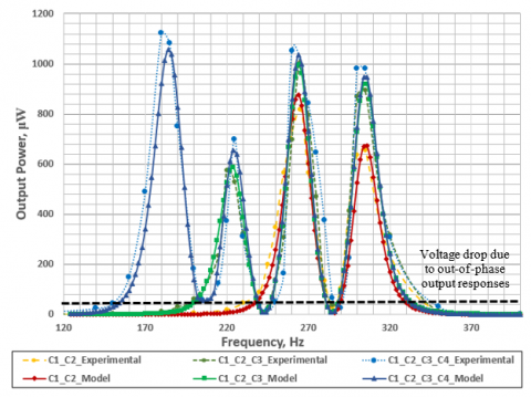
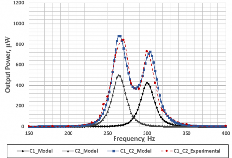
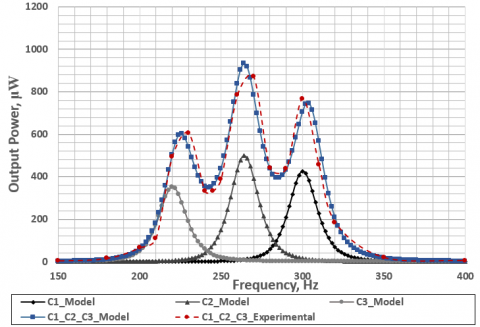
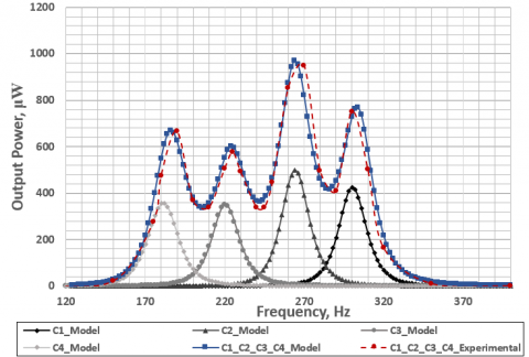
Figure 7 displays the frequency response curves in terms of power output when two, three and four piezoelectric cantilevers with different resonant frequencies are connected together as a multi-cantilever system using the same polarity in series configuration. It was observed that the power peaks as well as its operating bandwidth increases in accordance to the quantity of the cantilever beams. However, the output power decreases drastically at the valley between the resonant frequency of consecutive cantilever beams. This reduction in power is caused by the difference of phase angle induced by the respective cantilevers when it reaches the resonance frequency. When the first cantilever reaches resonance, the phase angle of the energy harvester upsurges to 180° causing it to be out-of-phase with the second cantilever’s output response. This undesired effect will indirectly affect the efficiency of the system. These resultant power output of the frequency response curves for this configuration ranging from two, three and four cantilever beams are found to be similar with the outcomes found in studies [24, 25].
Figure 7. Power output for same polarity series circuit
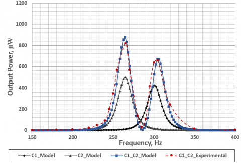
Figure 8. Power output for two same polarity beams
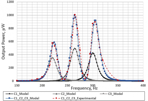
Figure 9. Power output for three same polarity beams
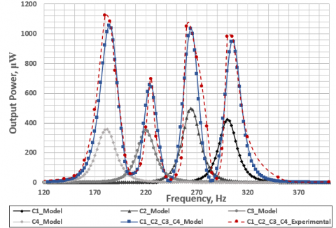
Figure 10. Power output for four same polarity beams
Figures 8-10 show the graphs of frequency response in terms of power output among the distinct cantilever beams and the multiple same polarity series connected cantilever beams ranging from two, three and four beams respectively. In terms of power output, the resultant power produced by two connected cantilever beams is prominently higher in comparison with the individual cantilever beam power output. For instance, at the second cantilever beam C2, the peak power for the series connected beam is at least 50 percent higher than its single cantilever beam power at the resonance frequency of 265Hz, as illustrated in Figure 8. However, the power output decreases below the frequency response of the single cantilever beam particularly at the valley and intersections between two resonance frequency output at the frequency of 285Hz. This reduction of power output after resonance for each cantilever beam is caused by the phase shift phenomenon during its operation. Correspondingly, as more cantilever beams were attached in the configurations, similar occurrences were observed at the peak and valley of the frequency response curves as shown in Figure 9 and Figure 10 respectively.
4.2 Performance evaluation for reverse polarity series connected cantilever beams
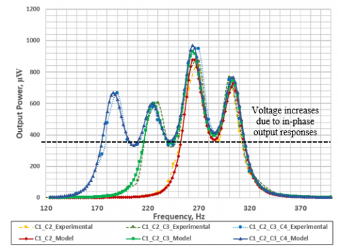
Figure 11 illustrates the frequency response curves in terms of power output when two, three and four piezoelectric cantilevers with different resonant frequencies are connected together as a multi-cantilever system using the alternating polarity series configuration. In comparison with the same polarity series connection, the output power produced was lowered by 10 to 15 percent, however, it is able to provide a more stable power output throughout the range of its operating frequency. Due to the cancellation of phase shifts between the output voltage of the individual cantilever beams in the reverse polarity configurations, the overall peak output voltage tends to be lower than the peak voltage of same polarity configurations. Additionally, the mechanical coupling between the cantilever beams in reverse polarity configurations may be significantly higher, causing some energy loss due to damping during its operation. Nonetheless, there were less fluctuations of power output especially between the peaks of the power and the system consistently provides similar output power peaks as the number of cantilever beams were increased accordingly.
Figure 11. Power output for reverse polarity series circuit
Figure 12. Power output for two reverse polarity beams
Figure 13. Power output for three reverse polarity beams
Figure 14. Power output for four reverse polarity beams
Figures 12-14 show the graphs of frequency response in terms of power output among the distinct cantilever beams and the multiple reverse polarity series connected cantilever beams. In the resultant graphs, the power output harvested by the multiple cantilever beams system can be at least 65 percent higher than its individual power output counterpart. The power output at the valley and intersections between two successive resonance frequency was also improved by at least 200 percent of its original power output.
As observed and evaluated from the resultant graphs for both the energy harvesting system with same polarity and reverse polarity series configuration, the phase shifting effect between two piezoeletric cantilever beams can be reduced by alternating the polarity electrical connection between them. This proposed methodology produces significant changes to the frequency response of the energy harvester in terms of reducing the ripple effect between two successive resonance frequencies of the cantilever beams. Through proper configurations of polarities connection for the cantilever beams in series connection, the total power output increases to almost double in comparison with the frequency responses of a single cantilever beam at its resonance frequency.
In this paper, this research has presented the analysis of equivalent circuit model with different polarity configuration on series connection for multi-mode cantilever beam system using mathematical, numerical and experimental methods. It has been shown that the phase shift that happens after the cantilever beam reaches resonance will cause a voltage drop in between two successive resonance frequency if the cantilever beams are attached in same polarity serial configurations. Therefore, it was proposed in this research to reverse the polarity of the second cantilever beam with the aim to position the output power of each cantilever beams to be in phase with each other. Both theoretical and experimental results prove that by alternating the polarity configurations in the series connection, the phase difference between the cantilevers can be reduced. This methodology may also be workable in nonlinear energy harvesting technologies using piezoelectric cantilever beams as the nonlinear system experiences the same phase shift conditions discussed in this research. Future work can be done to expand this model to verify its application in nonlinear system. Due to the intricate behavior of nonlinear systems in its operational phases, the proposed model could be enhanced to include nonlinear factors like hysteretic behavior, damping, and nonlinearities in the electromechanical structure. Additionally, the dynamic nonlinear characteristics of the softening and hardening effect in the piezoelectric cantilever beam can pose a challenge for the lumped-parameter models. Hence, modeling nonlinear systems necessitates more multifaceted mathematical methods as the occurrence of intricate phenomena such as bifurcations and chaos is relatively prevalent in the nonlinear system.
As a continuation of this research, similar methodology can be applied on a parallel circuit in order to identify its effect on the frequency response of the system. Moreover, further work on the impact of phase shifting effect for other non-linear energy harvesting circuit can be considered. Further improvement on the performance can also be done by optimizing the cantilever beams through material fabrication. Other parameters such as dimension of the cantilever beams and variability of cantilever beams arrangement can be studied accordingly for further enhancement of the energy harvesting system.
This work is supported by the Ministry of Higher Education Malaysia through Fundamental Research Grant Scheme (Grant number: FRGS/1/2020/TK0/MMU/03/13).
|
a |
dimensionless internal wire constant |
|
bm |
mechanical damping, N. s. m-1 |
|
C |
capacitance, F |
|
CB |
capacitance of bender, F |
|
Ce |
elastic constant, N. m2 |
|
d31 |
piezoelectric charge coefficients, C. N-1 |
|
I |
current, A |
|
ka |
geometric constant by input vibration, C.N |
|
kb |
geometric constant by inertial force, C.N |
|
ks |
equivalent spring constant, N. m-1 |
|
k31 |
piezoelectric coupling coefficient, C. N-1 |
|
L |
inductance, H |
|
m |
tip mass, g |
|
mbeam |
cantilever beam mass, g |
|
meff |
total effective mass, g |
|
N |
dimensionless equivalent turns ratio |
|
R |
resistance, Ω |
|
S |
dimensionless strain |
|
tp |
thickness of piezoelectric material, m |
|
V |
voltage, V |
|
w |
width of cantilever beam, m |
|
le |
length of electrode, m |
|
$\ddot{y}$ |
total input vibrations, m. s2 |
|
Greek symbols |
|
|
$\alpha$ |
voltage caused by external vibration, V |
|
β |
product of angular frequency, rad2. s-2 |
|
γ |
squared operating frequency, rad2. s-2 |
|
δ |
squared frequency difference, rad2. s-2 |
|
Ɛ |
dimensionless dielectric constant |
|
ω |
Angular frequency, rad. s-1 |
|
$\varsigma$ |
dimensionless damping ratio |
|
Subscripts |
|
|
i |
cantilever beam |
|
in |
input |
|
LD |
load |
|
n |
resonant |
[1] Ahmad, I., Hee, L.M., Abdelrhman, A.M., Imam, S.A., Leong, M.S. (2021). Scopes, challenges and approaches of energy harvesting for wireless sensor nodes in machine condition monitoring systems: A review. Measurement, 183: 109856. http://dx.doi.org/10.1016/j.measurement.2021.109856
[2] Famitafreshi, G., Afaqui, M.S., Melià-Seguí, J. (2021). A comprehensive review on energy harvesting integration in IoT systems from MAC layer perspective: Challenges and opportunities. Sensors, 21(9): 3097. http://dx.doi.org/10.3390/s21093097
[3] Hesham, R., Soltan, A., Madian, A. (2021). Energy harvesting schemes for wearable devices. International Journal of Electronics and Communications, 138: 153888. http://dx.doi.org/10.1016/j.aeue.2021.153888
[4] Manzoor, A., Rafique, S., Iftikhar, M.U., Hassan, K.M. U., Nasir, A. (2017). Study of piezoelectric vibration energy harvester with non-linear conditioning circuit using an integrated model. International Journal of Electronics, 104(8): 1317-1331. http://dx.doi.org/10.1080/00207217.2017.1296590
[5] Abdulsahib, I.A., Atiyah, Q.A. (2022). Vibration analysis of a symmetric double-beam with an elastic middle layer at arbitrary boundary conditions. Mathematical Modelling of Engineering Problems, 9(4): 1136-1142. http://dx.doi.org/10.18280/mmep.090433
[6] Sil, I., Mukherjee, S., Biswas, K. (2017). A review of energy harvesting technology and its potential applications. Environmental and Earth Sciences Research Journal, 4(2): 33-38. http://dx.doi.org/10.18280/eesrj.040202
[7] Zhou, S., Chen, W., Malakooti, M.H., Cao, J., Inman, D.J. (2016). Design and modeling of a flexible longitudinal zigzag structure for enhanced vibration energy harvesting. Journal of Intelligent Material Systems and Structures, 28(3): 367-380. http://dx.doi.org/10.1177/1045389X16645862
[8] Jiang, J., Liu, S., Feng, L., Zhao, D. (2021). A review of piezoelectric vibration energy harvesting with magnetic coupling based on different structural characteristics. Micromachines, 12(4): 436. http://dx.doi.org/10.3390/mi12040436
[9] Uzun, Y., Kurt, E. (2013). The effect of periodic magnetic force on a piezoelectric energy harvester. Sensors and Actuators A: Physical, 192: 58-68. http://dx.doi.org/10.1016/j.sna.2012.12.017
[10] Man, D.W., Xu, H.M., Xu, G.Z., Xu, D.H., Tang, L.P., Xu, Q.H. (2022). Dynamic characteristics analysis of tri-stable cantilever piezoelectric energy harvester with a novel-type dynamic amplifier. International Journal of Heat and Technology, 40(2): 619-626. http://dx.doi.org/10.18280/ijht.400232
[11] Lefeuvre, E., Badel, A., Brenes, A., Seok, S., Yoo, C.S. (2017). Power and frequency bandwidth improvement of piezoelectric energy harvesting devices using phase-shifted synchronous electric charge extraction interface circuit. Journal of Intelligent Material Systems and Structures, 28(20): 2988-2995. http://dx.doi.org/10.1177/1045389X17704914
[12] Liang, J. (2016). Synchronized bias-flip interface circuits for piezoelectric energy harvesting enhancement: A general model and prospects. Journal of Intelligent Material Systems and Structures, 28(3): 339-356. http://dx.doi.org/10.1177/1045389X16642535
[13] Tavares, R., Ruderman, M. (2020). Energy harvesting using piezoelectric transducers for suspension systems. Mechatronics, 65: 102294. http://dx.doi.org/10.1016/j.mechatronics.2019.102294
[14] Zhao, S., Erturk, A. (2013). Electroelastic modeling and experimental validations of piezoelectric energy harvesting from broadband random vibrations of cantilevered bimorphs. Smart Materials and Structures, 22(1): 015002. http://dx.doi.org/10.1088/0964-1726/22/1/015002
[15] Liao, Y., Liang, J. (2019). Unified modeling, analysis and comparison of piezoelectric vibration energy harvesters. Mechanical Systems and Signal Processing, 123: 403-425. http://dx.doi.org/10.1016/j.ymssp.2019.01.025
[16] Yang, Z., Erturk, A., Zu, J. (2017). On the efficiency of piezoelectric energy harvesters. Extreme Mechanics Letters, 15: 26-37. http://dx.doi.org/10.1016/j.eml.2017.05.002
[17] Covaci, C., Gontean, A. (2020). Piezoelectric energy harvesting solutions: A review. Sensors, 20(12): 3512. http://dx.doi.org/10.3390/s20123512
[18] Zhu, D., Tudor, M.J., Beeby, S.P. (2010). Strategies for increasing the operating frequency range of vibration energy harvesters: A review. Measurement Science and Technology, 21(2): 022001. http://dx.doi.org/10.1088/0957-0233/21/2/022001
[19] Qian, F., Liao, Y., Zuo, L., Jones, P. (2021). System-level finite element analysis of piezoelectric energy harvesters with rectified interface circuits and experimental validation. Mechanical Systems and Signal Processing, 151: 107440. http://dx.doi.org/10.1016/j.ymssp.2020.107440
[20] Wu, P.H., Lin, J.T., Lo, Y.C., Shu, Y.C. (2021). An SECE array of piezoelectric energy harvesting. Smart Materials and Structures, 30(4): 045008. http://dx.doi.org/10.1088/1361-665X/abe033
[21] Li, D., Wang, C., Cui, X., Chen, D., Fei, C., Yang, Y. (2022). Recent progress and development of interface integrated circuits for piezoelectric energy harvesting. Nano Energy, 94: 106938, http://dx.doi.org/10.1016/j.nanoen.2022.106938
[22] Costanzo, L., Lo Schiavo, A., Vitelli, M. (2022). Analytical study of piezoelectric harvesters with SECE and SSHI under variable excitation. IEEE Transactions on Industry Applications, 58(2): 2280-2290 http://dx.doi.org/10.1109/TIA.2022.3142664
[23] Brenes, A., Morel, A., Gibus, D., Yoo, C.S., Gasnier, P., Lefeuvre, E., Badel, A. (2020). Large-bandwidth piezoelectric energy harvesting with frequency-tuning synchronized electric charge extraction. Sensors and Actuators A: Physical, 302: 111759 http://dx.doi.org/10.1016/j.sna.2019.111759
[24] Dechant, E., Fedulov, F., Fetisov, L.Y., Shamonin, M., (2017). Bandwidth widening of piezoelectric cantilever beam arrays by mass-tip tuning for low-frequency vibration energy harvesting. Applied Sciences, 7(12): 1324. http://dx.doi.org/10.3390/app7121324
[25] Salem, M.S., Ahmed, S., Shaker, A., Alshammari, M.T., Al-Dhlan, K.A., Alanazi, A., Saeed, A., Abouelatta, M. (2021). Bandwidth broadening of piezoelectric energy harvesters using arrays of a proposed piezoelectric cantilever structure. Micromachines, 12(8): 973. http://dx.doi.org/10.3390/mi12080973