Dandun Mahesa Prabowoputra![]() | Purwanto*
| Purwanto*![]() | Sutini
| Sutini![]()
© 2023 IIETA. This article is published by IIETA and is licensed under the CC BY 4.0 license (http://creativecommons.org/licenses/by/4.0/).
OPEN ACCESS
Hydropower is a renewable energy source with a lot of potential in Southeast Asian countries, with a total energy potential of 152,257 MW in Southeast Asia. The development of a hydro-turbine design is required due to the enormous hydropower potential. The turbine's runner is critical for converting fluid internal energy into kinetic energy. A cross-flow turbine that has gained popularity recently is the banki-turbine. The research that has been done is three-dimensional modeling of the banki-turbine with the CFD method. This study aims to determine the effect of the blade's angle on turbine performance. This research's steps are design, mesh independence, validation, simulation, and analysis. Modeling research was conducted with variations of blade angles 10˚, 15˚, and 20˚. Schematic modeling using a steady state condition, the turbulent type Shear Stress transport (SST), and the tetrahedral mesh method. The modeling consists of a rotating zone and a stationary zone. The water inlet velocity is 3 m/s, and the outlet pressure equals the room pressure (1 atm). Simulation of banki-turbine operated in 50 RPM until 350 RPM of angular velocity. One of the analyzes used is Factorial Design. The best performance Cpmax is obtained from the variation of the blade's angle of 15˚ on 0.28.
banki-turbine, hydro-turbine, coefficient of power, factorial design, CFD, CFT
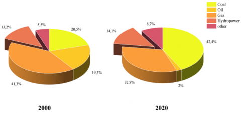
Southeast Asia is made up of countries with extensive aquatic areas. As shown in Table 1, the potential for hydro energy in Southeast Asian countries is enormous. The combined hydropower capacity of the four Southeast Asian countries is 152,275 MW [1]. Table 1 shows an excellent opportunity to develop hydropower plant technology. As shown in Figure 1, the development of hydropower technology will increase hydro energy's share of Southeast Asia's energy production mix, which is currently dominated by coal and gas. In 2000, hydropower accounted for 13.2% of the energy mix; by 2020, it is projected to account for 14.4% [2].
Table 1. Hydropower potential in Southeast Asian [1]
|
No. |
Country |
Hydropower potential |
|
1. |
Indonesia |
75,000 MW |
|
2. |
Malaysia |
22,500 MW |
|
3. |
Thailand |
15,155 MW |
|
4. |
Myanmar |
39,720 MW |
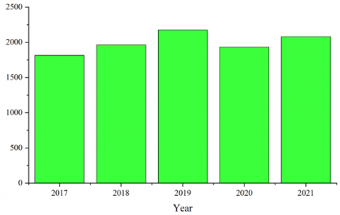
Hydropower is a clean energy source that can be converted into electrical energy. Figure 2 shows that the hydropower mix only increased by 1% in the past 20 years. One way to improve the Hydropower composition in electrical energy sources is to develop technology for converting hydropower into electrical energy. The component used in converting hydropower into electrical energy is a turbine. In this decade, research on water turbines has increased, both experimental study [3-5] and research modeling [6-8]. In addition, a number of scholarly articles that take the form of literature reviews have been written and published on the subject of hydro turbines [9-11]. Figure 2 shows the number of research on water turbines in the last five years tends to increase. The data was obtained from the commercial journal's index by searching for the keyword "hydro-turbine and water-turbine."
Figure 1. Energy mix in Southeast Asia in 2000 and 2020
Cross-Flow Hydro turbine based on “Driving Force” consists of drag force based configuration, lift forced based configuration, and hybrid configuration. A turbine with a drag force-based configuration has the advantage of good efficiency but lacks self-starting capability. An example of this type of cross-flow turbine is the Darrieus Rotor. The second type is a drag force-based configuration, where this rotor has the better self-starting capability but has low efficiency. Turbine with Hybrid configuration combines lift force and drag force, examples of the application of this type is darrieus rotor outside and savonius rotor inside; darrieus upside and savonius rotor downside; and darrieus downside and savonius rotor upside [12]. The Savonius turbine and the banki-turbine are quite popular turbines developed because they both have a simple shape and can be operated using air or water fluids. Changes in geometry are still the primary research to improve turbine performance, such as PSA [13], Aspect Ratio [14], Number of blades [8, 15], Overlap ratio [16], Number of stages [6], and shape of blade [3]. However, apart from the geometric aspect, several other factors also influence, such as the rotor material factor [17-20].
Figure 2. Histogram of increased research on hydro turbines
Investigations into the capabilities of the banki-turbine have been carried out. The method of computational fluid dynamics was utilized in order to conduct an investigation into the banki-turbine. Ansys Student version 2021 with the CFX solver was the modeling software that was utilized throughout this process. In this particular piece of research, a three-dimensional modeling process has been carried out making use of different blade angles on the runner. There are three different runner angles available: 10˚, 15˚, and 20˚. The purpose of this research is to determine how the angle of the blades affects the performance of a banki-turbine type water turbine (Cross-flow type) equipped with a runner that has 28 blades.
The banki-turbine is a type of cross-flow turbine. This turbine is suitable for use as a tool to convert kinetic energy into electricity in hydropower plants. The advantages of the banki-turbine are that it has a simple structure, produces stable performance at various discharge variations, and is easy to manufacture. Banki-turbine has a mechanical system characterized by the continuous rotation of a runner caused by water and the conversion of mechanical energy in the rotation into electrical energy through a generator [4]. Parameters that affect banki-turbine performance are the number of blades, diameter ratio, and blade design [7]. Research on changes in the blade’s shape that has been done can increase by 1%-7.3% the performance with a regular blade shape [20]. In another study, modifying the blade's shape increased the power coefficient by 7.23% [21].
The aerodynamic performance of the banki-turbine is shown by the value of the coefficient of power (Cp) and the coefficient of moment (Cm). Another non-dimensional parameter used is Tip Speed Ratio (TSR). The non-dimensional parameters are shown by Eqns. (1)-(3), as follows [22]:
$C_p=\frac{T \omega}{\frac{1}{2} \rho A V^3}=\frac{P_{\text {output }}}{P_{\text {available }}}$ (1)
$T S R=\frac{R \omega}{V}$ (2)
$C_m=\frac{T}{\frac{1}{2} \rho A R V^3}$ (3)
where, T is the torque produced by the banki-turbine, is the angular velocity; and A is the projection area of the turbine. TSR is a tip Speed ratio, where R is the turbine radius; and V is the fluid velocity.
An experimental study must be performed prior to conducting modeling research. The value obtained from modeling is then compared to empirical research; this comparison is known as the mean absolute error (MAE). Where MAE is represented by Eq. (4), the value of MAE can be in the range of 7% [23].
$M A E=\frac{1}{n} \sum_{i=1}^n\left|f_i-y_i\right|$ (4)
Factorial design is a type of analysis used in research to determine the effect of existing factors [24-27]. This research uses a factorial design analysis, with two variables considered: the rotational speed factor and the blade angle. We can conclude the significance of each factor and determine the interaction of the two factors using a factorial design. In order to draw conclusions from the factorial design analysis results, compare the F value of the results to the F value in the table based on the degrees of freedom for that factor. Eqns. (5)-(9) provide the basic calculations, which are then presented in Table 2 [24, 25]. For each effect, the sum of squares equation is in the research [24]:
$S S_A=\frac{1}{b n} \sum_{i=1}^a y_{i . .}^2-\frac{y_{\ldots}^2}{a b n}$ (5)
$S S_B=\frac{1}{a n} \sum_{j=1}^b y_{j . .}^2-\frac{y_{\ldots}^2}{a b n}$ (6)
$S S_{\text {Subtotal }}=\frac{1}{n} \sum_{i=1}^a \sum_{j=1}^b y_{i j . .}^2-\frac{y_{\ldots}^2}{a b n}$ (7)
$S S_{A B}=S S_{ {Subtotal }}-S S_A-S S_B$ (8)
$S S_E=S S_T-S S_{\text {Subtotal }}$ (9)
When referring to a research factor denoted by A and B, the notation "a" and "b" indicates the degree of freedom associated with that factor. The AB notation is used to estimate the interaction that occurs between factors A and B. After that, the outcomes of the calculations carried out based on Eqns. (5)-(7) are depicted in Table 1 [24].
Table 2. Presentation of factorial design [24]
|
Var |
SS |
DOF |
Mean Square |
F0 |
|
A |
SSA |
a-1 |
$M S_A=\frac{S S_A}{a-1}$ |
$F_0=\frac{M S_A}{M S_E}$ |
|
B |
SSB |
b-1 |
$M S_B=\frac{S S_B}{b-1}$ |
$F_0=\frac{M S_B}{M S_E}$ |
|
AB |
SSAB |
(a-1)(b-1) |
$M S_{A B}=\frac{S S_{A B}}{(a-1)(b-1)}$ |
$F_0=\frac{M S_{A B}}{M S_E}$ |
|
Error |
SSE |
Ab(n-1) |
$M S_E=\frac{S S_E}{a b(n-1)}$ |
|
|
Total |
SST |
Abn-1 |
|
|
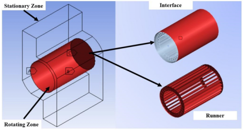
Research on banki-turbines with 28-blades was carried out using three-dimensional modeling. The research used Ansys student software with Solver CFX. Variations made are 10˚, 15˚, and 20˚ blade angles. The design and dimensions of the banki-turbine are shown in Figure 3. The banki-turbine has a height (H) of 130 mm, an outer diameter (D) of 80mm, an inner diameter (d) of 60mm, and a thickness of 2mm. The zones in the banki-turbine model are divided into two, a rotating zone and a stationary zone [8, 13, 15]. The rotating zone is the runner zone and the rotating interface, and the stationary zone is the runner's home zone and boundary conditions. Figure 4 shows the rotating zone and stationary zone. The rotating zone consists of an interface and a runner, while there are boundary and interface conditions in the stationary zone.
Figure 3. Design with variations in the angle of the blade
Figure 4. Rotating zone and stationary zone
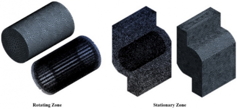
Meshing is carried out on this banki-turbine modeling using the Tetrahedral type [4]. Tetrahedral is applied to all modeling geometries, both rotating zones and stationary zones [28]. In the rotating zone, inflation is also applied to the rotor wall so that the mesh quality is better [29]. Figure 5 shows the resulting mesh in the rotating zone and stationary zone. Mesh independence is used to get the best meshing [13, 30]. Mesh independence is done by making changes to the mesh size [13]. There are five types of settings that have been created. The results of the independent mesh are shown in Figure 6. The mesh independence shows that the fifth size setting has good results, where there is no change in the value of torque [31]. Table 3 shows the value of mesh independence.
Figure 5. Mesh results for rotating zone and stationary zone
Figure 6. Graph of independent mesh results
Table 3. Mesh independence result
|
No |
Number of element |
Discrepancy |
|
1. |
990,774 |
|
|
2. |
990,796 |
0.5% |
|
3. |
990,895 |
1.0% |
|
4. |
990,965 |
0.1% |
|
5. |
990,991 |
0.1% |
Before taking data on the planned model, benchmarking has been done first. Benchmarking has been carried out on Makarim's research [31]. Figure 7 shows the benchmarking results between the modeling research carried out with Makarim's research. The error calculation uses equation 4 so that there is a difference of 6.33% between the research conducted and Makarim's research. An error or discrepancy of 6.33% in this modeling is acceptable because the limit used is less than 7% [23, 28, 30].
Figure 7. Benchmarking research using modeling with Makarim's research
The banki-turbine modeling is carried out in three dimensions in a steady state [7, 8]. The schematic of the modeling is shown in Figure 8. The turbulence type used in this study is SST [7, 8, 14]. This study uses the SST turbulence type because it has a higher error rate. Small compared to the K-epsilon type [7]. The inlet velocity of the water fluid is 3 m/s with a subsonic flow type and an output pressure of room pressure (1 atm). The wall in the modeling uses a no-slip wall boundary condition, and a wall roughness type used is a smooth wall. The outlet in the modeling uses opening conditions with the subsonic flow and uses 5% intensity on turbulence. The interface that connects the stationary zone with the rotating zone is fluid to fluid. The target residual in this study is 10-3. This model runs at an Angular Velocity of 50-350 RPM.
Figure 8. Schematic of the model
Research to determine the effect of the angle on the runner blade on the aerodynamic performance of the banki-turbine has been carried out using the computational fluid dynamics method. The results are the result of the resulting torque value, which is then converted to Cm. and power performance parameters using Eqns. (1)-(3). The results of these calculations are shown in Figure 9.
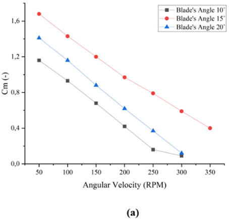
Figure 9. Graph a) coefficient of moment and b) coefficient of power
Figure 9 (a) shows a graph of the relationship between the coefficient of moment and the angular velocity. The graph shows the best performance coefficient of moment is the turbine tray with a runner angle of 15˚. The cmmax produced by the 10˚ runner is 1.16; runner 15˚ is 1.68; and runner 20˚ is 1.41. The results of Cm are shown in Figure 10.a is following the phenomenon in turbines in general, where the higher the angular velocity, the value of Cm will decrease. The worst Cm performance is shown on the banki-turbine with a blade angle of 10˚. In the graph, it can be seen that the angle of the blade influences the Cm generated by the banki-turbine.
The Coefficient of Power performance of the banki-turbine is shown by the graph of the relationship between Cp and Angular velocity in Figure 9 (b). The graph shows the best Cp produced by runners with blade's Angle 15˚. The second best performance was on the runner with a blade's angle of 20˚ and the worst on the runner with a blade's angle of 10˚. The cpmax produced by a runner with a blade's angle of 10˚ is 0.14, and that of a runner with a blade's angle of 20˚ is 0.18. the phenomenon of Cp on the blade's Angle 10˚ and 20˚ shows that Cpmax is produced at an angular velocity of 150 RPM. Cp continues to increase until the Angular velocity is 150 RPM, then Cp decreases at the next angular velocity. Runners who use a blade's angle of 15˚ produce a Cpmax of 0.28. Cpmax is generated at an angular velocity of 250 RPM. The calculation of the coefficient of power shows that the blade's angle affects the performance of the banki-turbine.
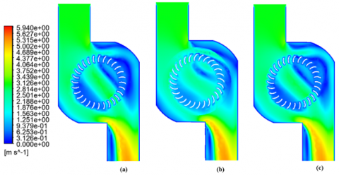
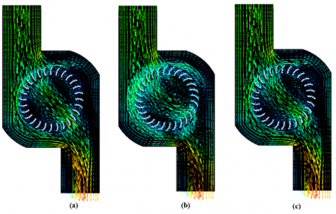
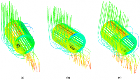
The velocity phenomenon in the banki-turbine modeling is shown in Figure 10, which shows the velocity contour, and Figure 11, which shows the velocity vector. In Figure 10, the contours displayed by each runner variation show almost the same pattern. The difference is seen in the size of the wake zone. The wake-zone on the blade's angle 15˚ variation is smaller than the others. The maximum speed produced by the blade's angle 15˚ is 5.24 m/s, while the blade's angle of 10˚ and 20˚ produces a maximum speed of 5.187 m/s and 5.188 m/s. The velocity vector in Figure 11 shows the same pattern in the same direction for all variations of the banki-turbine.
Figure 10. Velocity contours on a) Blade’ Angle 10˚, b) Blade’ Angle 15˚, and c) Blade’ Angle 20˚
Figure 11. Velocity vector on a) Blade’ Angle 10˚, b) Blade’ Angle 15˚, and c) Blade’ Angle 20˚
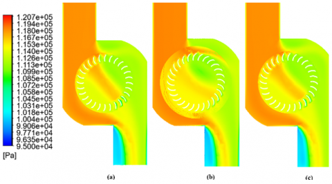
Figure 12. Pressure contour on a) Blade’ Angle 10˚, b) Blade’ Angle 15˚, and c) Blade’ Angle 20˚
Figure 12 shows the pressure contour in the fluid, while Figure 13 shows the pressure contour in the runner. Figure 12 shows that the runner with a blade's angle of 15˚ has a wider area of high pressure than the other variations. This phenomenon shows the correlation with the performance results shown in Figure 9. The maximum pressure generated by each rotor is 118.02 Pa (blade's angle 10˚), 118.74 Pa (blade's angle 15˚), and 118.5 (blade's angle 20˚). Figure 13 shows that the three runners have a contour equation, where the maximum pressure is in the area perpendicular to the fluid flow and has a low pressure at the endplate.
Figure 13. Pressure contour on runner body a) Blade’ Angle 10˚, b) Blade’ Angle 15˚, and c) Blade’ Angle 20˚
Table 4. The results of the factorial design analysis (two-factor) in the banki-turbine modeling
|
Variation |
SS |
DOF |
MS |
F0 |
|
Angular Velocity |
0.021 |
5 |
0.00 |
2.16 |
|
Blade's Angle |
0.057 |
2 |
0.03 |
14.64 |
|
Interaction |
0.000 |
1 |
0.000 |
0.02 |
|
Error |
0.018 |
9 |
0.0019 |
|
|
Total |
0.10 |
17 |
|
|
The analysis is strengthened using Factorial Design tools to determine the significance of the effect of blade angle. The factorial design used is a two-factor analysis [25, 26]. The factors in this study are the angular velocity and the blade's angle. Calculations using Eqns. (5)-(9) and Table 1. The results of the analysis carried out are shown in Table 4. The table shows F0 of the Angular velocity of 2.16 and F0 of the blade's angle of 14.64. F0 results show that the influence of the blade's angle is greater than the angular velocity, where the F0 value of the blade's angle is more significant. Then to find out the significance of each factor, is to compare the value of F0 in Table 3 with F0 in Table 5. Angular velocity has an insignificant effect on Cp performance, which is shown because F0 at angular velocity < F0 Table 5. Blade's angle has a significant impact indicated by the F0 > F0 table value. For the interaction between the two factors, based on the F0 comparison, the interaction shows that there is no interaction between the angular velocity factor and the Blade's Angle factor.
Table 5. F0 distribution value [24]
|
α= 0.05 |
|||
|
DOF |
v1 |
||
|
v2 |
1 |
2 |
5 |
|
17 |
4.45 |
3.59 |
2.81 |
The findings of a study that used three-dimensional modeling to determine the effect of blade angle on banki-turbine performance show that a runner with a blade angle of 15˚ Cpmax produces the best performance of 0.28. The angle of the blade was found to have a significant effect in a two-factor factorial design analysis. There is no interaction between the angular velocity factor and the angle of the blade, according to factorial design analysis. The velocity contours back up these findings, demonstrating that the 15˚ angle blade has a smaller wake zone and a wider high-pressure surface than the others. According to the findings of this study, the 15˚ angle of the blade can be used as an alternative design for the banki-turbine.
[1] International Energy Agency, Southeast Asia Energy Outlook 2022, IEA Publications, https://www.iea.org/reports/southeast-asia-energy-outlook-2022, accessed on Dec. 12, 2022.
[2] Nadhief, M.I., Prabowoputra, D.M., Hadi, S., Tjahjana, DDDP. (2020). Experimental study on the effect of variation of blade arc angle to the performance of Savonius water turbine flow in pipe. International Journal of Mechanical Engineering and Robotics Research, 9(5).
[3] Sinagra, M., Aric, C., Tucciarelli, T., Morreale, G. (2020). Experimental and numerical analysis of a back pressure Banki inline turbine for pressure regulation and energy production. Renewable Energy, 149: 980-986. https://doi.org/10.1016/j.renene.2019.10.076
[4] Xu, B.B., Luo, X.Q., Egusquiza, M., Ye, W., Liu, J., Egusquiza, E., Chen, D.Y., Guo, P.C. (2021). Nonlinear modal interaction analysis and vibration characteristics of a francis hydro-turbine generator unit. Renewable Energy, 168: 854-864. https://doi.org/10.1016/j.renene.2020.12.083
[5] Prabowoputra, D.M., Hadi, S., Prabowo, A.R., Sohn, J.M. (2020). Performance investigation of the Savonius horizontal water turbine accounting for stage rotor design. International Journal of Mechanical Engineering and Robotics Research, 9(2): 184-189. https://doi.org/10.18178/ijmerr.9.2.184-189
[6] Leguizamon, S., Avellan, F. (2020). Computational parametric analysis of the design of cross-flow turbines under constraints. Renewable Energy, 159: 300-311. https://doi.org/10.1016/j.renene.2020.03.187
[7] Purwanto, Budiono, Hermawan, Prabowoputra, D.D.M. (2022). Simulation study on cross flow turbine performance with an angle of 20° to the variation of the number of blades. International Journal of Mechanical Engineering and Robotics Research, 11(1): 31-36. https://doi.org/10.18178/ijmerr.11.1.31-36
[8] Karre, R.K., Srinivas, K., Mannan, K., Prashanth, B., Ch Prasad, R. (2022). A review on hydro power plants and turbines. AIP Conference Proceedings, 2418(1): 030048. https://doi.org/10.1063/5.0081709
[9] Prabowoputra, D.M., Prabowo, A.R. (2022). Effect of geometry modification on turbine performance: mini-review of Savonius rotor. International Journal of Mechanical Engineering and Robotics Research, 11(10): 777-783. https://doi.org/10.18178/ijmerr.11.10.777-783
[10] Quaranta, E., Perrier, J.P., Revelli, R. (2022). Optimal design process of crossflow Banki turbines: Literature review and novel expeditious equations. Ocean Engineering, 257: 111582. https://doi.org/10.1016/j.oceaneng.2022.111582
[11] Kamal, M.Mu., Saini, R.P. (2022). A review on modifications and performance assessment techniques in cross-flow hydrokinetic system. Sustainable Energy Technologies and Assessments, 51: 101933. https://doi.org/10.1016/j.seta.2021.101933
[12] Prabowoputra, D.M., Prabowo, A.R. (2022). Effect of the Phase-Shift Angle on the vertical axis Savonius wind turbine performance as a renewable-energy harvesting instrument. Energy Reports, 8(9): 57-66. https://doi.org/10.1016/j.egyr.2022.06.092
[13] Saad, A.S., Ookawara, S., Ahmed, M. (2022). Influence of varying the stage aspect ratio on the performance of multi-stage Savonius wind rotors, Journal of Energy Resources Technology, 144(1): 011301. https://doi.org/10.1115/1.4050876
[14] Prabowoputra, D.M., Prabowo, A.R., Hadi, S., Sohn, J.M. (2020). Performance assessment of water turbine subjected to geometrical alteration of Savonius rotor. Proceedings of the 6th International Conference and Exhibition on Sustainable Energy and Advanced Materials. Lecture Notes in Mechanical Engineering. Springer, Singapore. https://doi.org/10.1007/978-981-15-4481-1_35
[15] Al-Ghriybah, M., Zulkafli, M.F., Didane, D.H. (2020). Numerical investigation of inner blade effects on the conventional Savonius rotor with external overlap. Journal of Sustainable Development of Energy, Water and Environment Systems, 8(3): 561-576. https://doi.org/10.13044/j.sdewes.d7.0292
[16] Prabowo, A.R., Prabowoputra, D.M. (2020). Investigation on Savonius turbine technology as harvesting instrument of non-fossil energy: Technical development and potential implementation. Theoretical & Applied Mechanics Letters, 10(4): 262-269. https://doi.org/10.1016/j.taml.2020.01.034
[17] Quaranta, E., Perrier, J.P., Revelli, R. (2022). Optimal design process of cross-flow Banki turbines: Literature review and novel expeditious equations. Ocean Engineering, 257: 111582. https://doi.org/10.1016/j.oceaneng.2022.111582
[18] Prabowoputra, D.M., Prabowo, A.R., Bahatmaka, A., Hadi, S. (2020). Analytical review of material criteria as supporting factors in horizontal axis wind turbines: Effect to structural responses. Procedia Structural Integrity, 27: 155-162. https://doi.org/10.1016/j.prostr.2020.07.021
[19] Rio, J.S.D., Galvis-Holguin, S., Hincapié-Zuluaga, D., Arrieta, E.L.C. (2020). Effect of hydrodynamically designed blades on the efficiency of a michell-Banki turbine. International Journal of Renewable Energy Research, 10(3). https://doi.org/10.20508/ijrer.v10i3.10939.g7990
[20] Galvis-Holguin, S., Rio, J.S.D., Hincapié-Zuluaga, D. (2022). Enhancement efficiency of Michell-Banki turbine using NACA 6512 modified blade profile via CFD. EUREKA: Physics and Engineering, 2: 55-67. https://doi.org/10.21303/ 2461-4262.2022.002351
[21] Wu, K.T., Lo, K.H., Kao, R.C., Hwang, S.J. (2022). Numerical and experimental investigation of the effect of design parameters on Savonius-type hydrokinetic turbine performance. Energies, 15(5): 1856. 1856.https://doi.org/10.3390/en15051856
[22] Tahani, M., Rabbani, A., Kasaeian, A., Mehrpooya, M. Mirhosseini, M. (2017). Design and numerical investigation of Savonius wind turbine with discharge flow directing capability. Energy, 130: 327-338. https://doi.org/10.1016/j.energy.2017.04.125
[23] Prabowoputra, D.M., Sartomo, A., Suyitno. (2020). The effect of pressure and temperature on biodiesel production using castor oil. AIP Conference Proceedings, 2217: 030051. https://doi.org/10.1063/5.0000504
[24] Montgomery, D.C. (2017). Design and Analysis of Experiments. John Wiley & Sons.
[25] Sartomo, A., Prabowoputra, D.M., Suyitno. (2020). Factorial design of the effect of reaction temperature and reaction time on biodiesel production. AIP Conference Proceedings, 2217: 030052. https://doi.org/10.1063/5.0000505
[26] Rueda-Bayona, J.G., Paez, N., Eras, J.J.C., Gutiérrez, A.S. (2022). DOE-ANOVA to optimize hydrokinetic turbines for low velocity conditions. Mathematical Modelling of Engineering Problems, 9(4): 979-988. https://doi.org/10.18280/mmep.090415
[27] Prabowoputra, D.M., Prabowo, A.R., Hadi, S., Sohn, J.M. (2020). Assessment of turbine stages and blade numbers on modified 3D Savonius hydrokinetic turbine performance using CFD analysis. Multidiscipline Modeling in Materials and Structures, 17(1): 253-272. https://doi.org/10.1108/MMMS-12-2019-0224
[28] Agarwal, A. (2022). Computational investigation of vertical axis wind turbine in hydrogen gas generation using PEM electrolysis. Journal of New Materials for Electrochemical Systems, 25(3): 172-178. https://doi.org/10.14447/jnmes.v25i3.a03
[29] Venkatesan, S.P., Kumar, V.P., Kumar, M.S., Kumar, S. (2018). Computational analysis of aerodynamic characteristics of dimple airfoil NACA 2412 at various angles of attack. International Journal of Mechanical Engineering and Technology, 9(9): 41-49.
[30] Prabowoputra, D.M., Prabowo, A.R., Hadi, S., Sohn, J.M. (2020). The effect of multi-stage modification on the performance of Savonius water turbines under the horizontal axis condition. Open Engineering, 10(1): 793-803. https://doi.org/10.1515/eng-2020-0085
[31] Makarim, D.A., Tjahjana, D.D.D.P., Cahyono, S.I., Mazlan, S.A. (2019). Performance investigation of the cross-flow water turbine by using CFD. AIP Conference Proceedings, 2097: 030083. https://doi.org/10.1063/1.5098258