Mokdad Hayawi Rahman | Mohammed Wahhab Aljibory | Farhan Lafta Rashid* | Emad Qasem Hussein
© 2022 IIETA. This article is published by IIETA and is licensed under the CC BY 4.0 license (http://creativecommons.org/licenses/by/4.0/).
OPEN ACCESS
A sweep process of a wing is very useful technique to enhance an aircraft performance especially the aircraft which fly in the sonic and supersonic areas. In this research, the influence of swept wing on aerodynamic characteristics generation of aircraft at supersonic speeds has been studied and analyzed using CFD technique. The 3D wing model analyzed and presented in this paper of NACA 2412 profile. The governing equations such as continuity, Energy Equation, and Reynolds Averaging Never-Stokes were solved in conjunction with an analysis of dynamic meshing technique to predict the aerodynamic characteristics and pressure distribution for a wing with a sweep angle ranging from 0° to 60° and a wide range of angle of attack (AOA). In conclusion, depending on the analysis result, increasing of sweep angle can increase the ratio of lift to drag coefficient by about 15%. Moreover, the sweep angle tends to change the load distribution on wing span. Generally, the swept wing has good performance coefficient through the designing an aircraft envelope by optimizing the sweep to get an optimum value of lift/drag ratio. The efficacy and authenticity of the CFD simulations model are shown by comparing the aerodynamic properties findings from the most recent wind tunnel test.
sweep angle, supersonic speed, aerodynamics characteristics, CFD
The swept wing has a large effect for delaying the shock waves formation on the wing surface due to the air compressibility at high velocities. The capability to delay the formation of these waves has a large positive effect to reduce the overall drag formed by the airplane body when Mach number equals one [1]. Using the sweep process to increase the efficiency of aircraft wing intended for flight at supersonic velocities was first studied by Busemann in 1935. Before that for numerous years, the reduction of foil thickness ratio was the only known process of increasing the foil critical Mach number [2, 3]. In supersonic flows, the air converts a compressible fluid and a phenomena of shock waves occurs at the trailing and leading edge of the foil. The concept of potential flow can no longer be applied with respect to small perturbations due to the very large change in the pressure distribution due to oblique shock waves [4, 5].
The wing surface is one of the most important aspects to consider when building an airplane. The primary purpose of an airplane wing is to generate aerodynamic lift force in order to raise the plane. The aircraft wing design is critical in determining what the aircraft will be used for in the future. As a result, the first step in designing any wing of aircraft, which is based on the aircraft's needs, purpose, and possible performance. The aerodynamics challenge confronting the aircraft designer for supersonic cruising is basically the same as the subsonic one, and in both situations, the drag should be kept as low as feasible [6]. According to the theory and practice of aerodynamics, it is more suitable to use a straight wing with a large aspect ratio at low speeds; a swept wing should be used at high subsonic speeds; a small aspect ratio aircraft must be used at supersonic speeds. Wings (such as delta wings) in order to reduce the drastic increase in drag due to supersonic speed. Principally, a wing is being swept for the next five design aims [7]:
Improve the aerodynamic characteristics of aircraft wing (lift, drag, pitch moment) at transonic, supersonic and hypersonic speeds by reducing the air compressibility effects,
Adjust the gravity center of aircraft,
Improve static cross stability,
Improve longitudinal and turning stability and
Increase pilot view (especially for boxer pilots).
The aerodynamic difficulty that a designer of a supersonic aircraft faces is essentially the same as the related low-speed or subsonic ones; in both circumstances, the drag must be maintained as low as feasible. The aircraft will have a major reduction in noise and fuel consumption, as well as a significant increase in operational range and aerodynamic performance as a result of these conditions [8].
One of the design elements that may change the critical Mach number of a flight regime and hence govern it is Sweep angle. Supersonic flight is required for aircraft missions. As a result, it is critical to evaluate the implications of these parameters on the overall design of the aircraft. The effects of shock waves on lift and drag, overcoming wave drag throughout the transonic and supersonic regimes, and attaining optimal aerodynamic efficiency are just a few of the challenges that designers face when it comes to designing an optimal wing shape for supersonic flights [9].
The Concorde was designed and manufactured in the late 1960s after substantial research was conducted to develop supersonic business aircraft. The notion of supersonic transportation was put on hold after the Concorde's time. New supersonic transportation ideas, on the other hand, have been thoroughly examined. Researchers are always generating cutting-edge notions that are appropriate for our day [10].
This research aims to prediction and analysis of the aerodynamic characteristics of the supersonic wing at varies angle of attack using computational fluid dynamic. The investigation and simulation have revealed new knowledge on the relation between aerodynamic characteristics and sweep angle of a wing in the case of supersonic flow. Result from this study could be useful to understand the true physical phenomena of aerodynamic characteristics and pressure distribution for supersonic wing.
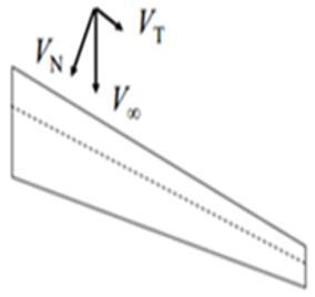
A sweepback of wing has a large influence on its aerodynamic characteristics at high speeds and very important foundation in a concept of aerodynamics. The swept wing shown in Figure 1 below has two components of velocity, one of them is vertical to the wing surface and the second is parallel to the wing surface. Then VN=V∞cosμ [11].
Figure 1. The wing sweep effect on the normal component of the air speed
Figure 2. The Mach cone angle in supersonic flow
If the leading edge of swept wing is outdoor Mach cone, the normal component of Mach number on the leading edge of foil is supersonic, therefore a large wave drag will produce. If the leading edge of swept wing is indoor Mach cone, the normal component of Mach number on the leading edge of foil is subsonic, thus the wave drag will reduce as shown in Figure 2.
Free stream Mach number and be resolved into three components as follow as:
Perpendicular to the aircraft wing, (M∞sinα)
In plane of the aircraft wing, but tangent to the leading edge; (M∞cosα sinμ) and
In plane of the aircraft wing, but perpendicular to the leading edge; (M∞cosα cosμ).
where, μ is Mach cone angle, and α is attack angle. The equivalent angle of attack and Mach number perpendicular to leading edge is represented and given by relations [12];
$M_{e q .}=M_{\infty} \sqrt{1-\sin ^{2} \mu \cos ^{2} \alpha}$ (1)
$\tan \left(\alpha_{e q .}\right)=\frac{\tan (\alpha)}{\cos \mu}$ (2)
And, the equivalent chord is shortened can be write ceq.=ccosμ and span is lengthened can be expressed by beq.=b/cosμ. Therefore, the equivalent lift coefficient and drag coefficient normal to leading edge can be written as;
$\left.\begin{array}{rl}C L_{e q .} & =\frac{C L}{1-\sin ^{2} \mu \cos ^{2} \alpha} \\ C D_{e q .} & =\frac{C D / \cos \mu}{1-\sin ^{2} \mu \cos ^{2} \alpha}\end{array}\right\}$ (3)
The whole wing lift to drag ration was determined and given by relations:
$\frac{L}{D}=\frac{\left(\frac{L}{D}\right)_{e q.}}{\cos \mu}$ (4)
The governing equations of the supersonic flow are the continuity equation, momentum equation and energy conservation equation. The complete system of these equations is presented below in a differential form. Knowing that the airflow is considered as a three dimensional, viscous and compressible flow [13, 14];
Continuity equation is:
$\frac{\partial \rho}{\partial t}+\nabla \cdot(\rho \bar{V})=0$ (5)
Momentum equation is:
$\nabla .(\rho . \bar{V} \bar{V})=-\nabla P+\nabla .(\bar{\tau})+\bar{F}$ (6)
Equation of energy conservation is:
$\frac{\partial(\rho E)}{\partial t}+\nabla .(\bar{v}(\rho E+P))=\nabla .\left[k_{e f f} \nabla T-\sum_{j} h_{j} \bar{J}_{j}+\left(\bar{\tau}_{e f f} . \bar{v}\right)\right]+S_{h}$ (7)
The airfoil model was created by using coordinate of NACA 2412. Then this model is fulfilled by making it solid surface. For the flow domain, a C-type is used as shown in Figure 3. The domain total horizontal length is 35 times the airfoil chord (20 times in front of the wing and 15 times behind the wing). Therefore, the air blockage inside the computational domain can be avoided using these dimensions. The asymmetry condition can be applied on the symmetry plane and thus a half of the flow domain is simulated for zero-yaw-angle fly conditions. The double-precision solver in Ansys 17.2 is used to make the CFD calculations. In this research, the 3D compressible Reynold–Averaged Navier –Stokes equations with the Sparlart–Allmaras turbulence model were employed. A quadratic scheme is used to estimate both diffusion and convective conditions. For coupling Pseud-transient pressure velocity, the pressure–coupled transient solver is used. No-slip barrier condition is used on the solid surface of wing. Pressure-distant arena conditions with Mach number (1.5) and overall pressure (0) are set to achieve the boundary condition of away-field unbounded flow at the external boundary of the computational flow domain [15-17]. To obtain reliable results, a grid independence test was done for all geometries and it was found that in most cases gives stable results for important aerodynamic parameters. The aerodynamic analysis is done for the fluid domain with the established boundary conditions. The dynamic grid was used in this work to mimic a situation with a boundary motion, such as a moveable wing body with a UDF (User Defined Function). A UDF is a function that may be dynamically attached to the Fluent solver and is written in the C programming language. In Fluent, UDFs may be implemented as collected or understood functions.
Figure 3. The 3D CFD mesh of a NACA 2412 wing
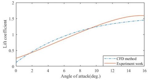
The computational simulation of the air flow about the NACA 2412 wing for validating the simulation method in Fluent software. The test is care out using supersonic wind tunnel with flow velocity up to Mach 1.8 directly to a Pc via USB and analysis there using the software supplied. The wind tunnel supplies an airstream flow from a one side to another under controlled test conditions to simulate the streamflow inside the working section of the wind tunnel in the laboratory. Figures 4 and 5 compare the lift and drag coefficients derived from CFD models at Reynolds number 3.2x10⁶ across a broad range of attack angle to experimental results [18, 19]. It is clear that the CFD modeling and simulation approach utilized in this study is appropriate for predicting flow around an airfoil wing. It also demonstrates that CFD simulations may provide a greater level of precision for geometry modification studies, such as swept wings, with the highest discrepancy between them falling within 12% at higher attack angles.
Figure 4. Variation of attack angle with Drag coefficient in different schemes
Figure 5. variation of attack angle with Lift coefficient in different schemes
The main concern for this study is to get the, flow visualization and determined the aerodynamic characteristics of the wing for supersonic speed. The sweep angle is varied of 0°, 20°, 40° and 60° deg, the wing has a chord length of 1m with NACA 2412 airfoils is extruding by 2.8 m. Because the wing has a symmetric geometry, so only a one half of the swept wing is needed to understand the physical phenomena of air flow at supersonic speeds, as well as flow visualization [20].
6.1 Pressure distribution
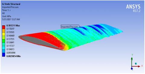
In the following section, the pressure distribution along the span of swept wing will be presented in contour below and show in Figure 6. The pressure distribution is zero at the tips, since there is a pressure balance between the bottom and the top of the wing. Therefore, no lift force will be generated in this case. The negative pressure is recorded when the flow around the wing accelerates and becomes positive as it approaches to the trailing edge. It can be seen that the areas of high pressure have moved downstream. The variation of pressure along wing span is of great importance in the wing design [21].
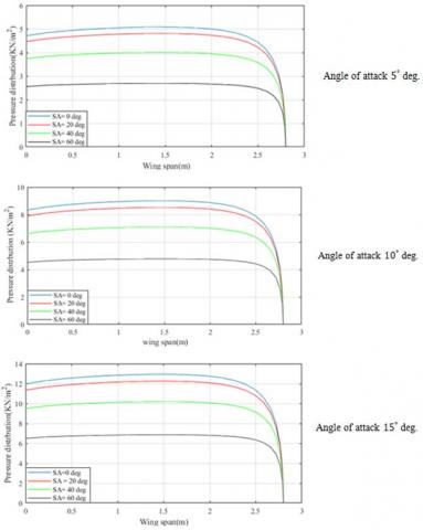
The sweep angle has a big influence on the magnitude of the load distribution, As the angle of sweep is increased, the velocity resultant towards the chord wise also increases. Therefore, the pressure drop happens according to the conservation law with respect to the increased sweep angle. The values of pressure calculated throughout the flow analysis at four sweep cases (0, 20, 40, 60) degree are presented in Figure 7.
Figure 6. Pressure contour over the wing at attack of 10º and sweep angle 20º
Figure 7. Pressure distribution over wing span for varies sweep angle and different AOA
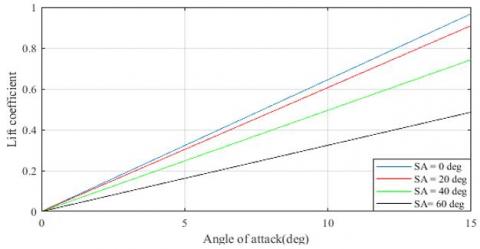
6.2 Lift coefficient
Figure 8. Lift coefficient against angle of attack at different sweep angle
An investigation of the influence of the sweep angle on the lift coefficient for various angles of attack was considered in Figure 8. At the 0º sweep angle, the wing has highest lift coefficient, and the trend of lift increase with an increase of attack angle, the highest value of the lift coefficient equals to 0.95 when the angle of attack equals 15º. At the sweep angle increase to 60º, the lift coefficient decreases and has the maximum value of 0.47. Due to the regular increase of the sweep angle which causes a decrease in the aspect ratio contributing to a drop in the wing span, the tangential velocity component growths with the sweep angle increasing. Moreover, the wing is affected by the downwash which causes an abrupt decrease in lift characterize. The results show that the wing with sweep angle of 60º can decrease the lift coefficient by the ratio of approximate 17% at the angle of attack 15º.
6.3 Drag coefficient
The results of attack angle against drag coefficient are presented in Figure 9. This is at different sweep angles. At a sweep angle of 0º, the higher drag coefficient is approximately 0.051, due to excessive skin friction in wing whereas; increasing the sweep angle about 60º the value of drag coefficient reduces to 0.031. The phenomena of shock waves formation on the swept wing surface, due to the air compressibility at high speeds, are less compared to the regular wings. Delaying shock wave formation has a positive effect on the overall drag coefficient. When the sweep angle is increased, the coefficient of drag force reduces by approximately 15.
Figure 9. Drag coefficient against angle of attack at different sweep angle
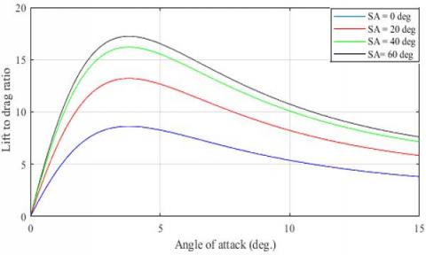
6.4 Lift-to-drag ratio
Figure 10. Typical variation of lift to drag ratio against the attack angle at different sweep angles
The results of the sweep angle effect on the ratio of lift/drag of the swept wing are shown in Figure 10. This is at different attack angles (0º to 15º). As shown in this figure that at zero-degree sweep angle, the maximum value of lift /drag ratio is about 8.5 (the blue curve). Whereas at sweep angle of 60º, the maximum life-to-drag ratio is near 17 (the black curve). This is at an angle of attack of about 3.5º for both cases. This because when the sweep angle is increased the freestream flow also increases, the flow is no longer vertical to the wings leading edge and will translate from the top to the bottom and vice versa on the surface of wing until it reaches the trailing edge of airfoil and leaves the wing surface. Generally, when the sweep angle is increased the lift to drag ratio increases by about 17%. In overall, the swept wing has good performance coefficient through the design envelope by optimizing the sweep to produce a high ratio of lift to drag.
The present research paper dealt with testing the effects of sweep on the wing aerodynamic characteristics (lift, drag, and performance) at different angles of attack. The 3D wing model analyzed and presented in this paper of NACA 2412 profile. The numerical computations were done in Fluent software to examine the influences of variable parameters. The dynamic grid method was used for recreating the mesh, after the validation of the 3D swept wing to predict the aerodynamic characteristics on the wing through variation of sweep angle and over a broad range of angles of attack. It was found that the wing sweeps beneficial in decreases in wave drag for supersonic flows, enhanced L/D ratio significantly higher by 10%. The optimum wing sweep angle can only be determined by studying a multidisciplinary design including wing structure, control stability and aircraft flight.
[1] Asselin, M. (2019). An Introduction to Aircraft Performance. Royal Military College of Canada.
[2] Abdelghany, E.S., Khalil, E.E., Abdellatif, O.E., ElHarriri, G. (2016). Winglet cant and sweep angles effect on aircraft wing performance. Proceedings of the 17th Int. AMME Conference, pp. 258-274.
[3] Sadraey, M.H. (2017). Aircraft Performance: An Engineering Approach. CRC Press. https://doi.org/10.1201/9781315366913
[4] Al-Obaidi, A.S.M., Kui, E.T.N. (2014). The effect of wing geometry on lift at supersonic speeds. Journal of Engineering Science and Technology, 8: 16-27.
[5] Manshadi, M.D., Aghajanian, S. (2018). Computational aerodynamic optimization of wing-design concept at supersonic conditions by means of the response surface method. Journal of the Brazilian Society of Mechanical Sciences and Engineering, 40(5): 254. https://doi.org/10.1007/s40430-018-1150-4
[6] Güzelbey, İ.H., Eraslan, Y., Doğru, M.H. (2019). Effects of taper ratio on aircraft wing aerodynamic parameters: A comperative study. European Mechanical Science, 3(1): 18-23. https://doi.org/10.26701/ems.487516
[7] Balaji, R., Dash, P.K. (2017). Swept wing aerodynamic at transonic speeds and at different turbulence levels. International Journal of Current Research, 9(6): 52513-52521.
[8] Secanell, M., Suleman, A., Gamboa, P. (2006). Design of a morphing airfoil using aerodynamic shape optimization. AIAA Journal, 44(7): 1550-1562. https://doi.org/10.2514/1.18109
[9] Talay, T.A. (2012). Introduction to the Aerodynamics of Flight. NASA Langley Research Center Hampton, VA, United States.
[10] Li, P., Sobieczky, H., Seebass, R. (1995). A design method for supersonic transport wings. In 13th Applied Aerodynamics Conference. https://doi.org/10.2514/6.1995-1819
[11] Ejeh, C.J., Akhabue, G.P., Boah, E.A., Tandoh, K.K. (2019). Evaluating the influence of unsteady air density to the aerodynamic performance of a fixed wing aircraft at different angle of attack using computational fluid dynamics. Results in Engineering, 4: 100037. https://doi.org/10.1016/j.rineng.2019.100037
[12] Dung, H.T.K., Khanh, N.P. (2020). Research on aeroelasticity phenomenon in aeronautical engineering. In Aerodynamics. IntechOpen.
[13] Samal, S.K., Shah, D.A., Bharath, M., Sahoo, A. (2013). Computational prediction of tipvortex of a swept wing. Int. J. Innovat. Res. Sci. Eng. Technol, 2.
[14] Darwish, M., Moukalled, F. (2021). The Finite Volume Method in Computational Fluid Dynamics: An Advanced Introduction with OpenFOAM® and Matlab. Springer. https://doi.org/10.1007/978-3-319-16874-6
[15] Ünay, E. (2015). Load analysis of an aircraft using simplified aerodynamic and structural models. Master's Thesis, Middle East Technical University.
[16] Asselin, M. (2012). An Introduction to Aircraft Performance. Royal Military College of Canada. https://doi.org/10.2514/4.861529
[17] Al-Zughaibi, A., Hussein, E.Q., Rashid, F.L. (2021). Numerical investigations of fluid structural interaction for aircraft wing flap structure using CFD technique. Journal of Mechanical Engineering Research and Developments, 44(3): 138-150.
[18] Harper, C.W., Maki, R.L. (1964). A Review of the Stall Characteristics of Swept Wings. National Aeronautics Space Administration, Washington, D.C.
[19] Takeuchi, K., Matsushima, K., Kanazaki, M., Kusunose, K. (2015). CFD analysis on sweep angles of the leading and trailing edges of a wing in a supersonic flow. Transactions of the JSME (in Japanese), 81(827): 15-00037. https://doi.org/10.1299/transjsme.15-00037
[20] Hussein, E.Q., Azziz, H.N., Rashid, F.L. (2021) Aerodynamic study of slotted flap for NACA 24012 airfoil by dynamic mesh techniques and visualization flow. Journal of Thermal Engineering, 7(2): 230-239. https://doi.org/10.18186/thermal.871989
[21] Hussein, E.Q., Rashid, F.L., Azziz, H.N. (2019). Aerodynamic heating distribution for temperature prediction of fast flying body nose using CFD. Journal of Advanced Research in Fluid Mechanics and Thermal Sciences, 64(2): 183-195.