Muhammad Asmail Eleiwi | Farhan Lafta Rashid* | Abbas Fadhil Khalaf | Sohaib Abdulrahman Tuama
© 2022 IIETA. This article is published by IIETA and is licensed under the CC BY 4.0 license (http://creativecommons.org/licenses/by/4.0/).
OPEN ACCESS
Conjugate heat transfer (CHT) happens often in engineering environments, involving convection as well as conduction in a fluid flow and a rigid body in contact with each other. Although the analytical solutions for the problems of the individual convection and conduction are surprisingly simple, solving the combined conjugate heat transfer problem is much more difficult. The CHT of a fluid (air) flowing past an unbounded sphere is the subject of this research. ANSYS Fluent V.16.0 is employed to solve the governing equations using a finite volume system, assuming axisymmetric, no normal convection, and steady physical properties. Heat is generated at a consistent and uniform rate by the sphere. The results demonstrated that as the air temperature rises, so does the temperature distribution. The temperature distribution will be reduced as the rate of air flow is raised. Also, the distribution of temperature will rise as the sphere heat flux increases. The flow rate distribution will increase as the air flow rate rises. The distribution of pressure will rise as the rate of air flow raises.
conjugate heat transfer, computational fluid dynamics, convection, finite volume method, sphere, thermal conduction
In many non-Newtonian fluid flows, heat transfer is an important method. While, no flow is rigorously isothermal from a theoretical perspective, the isothermal supposition may be used with marginal error within many cases of applied importance. Processes of heat transfer frequently necessitate study the phases of fluid and solid, which interfere with one another, unless simplifications are made. There is a movement in the fluid in certain problems of CHT, and heat being transferred between various phases. When the temperature distribution within the sphere is non-trivial, the non-isothermal flow past a sphere being a problem of the conjugate heat transfer which arises from the energy expression solution within a solid domain. And this can happen if a sphere generates heat in its inside and being submerged in a cold air stream, as in the comprehensive image of the issue discussed in this paper [1-3].
In many engineering systems, the CHT that comprises the joined convection and conduction is important. Solving the fields of temperature with a fluid that moves in contact with a rigid body, where the thermal convection inside the field of fluid happens in tandem with the conduction inside the field of solid, has occupied a significant portion of previous studies. Whereas, the conduction influence in the solid body being significant in the area of the thermally forming fluid, also it's significant in the state of the production of internal heat in the solid which is convicted via the moving fluid. As a result, developing analytical solutions for conjugate problems, including the conduction and convection of a flow of fluid in a solid that is in contact with the flow of fluid is important. Problems of the internal and external flow being of concern [4].
The solutions of the problems of the only conduction or convection are reasonably simple to deduce. For complex boundary conditions, like fixed heat flux or fixed temperature, famous solutions exist. Theoretical explanations for a wide range of conductivity issues are also available. The theoretical temperature spreading derivation in the problems of conjugate, on the other hand, is even more difficult. Graetz and Jacob [5, 6] was the first to solve a basic difficulty underlying many CHTs problems by deriving an empirical formula for the temperature in a fluid that flows throughout a channel with a fixed temperature boundary condition, supposing that the flow is evolved hydrodynamically and thermally. This solution was given analytical expressions for Eigenvalues and Eigen functions, and it was utilized for deriving the solution for a further overall problem of unceasingly or separately changing the wall temperature employing linear superimposition. The solution of boundary layer for the flow of fluid above a plate was investigated for the thermal boundary layer non-similarity caused via the field of velocity and the streamwise temperature variation. The case of axially varying or continuous heat flux of the wall was also investigated. Although the axial conduction within fluids being generally ignored, some research papers have taken into account this phenomenon, which is important for some technical applications [7].
Many numerical analyses of the conjugate effect in circular and noncircular ducts have been conducted. The finite heated duration effect upon the features of heat transfer of a fully formed laminar flow throughout circular ducts having walls with a high thickness was investigated by Campo and Schuler [8]. Four dimensionless groups ruled this type of conjugate problem: The Peclet sum, the ratio of the solid-fluid thermal conductivity, the heated area length, and the solid wall diameters ratio. The 2D wall provides a heat transfer channel into the flow of fluid, regulating the interested variables, like the fluid bulk temperature and the two exterior beside the internal surface temperatures of the wall of solid, according to their numerical effects. Based on the analysis of a number of standard events, it was determined that both surface temperatures and bulk temperature distributions displayed critical differences in the axial direction, with the distribution of bulk temperature showing lesser and more incremental variations. Aydin et al. [9] utilized the finite volume technique for examining the laminar CHT inside a tube exposed to an axially non-uniform heat flux at the outside surface of tube. For a variety of matching variables, the outcomes of the diameter ratio and thermal conductivity ratio, temperature and the distribution of heat flux at the interface, are calculated. The steady-state study of the CHT for the thermal entrance area for formed laminar flow forced convection inside a circular duct was proposed by Luna et al. [10]. At the duct's exterior surface, a uniform heat flux was applied. The integral boundary layer estimate was employed for solving the equation of energy analytically, ignoring the heat generation due to the viscous dissipation as well as the axial heat conduction in fluid. Al-Zaharnah et al. [11, 12] published an overview of the thermal stresses in a fully formed laminar flow. A control volume method was utilized for solving numerically the governing energy equation via implementing a homogenous heat flux to the outer surface of duct. To solve the CHT problems, Barozzi and Pagliarini [13] suggested a general technique incorporating the superposition opinion with a FEM. Effect of the conduction of wall upon the heat transfer of a fully formed laminar flow throughout a circular duct having uniform heat flux being considered in this process. Elmarghany et al. [14] used a compact thermal model to achieve a more general straightforward expression for any heat flux density and temperature profiles, which has many benefits over the conventional solution based on the heat transfer coefficient (i.e. any space distribution, not just uniform). As a result, a steady-state compact thermal model is developed and applied to a CHT in a circular duct. Throughout the length of the duct, the flow is called laminar and hydrodynamically completely formed. In each of the examined situations, the temperature distributions of the moving fluid within the duct at various parts have been presented. For the conjugate heat transfer, the portable thermal model was also used to analyze the temperature distribution and heat flux at the interface.
Pimenta and Alves [15] studied the CHT of a streamlined (PTT) fluid that flows preceding a boundless sphere in the Stokes system (Re is equal to 0.01). The problem was solved numerically with the finite-volume technique supposing the axisymmetry, nonexistence of the natural convection and fixed physical characteristics. This sphere creates heat at a rate which is fixed as well as homogenous; also the analysis was carried out within a Deborah range (0≤De≤100), a Prandtl range (100≤Pr≤105), and a Brinkman numbers range (0≤Br≤100), in the existence or nonexistence of the thermal resistance of contact at the interface (solid-fluid) and for various conductivity ratios (0.1≤κ≤10). The drag coefficient showed a monotonic reduction with (De), while the regularized stresses upon the surface of sphere as well as in the wake initially augmented and after that reduced with (De). A negative wake being noticed for the (2) examined ratios of solvent viscosity (β is equal to 0.1 and 0.5), which is highly concentrated for the highly elastic fluid.
The aim of this research is to investigate a continuous and uniform volumetric heat source at the interior of the sphere that heats the fluid in contact. Conduction and induced convection are used to transfer the heat to the fluid; the natural convection being ignored. The fluid and the sphere are also part of the structure under investigation. The research is performed under steady-state conditions. The two key goals of the present investigation are firstly for clarifying the problem mechanics beneath the investigation and, secondly, for including a benchmark evidence for a conjugate heat transfer problem comprising a visco-elastic fluid, which is according to the knowledge of authors, being the principal in literature.
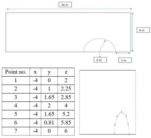
Consider the boundless flow of a visco-elastic fluid through a sphere that generates the heat in its interior at a rate which is steady as well as homogenous. The geometry of problem is diagrammatically represented in Figure 1. This sphere has a radius of (R=D/2=2 m) and is submerged in a rectangular field with dimensions (16 m × 6 m) around the sphere beginning by 2 m from the right hand side. The computational space is rendered broadly enough that the solution is unaffected by the surrounding boundaries. The fluid domain's outer borders were reserved rectangular for making easier meshing and for achieving cells with low non-orthogonality in the fluid domain. Boundary criteria were applied as follows:
Figure 1. Dimensions and Coordinates of the case study
3.1 Fluid region
3.1.1 The conservation of mass and the balance of momentum
The conservation of mass (Eq. (1)) and the balance of momentum (Eq. (2)) can be written [16-18]:
$\nabla . u$ (1)
$\rho_{f} \cdot u \cdot \nabla u=-\nabla_{p}+\eta_{s} \nabla^{2} u+\nabla \cdot \tau$ (2)
where, u: The vector of velocity; p: Pressure; τ: Polymeric extra-stresses tensor; ρf: Fluid density; ηs: Solvent viscosity.
3.1.2 The constitutive equation
Many constitutive expressions can be accessible for modeling the viscoelastic fluids rheology [19-21].
$\exp \left(\frac{\varepsilon \lambda}{\eta_{p}} \operatorname{tr}(\tau)\right) \tau+\lambda \tau^{\nabla}=\eta_{p}\left(\nabla u+\nabla u^{T}\right)$ (3)
where, ε is the extensibility factor, λ is the relaxation period of fluid, and τ∇ is the upper-convected period derivative of τ.
3.1.3 Energy equation
The conservation of energy, written here as a function of the factor of temperature, and can be expressed (ignoring the transfer of heat via the radiation) [22-25] as:
$\rho_{f} \cdot C_{p, f}(u \cdot \nabla T)=\nabla \cdot\left(k_{f} \nabla T\right)+\tau^{\prime}: \nabla u$ (4)
where, T: The temperature; kf: The fluid thermal conductivity; Cp,f: The fluid specific heat capacity.
It's worth observing that the term of viscous dissipation (τ':∇u) corresponds to the state of the pure entropy elasticity of the highly overall term of viscous dissipation.
3.2 The solid region
3.2.1 Equation of energy
In a solid region, that means within the sphere, merely the equation of energy being solved:
$\nabla \cdot\left(k_{s} \nabla T\right)+\Phi=0$ (5)
where, (ks) represents the solid thermal conductivity, and Φ represents the volumetric source of energy.
3.2.2 The interface (solid-fluid)
The equation of energy, which being solved upon the two sides of interface, needs a careful attention at the sphere's surface (Eqns. (4) and (5)). Because of the energy conservation law, the heat flux that crosses the surface of sphere should be equivalent upon the two sides. Because the heat is transmitted by conduction at the sphere's surface, the preceding state being equal to [26-28]:
$\left(k_{s} \nabla T\right)_{s, i} \cdot n_{s}=\left(-k_{f} \nabla T\right)_{f, i} \cdot n_{f}$ (6)
In such overall state, the temperature also complies with the state:
$\left(-k_{s} \nabla T\right)_{s, i} \cdot n_{s}=h_{r e s}\left(T_{s, i}-T_{f, i}\right)$ (7)
where, Tf,i and Ts,i: The temperature at the interface upon the sides of fluid and solid, correspondingly; hres: The coefficient of heat transfer describing the resistance to contact.
3.3 Generation of mesh
A volume grid within the field of flow requires to be generated, and the whole boundaries surfaces want to be discretized prior to the governing equations can be solved numerically. That's conducted by a method recognized as a meshing. The meshing comprises (458300) node points that are from the volumes of cell or occasionally also named elements (440326). Figure 2 shows the mesh generation for the case.
Figure 2. Mesh generation
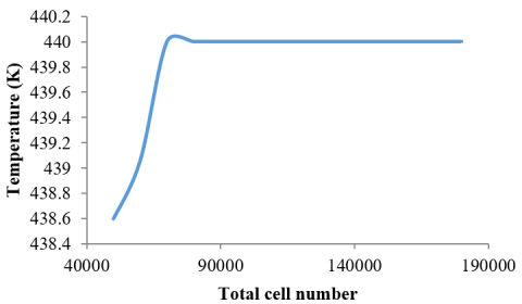
3.4 Study the independency of grid
The effect of the size of mesh upon the outcomes sensitivity has to be investigated for the initial stage of achieving a simulation of the CFD. For further precise method, further nodes being wanted, and utilizing more nodes shall escalate the required computational period of computation and memory of computer [29-31]. For determining the appropriate nodes no., it can be achieved via raising the no. of nodes till the mesh becomes fine. The change of temperature with the no. of grid cell for heat flux of (100 W/m2), temperature (293 K) of inlet air, and the rate of air flow (0.01 m3/s) is presented in Figure 3. It was depicted that the increment in the no. of cell raises the temperature till attaining to an almost fixed value.
Figure 3. Study the independency of grid for the heat flux of 100 W/m2, temperature (293 K) of inlet air, and the rate of air flow (0.01 m3/s)
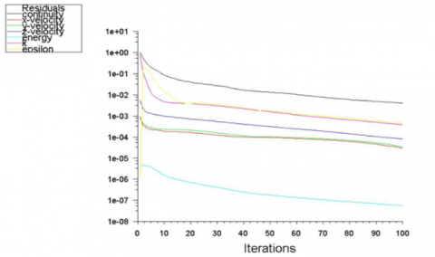
The numerical results of CHT between spherical solid body and fluid (air) are presented. Solving the governing equations by the scheme of finite volume founded upon ANSYS FLUENT V.16.0. The geometry of the assumed case was created using AUTO CAD 2015 and then imported to a FLUENT code. A solution is converged if the whole conservation equations (continuity, energy, x-velocity, y-velocity, z-velocity, and k-epsilon) being complied with the whole points to an identified tolerance [32-34]. Figure 4 shows the output of the convergence.
Figure 4. Convergence to solve discrete conservation equations
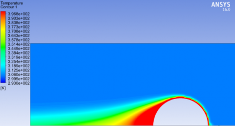
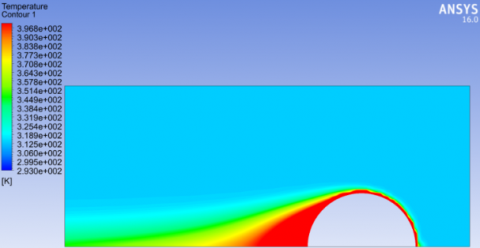
Figures 5, 6, and 7 evince the temperature distribution contour of the air flow case from the right to left with 0.01 m3/s, heat flux of 100 W/m2, and temperature of 293, 303, and 313 K, respectively. The sphere created wakes developed into vortices at the downstream. This led to raise the transfer of heat from the body of sphere to the coolant air, that means increased the temperature of coolant air [35-37]. Different temperature contours were seen depending on the coolant air temperature.
Figure 8 manifests the temperature distribution along the seventh points around the sphere. Also, it shows that the temperature at the points (1-4) increased, respectively, then decreased at point 5, then increased at points 6, and again decreased at point 7. This is because the stagnation point will be at point 1 (i.e. the velocity of air will be zero), thus there is a minimum heat transfer occurred at point 1. At points 2, 3, and 4, the air flow will raise, respectively and thus increases the heat transfer. At point 5, the air flow velocity seems to be maximum (as shown in Figure 9), thus a maximum heat transfer will occur at this point which leads to minimize the temperature. The scene will be repeated at the points 6 and 7.
Figure 5. Contour of temperature distribution for air temperature of 293 K and heat flux of 100 W/m2
Figure 6. Contour of temperature distribution for air temperature of 303 K and heat flux of 100 W/m2
Figure 7. Contour of temperature distribution for air temperature of 313 K and heat flux of 100 W/m2
Figure 8. Temperature distribution along the spherical body for 100 W/m2 and the inlet air temperature of 293 K, at air flow rate 0.01 m3/s
Figure 9. Flow rate distribution along the spherical body for 100 W/m2 and the inlet air temperature of 293 K, at air flow rate 0.01 m3/s
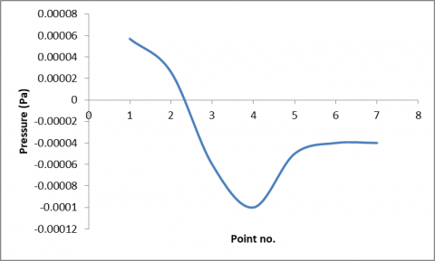
Figure 10. Pressure distribution along the spherical body for 100 W/m2 and inlet air temperature of 293 K, at air flow rate 0.01 m3/s
Figure 10 reveals the pressure distribution across the seventh point along the circumstance of sphere. It shows that the pressure distribution be symmetric along the two halves of sphere, the maximum value at point 1, and minimum at point 4 (vacuum). At point 7, the value of pressure is equal to that at point 1 but in opposite sign.
Figure 11 elucidates the temperature distribution along the seventh points around the sphere with different air inlet temperatures. It shows that the increase in air temperature will increase the temperature distribution.
Figure 11. Temperature distribution along the spherical body for 100 W/m2 and different inlet air temperatures, at air flow rate 0.01 m3/s
Figure 12 demonstrates the temperature distribution along the seventh points around the sphere with different air flow rates. Also, it depicts that the increment in the rate of air flow will decrease the distribution of temperature [38-42].
Figure 12. Temperature distribution along the spherical body for 100 W/m2 and the inlet temperature of air stream (293 K) with different air flow rates
Figure 13 illustrates the temperature distribution along the seventh points around the sphere with different sphere heat fluxes. Also, it reveals that the increase in the sphere heat flux will increase the temperature distribution.
Figure 13. Temperature distribution along the spherical body and the inlet temperature of air stream (293 K) with different heat fluxes (100 and 200 W/m2)
Figure 14 views the air flow rate along the seventh points around the sphere with different air flow velocities. Also, it illustrates that the increase in the air flow rate will increase the flow rate distribution.
Figure 15 appears the pressure distribution along the seventh points around the sphere with different air flow rates. Also, it presents that the increase in the air flow rate will increases the distribution of pressure.
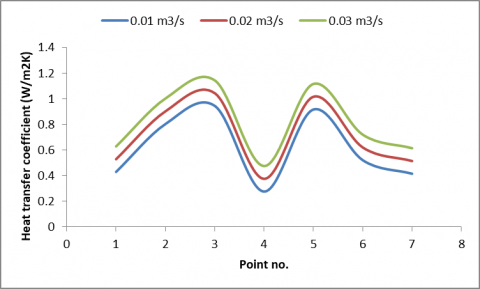
Figure 16 portrays the heat transfer coefficient along the seventh points around the sphere with different air flow rate. Also, it displays that the increment in the rate of air flow will raise the coefficient of heat transfer. The maximum value of heat transfer coefficient occurs at the points (3, 5), while the minimum value took place at the point (4), because the highest value of air flow rate is at the points (3, 5), whereas the minimum air flow rate is at the point (4).
Figure 14. Flow rate (flow velocity) along the spherical body and the inlet temperature of air stream (293 K) with different air flow rates
Figure 15. Pressure distribution along the spherical body and the inlet temperature of air stream (293 K) with different air flow rates
Figure 16. Heat transfer coefficient along the spherical body and the inlet temperature of air stream (293 K) with different air flow rates
This research looked into the heat transfer as well as the boundless flow of a streamlined flow of air fluid passing through a sphere. The sphere's interior produces heat at a consistent and uniform scale. Advanced simulation of the problems of the convective CHT is presently widely utilized in a variety of fields. This technique, which began with basic examples in the 1965–1970s, is now used to construct models of a wide range of system function in addition to the technology systems, from easier processes to complicated multistage, non-linear procedures. The subsequent conclusions are drawn:
(1) The increase in air temperature will raise the temperature distribution.
(2) The rise in the rate of air flow will decrease the temperature distribution.
(3) The increase in the sphere heat flux will increase the temperature distribution.
(4) The rise in the rate of air flow will raise the flow rate distribution.
(5) The rise in the rate of air flow will increase the pressure distribution.
Authors acknowledge the infrastructure of Tikrit University, and Kerbala University in terms of literature databases and software.
[1] Dey, S., Ali, S.Z., Padhi, E. (2019). Terminal fall velocity: The legacy of Stokes from the perspective of fluvial hydraulics. Proceedings of the Royal Society A, 475(2228): 20190277. https://doi.org/10.1098/rspa.2019.0277
[2] Bhatnagar, R.K. (1970). On heat transfer in a viscoelastic fluid flowing around a steadily rotating and thermally insulated sphere. Rheologica Acta, 9(3): 419-423. https://doi.org/10.1007/BF01975410
[3] Dhole, S.D., Chhabra, R.P., Eswaran, V. (2006). A numerical study on the forced convection heat transfer from an isothermal and isoflux sphere in the steady symmetric flow regime. International Journal of Heat and Mass Transfer, 49(5-6): 984-994. https://doi.org/10.1016/j.ijheatmasstransfer.2005.09.010
[4] Shah, K., Jain, A. (2015). An iterative, analytical method for solving conjugate heat transfer problems. International Journal of Heat and Mass Transfer, 90: 1232-1240. http://dx.doi.org/10.1016/j.ijheatmasstransfer.2015.07.056
[5] Graetz, L. (1883). Uber Die Warmeleitungsfahigheit Von Flussingkeiten—Part 1. Annalen der Physik und Chemie, 18: 79-94.
[6] Jacob, M. (1949). Heat Transfer. First ed., John Wiley & Sons, New York.
[7] Yin, X., Bau, H.H. (1996). The conjugate Graetz problem with axial conduction. Transactions-American Society of Mechanical Engineers Journal of Heat Transfer, 118: 482-484.
[8] Campo, A., Schuler, C. (1988). Heat transfer in laminar flow through circular tubes accounting for two-dimensional wall conduction. International Journal of Heat and Mass Transfer, 31(11): 2251-2259. https://doi.org/10.1016/0017-9310(88)90157-3
[9] Aydin, O., Avci, M., Bali, T., Arıcı, M.E. (2014). Conjugate heat transfer in a duct with an axially varying heat flux. International Journal of Heat and Mass Transfer, 76: 385-392. http://dx.doi.org/10.1016/j.ijheatmasstransfer.2014.04.062
[10] Luna, N., Méndez, F., Trevino, C. (2002). Conjugated heat transfer in circular ducts with a power-law laminar convection fluid flow. International Journal of Heat and Mass Transfer, 45(3): 655-666. http://dx.doi.org/10.1016/S0017-9310(01)00147-8
[11] Al-Zaharnah, I.T., Hashmi, M.S., Yilbas, B. (2001). Thermal stresses in thick-walled pipes subjected to fully developed laminar flow. Journal of Materials Processing Technology, 118(1-3): 50-57. http://dx.doi.org/10.1016/S0924-0136(01)00862-7
[12] Al-Zaharnah, I.T., Yilbas, B.S., Hashmi, M.S.J. (2000). Conjugate heat transfer in fully developed laminar pipe flow and thermally induced stresses. Computer Methods in Applied Mechanics and Engineering, 190(8-10): 1091-1104. http://dx.doi.org/10.1016/S0045-7825(99)00467-3
[13] Barozzi, G.S., Pagliarini, G. (1985). A method to solve conjugate heat transfer problems: The case of fully developed laminar flow in a pipe. Journal of Heat Transfer, 107(1): 77-83. http://dx.doi.org/10.1115/1.3247406
[14] Elmarghany, M.R., Mansour, M.H., Sultan, A.A., Sabry, M.N. (2016). Modeling of conjugate heat transfer. Mansoura Engineering Journal, 41: 16-23. http://dx.doi.org /10.21608/bfemu.2020.99354
[15] Pimenta, F., Alves, M.A. (2021). Conjugate heat transfer in the unbounded flow of a viscoelastic fluid past a sphere. International Journal of Heat and Fluid Flow, 89: 108784. http://dx.doi.org/10.1016/j.ijheatfluidflow.2021.108784
[16] Eleiwi, M.A., Zainal, O.A., Tahseen, T.A., Mustafa, A.W. (2021). Effect of front air attack angles on heat transfer coefficient of the cross‐flow of four flat tube. Heat Transfer, 50(1): 638-654. http://dx.doi.org/10.1002/htj.21897
[17] Eleiwi, M.A., Tahseen, T.A., Ghareeb, A.H. (2020). Intelligent control based estimation of heat transfer coefficient from four flat tubes with different attack air angles. Journal of Advanced Research in Fluid Mechanics and Thermal Sciences, 72(2): 65-78. https://doi.org/10.37934/arfmts.72.2.6578
[18] Tahseen, T.A., Eleiwi, M.A., Hameed, A.F. (2020). Numerical study of fluid flow and heat transfer in a backward facing step with three adiabatic circular cylinder. Journal of Advanced Research in Fluid Mechanics and Thermal Sciences, 72(1): 80-93. https://doi.org/10.37934/arfmts.72.1.8093
[19] Mahood, H.B., Rasheed, F.L., Abbas, A.K. (2011). Analytical and numerical investigation of transient gas blow down. Modern Applied Science, 5(5): 64. https://doi.org/10.5539/mas.v5n5p64
[20] Altaie, A., Hasan, M.R., Rashid, F.L. (2014). Numerical heat transfer and turbulent flow in a circular tube fitted with opened rings having square cross section. Journal of Basic and Applied Scientific Research, 4(11): 28-36.
[21] Rashid, F.L., Altaie, A., Hasan, M.R. (2014). Numerical investigation of heat transfer enhancement in a circular tube using ribs of separated ports assembly. European Scientific Journal, 10(10).
[22] Altaie, A., Hasan, M.R., Rashid, F.L. (2015). Numerical investigation of heat transfer enhancement in a circular tube with rectangular opened rings. Bulletin of Electrical Engineering and Informatics, 4(1): 18-25. https://doi.org/10.11591/eei.v4i1.331
[23] Altaie, A., Hasan, M.R., Rashid, F.L. (2015). Heat transfer enhancement in a circular tube using ribs with middle arm. Elixir International Journal, 5(2).
[24] Altaie, A., Hasan, M.R., Rashid, F.L. (2015). Numerical investigation in a circular tube to enhance turbulent heat transfer using opened rings-triangular cross section. Journal of Babylon University/Engineering Sciences.
[25] Rashid, F.L., Hashim, A. (2020). Recent review on nanofluid/nanocomposites for solar energy storage. International Journal of Scientific Research and Engineering Development, 3(4): 780-789.
[26] Al-Jibory, M.W., Rashid, F.L., Hussein, H.Q. (2018). Heat transfer augmentation in gas turbine blade rectangular passages using circular ribs with fins. Journal of University of Babylon for Engineering Sciences, 26(1): 247-258.
[27] Al-Jibory, M.W., Rashid, F.L., Talib, S.M. (2018). Numerical investigation of heat transfer enhancement in ribbed elliptical passage. Journal of Engineering and Applied Sciences, 13(17): 7223-7234. https://doi.org/10.3923/jeasci.2018.7223.7234
[28] Rashid, F.L., Azziz, H.N., Hussein, E.Q. (2018). Heat transfer enhancement in air cooled gas turbine blade using. Journal of Petroleum Research and Studies, 8(3): 52-69. https://doi.org/10.52716/jprs.v8i3.230
[29] Aljibory, M.W., Rashid, F.L., Alais, S.M.A. (2018). An Experimental and numerical investigation of heat transfer enhancement using annular ribs in a tube. In IOP Conference Series: Materials Science and Engineering, 433(1): 012057. https://doi.org/10.1088/1757-899X/433/1/012057/meta
[30] Rashid, F.L., Al-Jibory, M.W., Talib, S.M. (2018). Numerical investigation of heat transfer augmentation in elliptical passage with different rib geometries and aspect ratios. International Journal of Mechanical Engineering and Technology, 9(13): 1390-1409.
[31] Al-Jibory, M.W., Rashid, F.L., Talib, S. (2018). An experimental investigation of heat transfer enhancement in elliptical passage fitted with different rib geometries. International Journal of Mechanical Engineering and Technology, 9(13): 1033-1048.
[32] Rashid, F.L., Hussein, H.Q., Bded, A.S. (2019). Numerical simulation of fluid flow and heat transfer in wellbore. Journal of Advanced Research in Fluid Mechanics and Thermal Sciences, 60(1): 60-70.
[33] Hussein, E.Q., Rashid, F.L., Azziz, H.N. (2019). Aerodynamic heating distribution for temperature prediction of fast flying body nose using CFD. Journal of Advanced Research in Fluid Mechanics and Thermal Sciences, 64(2): 183-195.
[34] Al-Jibory, M.W., Rashid, F.L., Hussein, H.Q. (2018). Heat transfer augmentation in gas turbine blade rectangular passages using circular ribs with fins. Journal of University of Babylon for Engineering Sciences, 26(1): 247-258.
[35] Al-Jibory, M.W., Rashid, F.L., Talib, S.M. (2020). Review on cooling enhancement of different shape gas turbine ribbed blade with thermal barrier coating. International Journal of Scientific Research and Engineering Development, 3(1): 313-329.
[36] Al-Jibory, M.W., Rashid, F.L., Hussein, H.Q. (2020). Review of heat transfer enhancement in air-cooled turbine blades. International Journal of Scientific & Technology Research, 9(04): 3123-3130.
[37] Hussein, H.Q., Al-Jibory, M.W., Rashid, F.L. (2020). Heat transfer enhancement of gas turbine blades using coated ribs with nanocomposite materials. Journal of Mechanical Engineering Research and Developments, 43(6): 09-22.
[38] Hussein, E.Q., Azziz, H.N., Rashid, F.L. (2021). Aerodynamic study of slotted flap for NACA 24012 airfoil by dynamic mesh techniques and visualization flow. Journal of Thermal Engineering, 7(2): 230-239. https://doi.org/10.18186/thermal.871989
[39] Al-Zughaibi, A., Hussein, E.Q., Rashid, F.L. (2021). Numerical investigations of fluid structural interaction for aircraft wing flap structure using CFD technique. Journal of Mechanical Engineering Research and Developments, 44(3): 138-150.
[40] Redha, Z.A.A., Rashid, F.L. (2021). Heat transfer enhancement in subchannel geometry of pressurized water reactor using water-based yttrium oxide nanofluid. International Journal of Heat and Technology, 39(3): 979-986. http://dx.doi.org//10.18280/ijht.390335
[41] Rashid, F.L., Redha, Z.A.A., mohammed, A.A. (2021). Thermal analysis on the fuel rod assemblies with triangular and square array using new nanofluid. Journal of Engineering Science and Technology, 16(5): 3801-3821.
[42] Abdulkarim, A.H., Eleiwi, M.A., Tahseen, T.A., Canli, E. (2021). Numerical forced convection heat transfer of nanofluids over back facing step and through heated circular grooves. Mathematical Modelling of Engineering Problems, 8(4): 597. http://dx.doi.org//10.18280/mmep.080413