Ameer Mohsin Hashim* | Ammar Yasier Ali
© 2022 IIETA. This article is published by IIETA and is licensed under the CC BY 4.0 license (http://creativecommons.org/licenses/by/4.0/).
OPEN ACCESS
This study is devoted to test the structural response of reinforced concrete horizontally curved box beams in presence of vertical and transverse opening restored by CFRP Laminates or Reactive Powder Concrete (RPC) technique and compared to that having opening but without restoring. Six horizontally circular curved box beams were casted and tested in this experimental work, three specimens with opening in vertical direction and the other three specimens including opening in transverse direction. Accordingly, each direction has three types of beams, first one including opening without restoring and used as a reference specimen, second one with opening restored by CFRP Laminates technique and third one with opening restored by Reactive Powder Concrete (RPC) technique. The test program includes the main variables; direction of opening. The beams were tested as a two-span continuous beam, each span represents a quarter circle, under the effect of two concentrated loads each load positioned at top face of midspan of the beam. The findings of the experiments showed that the use of Reactive Powder Concrete (RPC) and CFRP Laminates and techniques around opening notably increased the ultimate load capacity of specimens (CB2.V60.S1, CB3.V60.S2, CB5.T60.S1 and CB6.T60.S2) by about (18.5% and 15.3%,135% and 38.3%) respectively, when compared with specimens without restoring. Service mid-span deflection response not give clear effect, while service mid-span twisting was improved by about (55.28%, 13%, 10.73% and 2.37%) for all restored specimens (CB2.V60.S1, CB3.V60.S2, CB5.T60.S1 and CB6.T60.S2) respectively. Genially, significant increase in stiffness can be observed for restored specimens as a comparison with those without restoring.
circular box beam, opening, deformation response, ductility, stiffness, CFRP laminates, Reactive Powder Concrete (RPC)
Box girders (hollow beams), acquire wide acceptance in civil engineering Due to their structural efficiency, better stability, serviceability, construction economy, and aesthetics, freeway and bridge systems [1]. These hollow sections are used to provide pass-through property for electrical and mechanical facilities, as well as reduce story height and material and construction costs. Numerous studies including experimental, theoretical and numerical were carried out on the behavior of box girders essentially concentrated on straight, single or multi-cell Box girders, developing of numerical methods for a comparison of experimental and computational study to evaluate the nonlinear response, collapse modes, and ultimate failure loads of multi-cell RC (reinforced concrete) box girder bridges under gradually rising static loads [2-6].
Box girders (hollow beams) that carry a number of cables and tubes for many services water supply, for example sewerage, air conditioning, electricity, telephone, and computer network, sometimes need to include an opening in the horizontal walls and vertical walls to reach and maintain those cables and pipes. Structural behavior for reinforced concrete horizontally curved box beams with an opening in transverse or vertical direction have not been widely researched. The objective of this essay is to:
It is becoming more frequent to use horizontally curved girders (beams) for urban interchanges or highway bridges, therefore it is required to build structures that were already curved in plan. The curved beam's form can be circular, elliptical, or parabolic, and it's occasionally made up of circular arcs of varying radii or/and centers [7]. There are many experimental studies that have focused on investigating structural behavior of curved beams subjected to load transversely to its plane, in the other word, torsion is a risk in addition to bending and shear [8-15].
The most popular geometries of holes in practice are circular and rectangular. Service pipes, such as plumbing, must be accommodated by circular openings, whereas air-conditioning ducts, which are typically rectangular in shape, must be accommodated by rectangular openings. With regard to the presence of openings in the straight solid beams, many researchers were concentrated on its structural behavior inclusive deformations and stiffness, classifying the size of openings as small or large openings, location of openings and its effect on the beam where subjected to flexural moment, shear and torsion either individually or in combination, in addition to studying the effect of the shape of the openings [16-36]. Experimental study on horizontally curved solid beam with openings have been conducted [37].
Numerous studies were performed in order to assess the effectiveness of the utilizing FRP techniques around opening as endeavors to restore the strength of the beam containing the openings, Positive results have been obtained in this filed for solid straight and curved beams [37-40]. CFRP is the most expensive type of FRP, with the highest tensile strength and elastic modules, as well as moderate physical characteristics. No study available yet on validity of using Reactive Powder Concrete (RPC) as a strengthening technique for beams containing opening.
3.1 Material properties
3.1.1 Concrete
Self-compact concrete was selected for casting the samples due to narrow spaces and difficult geometry of box section. The mix proportions were designed by trial and error in accordance with the European Self Compacting Concrete Guidelines (EFNARC) as proposed in Ref. [41] with a water/cement ratio of 0.43 by weight as shown in Table 1. All of the specimens were cast with ordinary Portland cement (Type I) that was commercially available at the time of the study. Finely ground limestone powder, having calcium carbonate (CaCO3) as its main component was used. The maximum size of rounded coarse aggregate and fine aggregate used in the current study were (12.5 and 4.75) mm respectively. A high range water reducing agent (HRWRA) superplasticizer made by sika company called Sika ViscoCrete -5930-L which meets ASTM C-494 Types A and F used in this work. Following standard tests, the compressive and splitting tensile strengths of concrete were found as average 40 and 3.6 MPa, respectively.
Table 1. Mix proportion of self-compacting concrete (kg/m3)
|
Materials |
Proportions of mix. |
|
Cement |
350 |
|
Limestone powder |
100 |
|
Coarse aggregate |
830 |
|
Fine aggregate |
830 |
|
Water |
150.5 |
|
Superplasticizer |
8 |
3.1.2 Steel reinforcement
Three different sizes of deformed bars (Ø12, Ø10 and Ø8) were used, (Ø12 mm, Ø10 mm) for longitudinal reinforcement (circumference) and size (Ø8mm) for stirrups. The steel reinforcement was tested according to ASTM-A615/A-615M-05a. The yield stress of sizes (Ø12, Ø10 and Ø8) were (560, 520 and 460 MPa) respectively.
3.1.3 Carbon fiber reinforced polymer (CFRP) laminate and sikadur-330
Unidirectional, woven, carbon fiber fabric Sika Wrap 300C manufactured by Sika Company, Swiss was utilized for technique of restoring the strength of test specimens with opening. The main technical properties of the used (CFRP) Laminates (Sika Wrap 300C) are presented in Table 2 as supplied by the manufacturer.
Table 2. Technical Properties of (CFRP) Laminates*
|
Properties |
Sika Wrap 300C |
|
Fiber type |
High strength carbon fibers |
|
Fabric orientation |
0° (Unidirectional) |
|
Areal weight |
300 g/m2± 5% |
|
Fiber density |
1.80 g/m3 |
|
Fabric design thickness |
0.17 mm (based on total carbon content) |
|
Tensile strength of fibers |
3900 N/mm2(nominal) |
|
Tensile modulus of fibers |
230,000 N/mm2(nominal) |
|
Strain at break of fibers |
1.5% (nominal) |
|
Fabric length /roll |
50 m≤ |
|
Fabric width |
600 mm |
* Supplied by the manufacturer
In this experiment, Sika Company's epoxy resin (Sikadur-330) was used to paste the CFRP Laminate on the surface of concrete around the opening of CB specimens. This material consisted of 2-component, thixotropic epoxy based impregnating resin and adhesive (Resin part A+ Hardener part B). Technical properties of epoxy material are displayed as provided by the manufacturer in Table 3.
Table 3. Technical properties of epoxy resin materials*
|
Properties |
Sikadur-330 |
|
Colors |
Component A: white paste Component B: grey paste Components A + B: light grey paste |
|
Density (kg/l) mixed |
~1.30 kg/l (mixed component A + B mixed) (+23℃) |
|
Mixing ratio by weight |
A:B 4:1 |
|
Tensile strength (MPa) |
~30 N/mm2 (7 d, +23℃) |
|
Full cure, days |
7 (+35℃) |
|
E-modulus in Tension (MPa) |
~4500 N/mm2 (7 d, +23℃) |
|
Thermal Expansion Coefficient |
4.5 × 10⁻⁵ 1/K (Temperature range -10℃ min. / +40℃ max.) |
* The manufacturer has provided this information.
3.1.4 Reactive Powder Concrete (RPC)
Reactive powder concrete was used as an ultra-high strength concrete in this study for hybridization purpose around opening to restore the strength of circular curved box beams. The Reactive Powder Concrete (RPC) was produced by using ordinary Portland cement (Type I) commercially available, fine sand with maximum size 0.6 mm, grey powder Silica Fume which considered as a powder much finer than cement used as partial replacement of cement or as an additive to enhance concrete properties, micro steel fibers (type WSF0213) available in the market were used this sort of steel fibers was made by a company in Jiangxi Province (Mainland) China according to (ASTM A820-11) and it is utilized in the present study with volume fraction (Vf =1.0%) and aspect ratio (Lf/Df) = 65, Superplasticizer used to produce (RPC) mixture was Master Glenium 54, made by BASF chemical company, in addition to ordinary clean tap water.
In order to dissipate the fine sand particles throughout the cement and silica fume particles, the cement, silica fume, and fine sand were blended in a dry case for around 2 minutes. The superplasticizer was dissolved in water, and the water and superplasticizer solution was gradually added throughout the mixing process, followed by 7-8 minutes of mixing. Within 2 minutes, steel fibers were distributed evenly throughout the slurry. From the instant the water and superplasticizer solution was added to the mix, the entire mixing time for one batch was about 10 minutes. The compressive and splitting tensile strengths of concrete were found as average 121 and 8.76 MPa [42], respectively. The mix proportions were as shown in Table 4.
Table 4. Mixture Proportion of Reactive Powder Concrete (RPC)
|
Cement (kg/m3) |
950 |
|
Micro Silica (kg/m3) |
210 |
|
Sand (kg/m3) |
1050 |
|
Steel fiber (kg/m3) |
157 |
|
w/ binder (%) |
16 |
|
Superplasticizer (%) |
4 |
3.2 Description of specimens
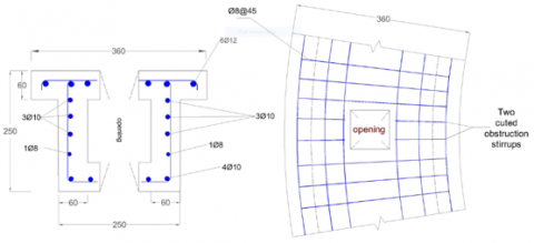
Table 5 shows circular beam specimens CB1.V60- CB6.T60.S2 designation. six semi-circular continuous curved box beams were designed in accordance with [38-40], consisting of two spans that are simply supported at the ends and a roller that offers support in the middle, with a radius of 1150 mm measured from the center line of the box beam's cross section, and having cross section of dimensions 250 mm overall depth and 250 mm width with a top flange width 360 mm, see Figure 1(a). The cross section of the beam includes hole with dimensions (130×130) mm to represent a box beam along the beam length, as shown in Figure 1(a). All beams' ends protruded 50 mm beyond the edge support's centerlines. These beams were examined by subjecting it to two point loads placed at mid of each span (angle 45°). Steel reinforcement (6Ø12) mm deformed bars were provided for top negative moment regions, (4Ø10) mm for bottom positive moment regions and (6Ø10+2 Ø8) mm as longitudinal torsion reinforcement with clear cover of 20 mm. The closed stirrups of Ø8 mm reinforcing bar were distributed at 90 mm center to center from angle (0) to angle (40°), and distributed at 45 mm center to center from angle (40°) to angle (90°) along the beam length for each span, noting that the angle measured from exterior support toward the interior support. Six Beam Specimens had openings with dimensions of (80*80 mm), Figure 1(b-c) shows the details of cut of obstruction rebars at vertical opening of specimens (CB1.V60- CB3.V60.S2) and details of cut of obstruction rebars at transverse opening of specimens (CB4.T60- CB6.T60.S2), respectively. The location of opening through each span of beam was marked by angle measured from exterior support to the center of opening.
Table 5. Designation and details of tested circular beam specimens
|
Specimen Designation |
Direction of Opening |
Location of Opening |
Type of Strengthening |
|
CB1.V60 |
Vertical |
60° |
---- |
|
CB2.V60.S1 |
Vertical |
60° |
S1(Hybridization of Concrete Around Opening) |
|
CB3.V60.S2 |
Vertical |
60° |
S2(External CFRP Laminates Around Opening) |
|
CB4.T60 |
Transverse |
60° |
---- |
|
CB5.T60.S1 |
Transverse |
60° |
S1(Hybridization of Concrete Around Opening) |
|
CB6.T60.S2 |
Transverse |
60° |
S2(External CFRP Laminates Around Opening) |
(a)
(b)
(c)
Figure 1. Details of specimens (all units in millimeters): (a) Geometry and reinforcement of all specimens; (b) Details of cut of obstruction rebars at opening of specimen CB1.V60 - CB3.V60.S2; (c) Details of cut of obstruction rebars at opening of specimens CB4.T60 - CB6.T60.S2
(a)
(b)
(c)
(d)
Figure 2. Details of strengthening schemes (all units in millimeters): (a) specimen CB2.V60. S1; (b) specimen CB5.T60.S1; (c) specimen CB3.V60.S2; (d) specimen CB6.T60.S2
The strengthening schemes for specimens CB2.V60.S1 and CB5.T60.S1 aimed to restore the overall structural behavior. The Reactive Powder Concrete (RPC) was cast monolithically as a hybridization of concrete around opening for the entire section of the beam at a distance of 125 mm on both edges of vertical and transverse opening, as shown in Figure 2 (a-b).
The strengthening schemes for specimen CB3.V60.S2 aimed to restore the overall structural behavior. Utilizing U wrap of CFRP sheets of 0.17 mm thickness with 80 mm width for each side of the opening and U wrap of 120 mm width for each top and bottom chords of opening, as shown in Figure 2 (c), while for specimen CB6.T60.S2, U wrap of CFRP laminates of 0.17 mm thickness with 100 mm width on each side of the opening and U wrap of 120 mm width for each top and bottom chords of opening, as shown Figure 2 (d).
With regards to the effect of internal force on the opening, location of opening was kept constant for all specimens which under effect of maximum shear and torsion.
3.3 Test setup and procedure
(a)
(b)
(c)
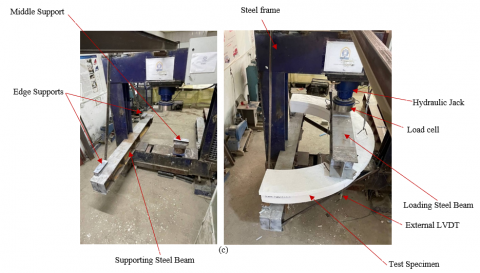
Figure 3. Test setup layout (a)Side view schematic drawing (b) Top view schematic drawing (c) photos
The Test setup, comprising supporting, loading conditions and instruments, is shown in Figure 3. All specimens were setup inside testing machine which has a capacity of (2000 kN). Each specimen was subjected to monotonic two-point loading, the outside ends of the supporting system were hinged, while the interior support was a roller., each load was applied at the mid-span of span. Four linear variable differential transformers (LVDTs) of (0.01 mm precision, 100 mm maximum capacity) to measure vertical deflection and twisting at mid-span, tow LVDTs one localized at exterior edge and the other at interior edge for each span of beam, see Figure 2 (a-c).
4.1 Crack pattern and failure modes
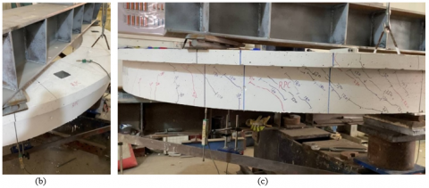
The photo of specimen CB1.V60 after failure is shown in Figure 4(a). This specimen includes vertical opening without restoring, positioned exactly at angle 60° measured from exterior support to the center of opening (between the applied loads and the internal support zone). At a load of around 50 kN, the first flexural crack was seen on the upper surface of highest negative moment (internal support). The first visible inclined cracks at the corners of lower and upper vertical openings at load 90 kN were created. The increasing of applied load was accompanied by rapid diagonal crack propagation at the corners of lower vertical opening, causing frame type failure mode at vertical opening at maximum ultimate load capacity was about 360.3 kN.
Figure 4(b-c) shows the photograph of specimen CB2.V60.S1 before and after failure, this specimen includes vertical opening with restoring by hybridization of concrete around opening using RPC cast monolithically, as illustrated in Figure 2(a). In this Specimen, flexural crack was first noticed at the upper face of the highest negative moment above the middle support with a load of around 59.2 kN. Fine corner cracks at lower vertical opening was noticed at load of 190 kN, while in upper vertical opening was appeared at 250 kN. Increasing in length, number and width of flexural and torsional-shear cracks were noticed as load as increase, while cracks in RPC zones maintain its length and width (no serious change) until failure. As mode of failure, the beam was failed due to flexural positive moment near midspan. The ultimate load capacity was about (427 kN), which was increased by about 18.5% when compared with specimen CB1.V60. theoretically, this is logical, as the presence of the RPC transferred the failure from the weak region were the specimen CB1.V60 failed to the mid-span of beam and eliminate the source of weakness due presence of opening. This is strictly speaking why the ultimate load capacity was increased.
Figure 4(d-e) shows the photograph of specimen CB3.V60.S2 before and after failure, this specimen includes vertical opening with restoring by U wrap of CFRP laminates around opening, as showed in Figure 2(c). Firstly, in a load of 60 kN, the first flexural crack appeared at the maximum negative moment zone above the interior support at the top tension region and at the maximum positive moment zone at the midspan. As load increased further, and due to confinements of CFRP laminates, diagonal crack was dilated at external corner of the lower vertical opening towards midspan was observed at load of about 150 kN, for upper vertical opening no diagonal cracks at corners was appeared until the load was reached 350 kN, also flexural and diagonal torsional-shear cracks was propagated (increase in number, length and width) through these increments. At stages of loading above 350 kN, corner cracks at the opening and torsional-shear cracks did not propagate when it approaches the CFRP laminates, it stops spreading until failure. because of the confinements of CFRP laminates. A frame type failure mode was happened at opening as a result of the torsional moment which cause deboning of CFRP laminates at load of 415.56 kN which was larger than the specimen CB1.V60 by about 15.3%.
Figure 4(f) shows the photograph of specimen CB4.T60 after failure. Specimen CB4.T60 includes transverse opening without restoring, positioned exactly at angle 60° measured from exterior support to the center of opening (in zone between the applied loads and internal support). Firstly, the Specimen CB4.T60 was gradually loaded till the initial crack appears when load reaches 50 kN at the skew corners (beam type) of transverse opening, also flexural torsional and shear cracks were observed. As load increased further, rapid widening of diagonal cracks at the corners of transverse opening led to a frame type failure mode at opening zone which occurred at ultimate load of 218 kN.
Figure 4(g-h) shows the photograph of specimen CB5.T60.S1 before and after failure, this specimen includes transverse opening with restoring by hybridization of concrete around opening using RPC cast monolithically, as illustrated in Figure 2(b). While the load was increased gradually, flexural crack was first appeared at the upper face of greatest negative moment above interior support with a load of about 65 kN. At load 80 kN, first flexural crack was initiated at maximum positive moment under applied load, while at load step of 90 kN first cracks in RPC zone at top and bottom skew corners of the transverse openings were noticed. Inclined torsional-shear cracks began to develop at region between the applied load and the middle support at load of 120 kN. As load increased further, torsional-shear cracks began to appear at load 170 kN in RPC zones around transverse openings. Increasing in length, number and width of flexural and torsional-shear cracks were noticed as load as increase, while cracks in RPC zones maintain its fine length and width (no considerable deformation) until failure because of high strength and ductility of RPC. At last, the beam was failed due to flexural positive moment near midspan at load of 512.65 kN, an increase was observed by about 135% when compared with the Specimen CB4.T60.
Figure 4(i-j) shows the photograph of specimen CB6.T60.S2 before and after failure. The specimen CB6.T60.S2 includes transverse opening with restoring by U wrap of CFRP laminates around opening, as showed in Figure 2(d). As usual, the beam was subjected to load till the flexural crack was noticed at a load of 60 kN at maximum negative moment zone above interior support. Also, inclined crack was observed in the top corner toward point of loading of the transverse opening owing to a high concentration of stresses at this corner at load of 70 kN, while flexural crack at maximum positive moment zone at midspan was initiated at load of 80 kN. At a load of approximately 110 kN, oblique torsional-shear cracks began to appear at zones between the point load and the mid support. Because of the confinements of CFRP laminates, corner cracks at the opening and torsional-shear cracks were initiated, but the rate of propagation and extension of these cracks was decreased, in another word the ultimate load capacity of specimen was increased. Finally, beam type failure mode was occurred as a result of a torsional moment which cause deboning of CFRP laminates at load of 301.54 kN. It can be concluded, that the ultimate load capacity was increase by about 38.3% as a comparison with Specimen CB4.T60.
Figure 4. Specimens before and after failure: (a) specimen CB1.V60; (b-c) specimen CB2.V60.S1; (d-e) specimen CB3.V60.S2; (f) specimen CB4.T60; (g-h) specimen CB5.T60.S1; (i-j) specimen CB6.T60.S2
4.2 Deformation response
Figure 5. (a) Load-Midspan Deflection Response for Specimens with Vertical Opening (b) Torsional Moment-Midspan Twisting Angle Response for Specimens with Vertical Opening
Figure 6. (a) Load-Midspan Deflection Response for Specimens with Transverse Opening (b) Torsional Moment-Midspan Twisting Angle Response for Specimens with Transverse Opening
Table 6. Service deformations of tested specimens.
|
Specimen Designation |
Service Deflection, ∆s (mm)* |
$\frac{\Delta s_{i}-\Delta s_{r}}{\Delta s_{r}} \times 100 \%(* *)$ |
Service Twisting, θS (Radian)×10-3 |
$\frac{\theta s_{i}-\theta s_{r}}{\theta s_{r}} \times 100 \%(* *)$ |
|
CB1.V60 |
8 |
---- |
12.5 |
---- |
|
CB2.V60.S1 |
6.94 |
-13.25 |
5.59 |
-55.28 |
|
CB3.V60.S2 |
9.85 |
23 |
10.88 |
-13 |
|
CB4.T60 |
6.43 |
---- |
10.53 |
---- |
|
CB5.T60.S1 |
9.86 |
53.3 |
9.4 |
-10.73 |
|
CB6.T60.S2 |
5.88 |
-8.6 |
10.28 |
-2.37 |
* (Pser.=0.65 Pult.) [43].
** $\Delta S_{r}$= Service deflection of the specimen with unrestored opening.
$\Delta S_{i}$ =Service deflection of the considered specimen.
In this experimental work, deformations represent a deflection and twisting at midspan of the circular beams. Deformations response of circular beams could be described by the load-midspan deflection relationships as well as torsional moment- midspan twisting relationships at service loads (approximately 65% of maximum load) as proposed in [42]. Figure 5(a-b) and Figure 6(a-b) represent the load-midspan deflection and torsional moment- midspan twisting response for specimens with a restored vertical and transverse opening, respectively, each compared to the that without restoring. Furthermore, the service deflection, twisting and their contrast percentages compared with the specimens without restoring for each direction were as shown in Table 6.
The specimens with vertical restored opening (CB2.V60.S1and CB3.V60.S2) showed a decrease and increase respectively in service midspan deflection by about (13.25) % and (23) %, noticed that this disparity corresponding to the increase in ultimate load compared with specimen containing opening without restoring. With regards to service midspan twisting, the specimens (CB2.V60.S1and CB3.V60.S2) showed a reduction (55.28) % and (13) %, respectively.
The specimens with transverse restored opening (CB5.T60.S1and CB6.T60.S2) showed an increase and decrease respectively in service midspan deflection by about (53.3) % and (8.6) %, noticed that the large increase for CB5.T60.S1 was corresponding to the immense increase in ultimate load compared with specimen containing opening without restoring (CB4.T60). With regards to service midspan twisting, the specimens (CB2.V60.S1and CB3.V60.S2) showed a reduction (10.73) % and (2.37) %, respectively.
4.3 Ductility
The ability to withstand inelastic deformations without losing load carrying capacity prior to failure is known as ductility. In the current study, ductility factors are assessed dividing the linear vertical displacement caused by maximum load $\Delta \boldsymbol{u}$ on that caused under service load $\Delta \boldsymbol{S}$ (approximately 65% of maximum load) as proposed in [44]. Ductility factors µ was defined as µ=($\frac{\Delta u}{\Delta s}$), which proposed in Ref. [44].
As shown in Table 7, examination results exhibit slight decrease in ductility of restored beams compared to the beam without restoring, except the specimen CB2.V60.S1 which showed a slight increase. It should be noted that this reduction corresponds to an increase in the restored specimen's ultimate load capacity when compared to the unrestored specimen.
Table 7. Ductility Factor of Tested Specimens
|
Specimen Designation |
Service Deflection, ∆s (mm)* |
Ultimate Deflection, ∆u (mm) |
Ductility Factor, $\mu\left(\frac{\Delta u}{\Delta s}\right)$ |
$\frac{\mu_{i}-\mu_{r}}{\mu_{r}} * \mathbf{1 0 0} \%^{(* *)}$ |
|
CB1.V60 |
8 |
14.14 |
1.77 |
---- |
|
CB2.V60.S1 |
6.94 |
12.6 |
1.82 |
2.82 |
|
CB3.V60.S2 |
9.85 |
17.25 |
1.75 |
-1.13 |
|
CB4.T60 |
6.43 |
13.4 |
2.08 |
---- |
|
CB5.T60.S1 |
9.86 |
19.26 |
1.95 |
-6.25 |
|
CB6.T60.S2 |
5.88 |
11.28 |
1.91 |
-8.17 |
*(Pser.=0.65 Pult.) [42].
**μi=Ductility of the considered restored specimen for specified direction.
μr=Ductility of the specimen without unrestored for specified direction.
4.4 Stiffness criteria
Table 8. Stiffness Criteria of Tested Specimens
|
Specimen Designation |
0.75 Pmax*(kN) |
Deflection at 0.75Pmax (mm) |
Stiffness, κ(kN/mm) |
$\frac{\boldsymbol{\kappa}_{\boldsymbol{i}}-\boldsymbol{\kappa}_{\boldsymbol{r}}}{\boldsymbol{\kappa}_{r}} \times$ 100%** |
|
CB1.V60 |
270.22 |
9.23 |
29.27 |
---- |
|
CB2.V60.S1 |
320.25 |
8.5 |
37.68 |
28.73 |
|
CB3.V60.S2 |
311.67 |
11.67 |
26.7 |
-8.78 |
|
CB4.T60 |
163.5 |
7.35 |
22.24 |
---- |
|
CB5.T60.S1 |
384.5 |
11.77 |
32.67 |
46.9 |
|
CB6.T60.S2 |
226.16 |
7.03 |
32.17 |
44.65 |
*max applied load.
**κi=Stiffness of the considered restored specimen for specified direction.
κr=Stiffness of the specimen without unrestored for specified direction.
The load required to produce unit deformation in a member is defined as stiffness κ, to assess the influence of load on deflection of curved beam. The slope of the secant drawn to each cycle in the hysterical curve at loading 0.75 times the maximum load of that cycle was measured as stiffness criteria as proposed in [45]. In this work Stiffness κ was defined as the ratio between the (0.75 of max applied load (Pmax), which represent the service load according to ACI code) and corresponding displacement, considering that each specimen subjecting to only one cycle of loading, Table 8 listed the variation in Stiffness κ, where κi is Stiffness of the considered beam with restored opening κr, Stiffness of the beam containing opening without restoring in specified direction. The stiffness of specimens with restored vertical opening (CB2.V60.S1 and CB3.V60.S2) showed an increase and decrease in stiffness, respectively by about (28.73% and 8.78 %), compared to that without restoring (CB1.V60). As specimens with strengthen transverse opening ( CB5.T60.S1 and CB6.T60.S2) exhibits a large increase in stiffness were about (46.9% and 44.65%), respectively, as comparison to that without strengthening (CB4.T60).
The results of an experiment using Reactive Powder Concrete or CFRP laminates as a restoring technique around opening on structural behavior of Horizontally Curved Box Beams were discussed in this work. The following conclusions may be drawn from the findings of this investigation.
1. A clear increase was observed in ultimate load capacity of specimens with restored vertical opening (CB2.V60.S1 and CB3.V60.S2) by about (18.5% and 15.3%) respectively compared to that without restoring (CB1.V60), while for specimens with restored transverse opening (CB5.T60.S1 and CB6.T60.S2) were about (135% and 38.3%) respectively, as comparison to that without restoring (CB4.T60). The efficacy of using RPC hybridization or CFRP laminates as restoring technique can be noted. With regards to the mode of failure, no alteration was observed in specimen CB3.V60.S2, while for specimens CB2.V60.S1and CB5.T60.S1 with RPC hybridization were conversion from frame-type failure mode of specimens CB1.V60 and CB4.T60, respectively to flexural failure at positive moment near midspan. The mode of failure of specimen CB6.T60.S2 was converted to beam type failure at opening.
2. As Service mid-span deflection response, no obvious picture for specimens with restored opening, It ranged between increase and decrease when compared with the specimens without restoring. The service mid-span twisting was positively affected (decreased) for all restored specimens (CB2.V60.S1, CB3.V60.S2, CB5.T60.S1 and CB6.T60.S2) by about (55.28%, 13%, 10.73% and 2.37%) when compared with the specimens without restoring for vertical and transverse directions, respectively.
3. With regards to ductility, there is no clear picture as the results differ between a slight increase and decrease as listed in Table 7, it can be noted that no significant effect of utilizing RPC hybridization and CFRP laminates as restoring techniques on the ductility of curved beams.
4. A considerable increase in stiffness can be observed for all restored specimens ( CB2.V60.S1, CB5.T60.S1 and CB6.T60.S2) by about (28.73%, 46.9% and 44.65%) respectively, except the stiffness of specimen CB3.V60.S2 which exhibits a slight decrease (8.78%) corresponding to large increase in subjecting load, as comparison to that without restoring in specified direction. It can also be concluded, that using RPC hybridization gives better result as a restoring technique than CFRP laminates.
[1] Gupta, P.K., Singh, K.K., Mishra, A. (2010). Parametric study on behaviour of box-girder bridges using finite element method. Asian Journal of Civil Engineering (building and housing), 11(1): 135-148.
[2] Wasti, S.T., Scordelis, A.C. (1984). Comparative structural behavior of straight, curved and skew reinforced concrete box girder bridge models. In Analysis and Design of Bridges, pp. 191-211. https://doi.org//10.1007/978-94-009-6122-7_7
[3] Kurian, B., Menon, D. (2007). Estimation of collapse load of single-cell concrete box-girder bridges. Journal of Bridge Engineering, 12(4): 518-526. https://doi.org/10.1061/(ASCE)10840702(2007)12:4(518)
[4] Arendts, J.G. (1969). Load distribution in simply supported concrete box girder highway bridges. Iowa State University.
[5] Razaqpur, A.G., Nofal, M., Mirza, M.S. (1989). Nonlinear analysis of prestressed concrete box girder bridges under flexure. Canadian Journal of Civil Engineering, 16(6): 845-853. https://doi.org/10.1139/l89-127
[6] Luo, Q.Z., Tang, J., Li, Q.S. (2003). Calculation of moments on top slab in single-cell box girders. Journal of Structural Engineering, 129(1): 130-134. https://doi.org/10.1061/(ASCE)07339445(2003)129:1(130)
[7] Subramani, T., Subramani, M., Prasath, K. (2014). Analysis of three dimensional horizontal reinforced concrete curved beam using Ansys. International Journal of Engineering Research and Applications, 4(6): 156-161.
[8] Al-Tameemi, H.A., Ali, A.P.D.A.Y., Attiyah, A.N. (2010). Three-dimensional nonlinear finite element analysis of reinforced concrete horizontally curved deep beams. Journal of Babylon University/Engineering Sciences, 18(1): 1-17.
[9] Al-Mutairee, H.M.K. (2013). Effect of non-uniform distribution of longitudinal reinforcement on the behavior of reinforced concrete horizontally curved beams with fixed-ends. J. Univ. Babylon, 21(3): 826-838.
[10] Badawy, H.E., McMullen, A.E., Jordaan, I.J. (1977). Effect of shear on collapse of curved beams. Journal of the Structural Division, 103(9): 1849-1866. https://doi.org/10.1061/JSDEAG.0004725
[11] Chu, K.H., Thelen, A. (1963). Plastic analysis of circular balcony girders. Journal of the Structural Division, 89(6): 159-186. https://doi.org/10.1061/JSDEAG.0000999
[12] Hsu, T.T., Inan, M., Fonticiella, L. (1978). Behavior of reinforced concrete horizontally curved beams. In Journal Proceedings, 75(4): 112-123.
[13] Jordaan, I.J., Khalifa, M.M., McMullen, A.E. (1974). Collapse of curved reinforced concrete beams. Journal of the Structural Division, 100(11): 2255-2269. https://doi.org/10.1061/JSDEAG.0003931.
[14] Khalifa, M.M. (1972). Collapse of reinforced concrete beams curved in plan (Master's thesis, Engineering). University of Calgary, Calgary, AB. https://doi.org/10.11575/PRISM/15252
[15] Mansur, M.A., Rangan, B.V. (1981). Study of design methods for reinforced concrete curved beams. In Journal Proceedings, 78(3) 226-254.
[16] Burton, K.T. (1965). Influence of embedded service ducts on the strength of continuous reinforced concrete T-beams. In Journal Proceedings, 62(10): 1327-1344.
[17] Dalal, M.S. (1969). Behavior and design of opening reinforced concrete T-Beams. Ph.D. Thesis, University of Taxas Austin, U.S.A.
[18] Hanson, J.M. (1969). Square openings in webs of continuous joists. Portland Cement Assoc R&D Lab Bull, l-14.
[19] Jindal, R.L. (1976). Behavior of reinforced concrete rectangular beam having large openings. Zanco Sul University, 2: 11-25.
[20] Mansur, M.A., Hasnat, A. (1979). Concrete beams with small opening under torsion. Journal of the Structural Division, 105(11): 2433-2447. https://doi.org/10.1061/JSDEAG.0005286
[21] Mansur, M.A., Alwis W.A.M. (1984). Reinforced fiber concrete deep beams with web opening. The International Journal of Cement Composites and Lightweight Concrete, 4: 263-271.
[22] Mansur, M.A., Tan, K.H., Lee, S.L. (1984). Collapse loads of R/C beams with large openings. Journal of Structural Engineering, 110(11): 2602-2618. https://doi.org/10.1061/(ASCE)07339445(1984)110:11(2602)
[23] Mansur, M.A., Paramasivam, P. (1984). Reinforced concrete beams with small opening in bending and torsion. In Journal Proceedings, 81(2): 180-185.
[24] Mansur, M.A., Tan, K.H., Lee, S.L. (1985). Design method for reinforced concrete beams with large openings. In Journal Proceedings, 82(4): 517-524.
[25] Mansur, M.A., Lee, Y.F., Tan, K.H., Lee, S.L. (1991). Tests on RC continuous beams with openings. Journal of Structural Engineering, 117(6): 1593-1606. https://doi.org/10.1061/(ASCE)0733-9445(1991)117:6(1593)
[26] Mansur, M.A. (1992). Deflections of reinforced concrete beams with web openings. In ACI Structural Journal, 4: 391-397.
[27] Mansur, M.A. (1998). Effect of openings on the behaviour and strength of R/C beams in shear. Cement and Concrete Composites, 20(6): 477-486. https://doi.org/10.1016/S0958-9465(98)00030-4
[28] Mansur, M.A., Tan, K.H. (1999). Concrete Beams with Openings: Analysis and Design, 20. CRC Press.
[29] Mansur, M.A. (2006). Design of reinforced concrete beams with web openings. In Proceedings of the 6th Asia-Pacific Structural Engineering and Construction Conference, pp. 104-120.
[30] Nasser, K.W., Acavalos, A., Daniel, H.R. (1967). Behavior and design of large openings in reinforced concrete beams. In Journal Proceedings, 64(1): 25-33.
[31] Patel and Saksena. (2013). Experimental of Reinforced Concrete Beams with Web Opening. International Journal of Advanced Engineering Research and Studies, Vol. II//Issue III 66-68.
[32] Salam, S.A. (1977). Beams with openings under different stress conditions. In Conference on Our World in Concrete and Structures, Singapore, pp. 25-26.
[33] Somes, N.F., Corley, W.G. (1974). Circular openings in webs of continuous beams. Special Publication, 42: 359-398.
[34] Tan, K.H., Mansur, M.A., Huang, L.M. (1996). Reinforced concrete T-beams with large web openings in positive and negative moment regions. Structural Journal, 93(3): 277-289.
[35] Mansur, M.A., Tan, K.H., Wei, W. (1999). Effects of creating an opening in existing beams. Structural Journal, 96(6): 899-905.
[36] Ahmed, A., Fayyadh, M.M., Naganathan, S., Nasharuddin, K. (2012). Reinforced concrete beams with web openings: A state of the art review. Materials & Design, 40: 90-102. https://doi.org/10.1016/j.matdes.2012.03.001
[37] Ali, A., Hemzah, S.A. (2014). Nonlinear analysis for behavior of RC horizontally semicircular curved beams with openings and strengthened by CFRP laminates. International Journal of Scientific & Technology Research, 3(8): 136-145.
[38] Ali, A.Y., Ibrahim, A.A., Yousif, R.F. (2011). Analysis of reinforced concrete beams with openings and strengthened by (CFRP) laminates. Univ Babylon Mag, 19(3): 1098-1113.
[39] Abdalla, H.A., Torkey, A.M., Haggag, H.A., Abu-Amira, A.F. (2003). Design against cracking at openings in reinforced concrete beams strengthened with composite sheets. Composite Structures, 60(2): 197-204. https://doi.org/10.1016/S0263-8223(02)00305-7
[40] Hamza, B.H. (2013). Behavior of RC curved beams with openings and strengthened by CFRP laminates. Doctoral Dissertation.
[41] European federation of specialist construction chemicals and concrete systems (EFNARC). (2005). The European Guidelines for Self- Compacting Concrete; Specification, Production and Use 1-68.
[42] De Larrard, F., Belloc, A., Renwez, S., Boulay, C. (1994). Is the cube test suitable for high performance concrete? Materials and Structures, 27(10): 580-583. https://doi.org/10.1007/BF02473126
[43] American Concrete Institute. (2012). Guide to Simplified Design for Reinforced Concrete Buildings (for Buildings of Limited Size and Height, Based on ACI-318-11 and ACI IPS-1, Essential Requirements for Reinforced Concrete Buildings). ACI.
[44] Russell, J.S. (2003). Prestrectives in Civil Engineering, Commemorating the 150th Anniversary of the American Society of Civil Engineering, ASCE Publications, p.375.
[45] Muthuswamy, K.R., Thirugnanam, G.S. (2014). Structural behaviour of hybrid fibre reinforced concrete exterior Beam-Column joint subjected to cyclic loading. International Journal of Civil and Structural Engineering, 4(3): 262-273. https://doi.org/10.6088/ijcser.201304010026