Ildar Badretdinov* | Salavat Mudarisov | Eduard Khasanov | Salavat Akchurin
© 2022 IIETA. This article is published by IIETA and is licensed under the CC BY 4.0 license (http://creativecommons.org/licenses/by/4.0/).
OPEN ACCESS
This article presents the results of a study of the vibrations of the deck of a pneumatic sorting machine. The purpose of this work is to describe the design and technological parameters of the soundboard for the implementation of a mathematical model of the technological process of the grain sorting machine. A kinematic study of the flat hinge mechanism of the deck of a grain sorting machine has been carried out, for which all geometric dimensions are known and the laws of motion of the leading link-the electric drive of the deck based on an asynchronous electric motor – have been determined. As a result, the following were determined: kinematic modes of deck vibrations under various technological conditions; the laws of motion of all links of the deck mechanism, displacement, speed and acceleration of the driven links; a mathematical model of the kinematic scheme of the deck of a grain sorting machine driven by an asynchronous electric motor has been developed.
deck, grain cleaning machine, kinematic scheme, mathematical model, modelling, technological process, vibrations
The increase in the volume of the agricultural products, the improvement of their quality, their cost, and energy loss reduction are closely related to the development and use of high-performance machines, the efficiency of which is mostly determined by the drive used [1-3].
Among the technological processes of the agro-industrial complex, the separation of grain material takes up a large share of labor and electricity costs, due to the low productivity and large volume of sorted material coming to these machines. At the same time, the productivity and technological efficiency of separating machines have a decisive impact on the production capacity of enterprises, the output of finished products and their quality [2, 3].
The review of the studies of many scientists [4-6] allows concluding that separating machines with the vibrational movement of flat separating sieves are universal and widespread. Among them are swinging and vibrating separators, in which separation is carried out due to the gravity forces under the influence of vibrational forces that ensure the orientation of the separated particles relative to the sieve holes. The vibrational forces consist of the forces of violent and natural sieve and kinematic drive system vibrations [5-9]. Therefore, the more complex the kinematic drive scheme, the more factors that affect the efficiency of the process and are negatively and increasingly manifested when mechanical parts wear out or age [10-13].
The drive of the presented machines in the works [6, 7, 9, 14-16] is built based on a traditional elaborate scheme with a converter of rotating motion to reciprocating. The more complex the kinematic scheme of the machine drive, the higher the machine cost. Simultaneously, energy efficiency and reliability decrease due to many rubbing and wearing surfaces and metal consumption. The metal consumption is also increased due to inertial flywheels designed to level down periodic force impulses, which is confirmed by work of Vyngra et al. [17]. The high drive inertia provokes an increase in the drive acceleration duration, thus increasing energy losses.
Moreover, there is a chance that the electric drive will not be able to accelerate to the rated speed at all. In work of Yarullin et al. [18], it is proposed to design a vibration machine in which frequency and amplitude are adjusted with vibrator eccentric mass. In such machines, the amplitude is automatically adjusted with the frequency increase during the machine operation according to the hyperbolic law of the complex mechanical systems application. In this paper, the problem of starting is proposed to be solved by more complex kinematics, which means the use of additional spring-loaded antidebalances.
Since further development is impossible when using the classical scheme of sieve drives, in work of Aipov et al. [19], it is proposed to use two rotational vibrators with the same or different static moments. The sieve (screen) trajectory is characterized by two different rotation speeds of the drive eccentric-type vibrators. Laboratory research was made. The research results allowed developing the concept of building an industrial screen, in which the inclination of the sieves is relative to the level, the installation of the engines is relative to the sieve center, exciting force are generated by the engine, the engine speed. The novelty of the drive design presented in the paper consists only in complicating the kinematics by cascading two drives with rotary electric motors.
Research objective: to study the grain sorting machine deck's structural and technological parameters and vibration modes.
The Froude number is the most critical functional estimating parameter of the sorted grain material's movement on the sieve surface. It is expressed by the ratio of forces acting on the grain material moving along the deck, the sieve vibrations amplitude, and gravity force [5, 6, 20].
The dynamic oscillation scheme of the grain sorting machine deck is called an idealized set of solid bodies (frame, sieve, frame) with moments of inertia (mass), connected by elastic elements. At the same time, under the action of driving forces, the bodies of the dynamic scheme make vibrations, and are considered as the relative mobility of bodies formed along the axis or in the plane along which the vibrations of the working body occur. The main requirement, as a rule, for the dynamic scheme of the machine in question is to provide the necessary law of vibrations of the working body (body weight). At the same time, a lot of important roles is played by ensuring stability, balance, and the gain of the driving force.
Let's consider a calculation scheme for determining the coordinates of the nodal points of the kinematics of the deck of a pneumatic sorting table (for example, MOS-9) to calculate their speed of movement, the forces of inertia acting on the particles of grain material lying on the surface of the deck (Figure 1).
Figure 1. Design model of the pneumatic picking disk deck (MOS-9)
Note: 1-crank, 2-connecting rod, 3-deck, 4-suspensions
The considered dynamic scheme of the deck of the grain sorting machine is a single-mass (mass of the sieve mill) with a forced eccentric crank drive (resonant mode of operation). The main advantage of this scheme is high stability during the operation of the machine, the vibration amplitude of the working body does not change. But at the same time, there is also a disadvantage – unbalance, especially with an uneven supply of grain material entering the sorting. In this regard, it is necessary to rigidly fix the base of the machine. In most cases, to eliminate this drawback, in order to partially balance the dynamic loads coming to the eccentric shaft, unbalanced counterweights (loads) are installed, and in some designs, it serves as a second working body. The gain of the driving force in such machines is low, which significantly leads to significant loads in the drive [8, 21, 22].
Let Ok be the control points coordinates, k = 0, 1, 2 (Figure 1). Point A at time t has coordinates:
$x_{0}=R \cdot \cos \omega t$
$y_{0}=R \cdot \sin \omega t$ (1)
where, R is the length of the crank rotating round the radial circle.
Find the coordinates of points B and C using the following algorithm:
a) First, find the coordinates of point B from the conditions:
$\left\{\begin{array}{l}A B=L_{1} \\ O_{1} B=L_{2}\end{array}\right.$ (2)
Note that in this case, the system can have either two, one, or no solutions depending on the parameters L1, L2, R, t. We assume that the numbers L1, L2, and R are chosen so that for any t, the system has a solution.
b) Find the coordinates of point C from the coordinates of the already found point B from the system:
$\left\{\begin{array}{c}B C=L_{3} \\ O_{2} C=L_{4}\end{array}\right.$ (3)
In such a case, the previous paragraph's remark regarding the existence of a solution and the choice of a single solution is fair enough.
Speed of point A. $V_{A}=\omega \cdot O A$.
where the following formula determines the crank angular rate (for the MOS-9 machine, after the belt drive from the asynchronous electric motor, the crank rotation speed is n=500 rpm (Figure 2)):
$\omega=\frac{\pi \cdot n}{30}=\frac{3.14 \cdot 500}{30}=52.35 \mathrm{~s}^{-1}$
Speed of point B:
$\left\{\begin{array}{l}\overrightarrow{V_{B}}=\overrightarrow{V_{A}}+\overrightarrow{V_{A B}} \\ \overrightarrow{V_{B}}=\overrightarrow{V_{O 1}}+\overrightarrow{V_{B O 1}}\end{array}\right.$ (4)
Speed of point C:
$\left\{\begin{array}{l}\overrightarrow{V_{C}}=\overrightarrow{V_{B}}+\overrightarrow{V_{B C}} \\ \overrightarrow{V_{C}}=\overrightarrow{V_{O 2}}+\overrightarrow{V_{C O 2}}\end{array}\right.$ (5)
Acceleration of point A at a constant angular rate aA=ω2∙OA.
Acceleration of point B:
$\left\{\begin{array}{c}\overrightarrow{a_{B}}=\overrightarrow{a_{A}}+\overrightarrow{a_{A B}^{n}}+\overrightarrow{a_{A B}^{\tau}} \\ \overrightarrow{a_{B}}=\overrightarrow{a_{O 1}}+\overrightarrow{a_{B O 1}^{n}}+\overrightarrow{a_{B O 1}^{\tau}}\end{array}\right.$ (6)
where, the normal acceleration is $a_{A B}^{n}$:
$a_{A B}^{n}=\frac{V_{A B}^{2}}{A B}$ (7)
Acceleration of point C:
$\left\{\begin{array}{c}\overrightarrow{a_{C}}=\overrightarrow{a_{B}}+\overrightarrow{a_{B C}^{n}}+\overrightarrow{a_{B C}^{\tau}} \\ \overrightarrow{a_{C}}=\overrightarrow{a_{O 2}}+\overrightarrow{a_{B O 2}^{n}}+\overrightarrow{a_{B O 2}^{\tau}}\end{array}\right.$ (8)
where, the normal accelerations are $a_{B C}^{n}$ and $a_{B O 2}^{n}$:
$a_{B C}^{n}=\frac{V_{B C}^{2}}{B C}$ and $a_{B O 2}^{n}=\frac{V_{B O 2}^{2}}{B O 2}$ (9)
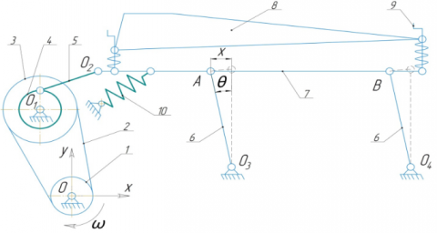
Figure 2 shows the calculation scheme for calculating the motion speeds and accelerations, the inertial forces acting on the sorted material. The presented vibration system of the grain sorting machine deck is a "hybrid" of a mathematical and spring pendulum. The deck is a link of the parallel four-link mechanism O3AVO4. The sieve pan is mounted on suspensions 6 with a length of l, and a deck 8 is attached to the sieve pan so that tilt angle 9 and cross angle of inclination can be adjusted. Elastic elements 10 (springs) are placed at an angle to the plane of the deck frame. In the equilibrium position, the suspensions are located at an angle of 15° from the vertical, and the springs are not deformed. The angle of inclination α determines deck plane setting AB to the horizontal (in this particular case α=7°).
Figure 2. Design model of the pneumatic picking disk deck (MOS-9)
Note: 1 – electric motor, 2 – belt drive, 3 – pulley kit, 4 – eccentric, 5 – connecting rod, 6 – suspension, 7 – deck frame, 8 – the deck of the pneumatic picking disk, 9 – adjustment of the longitudinal inclination angle, 10 – elastic elements
Let ai,x and bi,y be the coordinates of the fixed control points Oi, i = 1, 2, 3, 4 (Figure 2). The right-handed Cartesian coordinate system is taken as a reference system with the coordinate origin at the drive point O of the deck Fx(t). The deck nodal points are dotted to compose equations of geometric constants, the trajectories of which are known: А and В. These points move round radial circles l = О2А = О3В. Point A lies both in crank O2A and connecting rod AB. Point B lies both in crank O3B and connecting rod AB.
When deflected from the equilibrium position by an angle θ the deck is set into vibration, which is due to a positive horizontal direction of the exciting force F(t) created by an asynchronous electric motor 1 using a belt drive 2 and an eccentric shaft 4 through a connecting rod 5. If x is the linear displacement of the deck from the equilibrium along an arc with a radius equal to the length l of the suspensions l, its angular displacement is θ = x/l (Figure 2).
When the deck is deflected from the equilibrium, a rotational moment M occurs and tends to return it to the equilibrium position.
$M=J \varepsilon$ (10)
where, J=ml2 is the inertial moment, $\varepsilon=\frac{d^{2} \theta}{d t^{2}}$ is the angular acceleration.
The rotational movement M is produced by the forces of elasticity, gravity, inertia and resistance.
Deck vibration dynamic equation at small deviations θ under the action of a disturbing force force $\mathrm{F}(\mathrm{t})=\mathrm{F} \cdot \cos \omega t$ created by an electric motor:
$\begin{aligned} m l^{2} \cdot \frac{\mathrm{d}^{2} \theta}{\mathrm{dt}^{2}}=-\mathrm{mgl} & \\ & \cdot \sin \theta-\mathrm{kl}^{2} \\ & \cdot \sin \theta \cdot \cos \theta-\mathrm{f} \cdot \frac{\mathrm{d} \theta}{\mathrm{dt}} \cdot \mathrm{l}^{2}+\mathrm{F}(\mathrm{t}) \end{aligned}$ (11)
where, k is the stiffness coefficient, N/m, g is the gravity acceleration, m/s2, f is the resistance coefficient:
$\begin{aligned} \frac{d^{2} \theta}{d t^{2}}=-\frac{g}{l} \cdot \sin \theta &-\frac{k}{m} \\ & \cdot \sin \theta \cdot \cos \theta-\frac{f}{m} \cdot \frac{d \theta}{d t}+\frac{F(t)}{m l^{2}} \end{aligned}$ (12)
This second-order nonlinear differential equation is not integrated in ordinary functions. Taking into account small deviations θ and expanding sin θ by its Taylor series expansion:
$\sin \theta=\theta-\frac{\theta^{3}}{3 !}+\frac{\theta^{5}}{5 !}-\cdots$
as well as ignoring the first-order expansion terms, a second order nonhomogeneous differential equation with constant coefficients can be obtained:
$\frac{\mathrm{d}^{2} \theta}{\mathrm{dt}^{2}}+\left(\frac{\mathrm{g}}{\mathrm{l}}+\frac{\mathrm{k}}{\mathrm{m}}\right) \cdot \theta+\frac{\mathrm{f}}{\mathrm{m}} \cdot \frac{\mathrm{d} \theta}{\mathrm{dt}}=\frac{\mathrm{F}(\mathrm{t})}{\mathrm{ml}^{2}}$ (13)
If the angle θ is denoted by moving x, then
$\frac{\mathrm{d}^{2} \mathrm{x}}{\mathrm{dt}^{2}}+\left(\frac{\mathrm{g}}{\mathrm{l}}+\frac{\mathrm{k}}{\mathrm{m}}\right) \cdot \mathrm{x}+\frac{\mathrm{f}}{\mathrm{m}} \cdot \frac{\mathrm{dx}}{\mathrm{dt}}=\frac{\mathrm{F}(\mathrm{t})}{\mathrm{ml}^{2}}$ (13*)
Symbol $\frac{\mathrm{f}}{\mathrm{m}}=2 \beta$, where β is the attenuation coefficient, $\omega_{0}=\sqrt{\frac{g}{l}+\frac{k}{m}}$ is the circular vibration frequency, can be used. Vibration period $T=2 \pi \sqrt{\frac{m l}{k l+m g}}$. The damped vibrations frequency $\omega_{z}=\sqrt{\omega_{0}{ }^{2}-\beta^{2}}$ has a physical meaning at $\omega_{0} \geq \beta$.
The left part of the expression (13*) is a second-order linear differential equation that describes damped free vibrations. The right expression part, which depends on time, is the driving force.
For finding the law of the deck motion, it is necessary to solve this equation taking into account certain initial conditions: t=0; х = х0; $\frac{d x}{d t}=v_{0}$; The sum of two functions is the general solution of such an equation:
$x(t)=x_{1}(t)+x_{2}(t)$ (14)
where, x1(t) is the general solution of the homogeneous equation (left part (13*)), x2(t) is, respectively, the specific solution of the inhomogeneous equation (right part (13*)).
A general solution of the left-hand side (13*), which is a damped vibration that disappears over time, is:
$\mathrm{x}_{1}=\mathrm{C}_{1} \sin \omega \mathrm{t}+\mathrm{C}_{2} \cos \omega \mathrm{t} \equiv \mathrm{C} \sin (\omega \mathrm{t}+\gamma)$$\left(C_{1}=\right.$ const,$C_{2}=$ const,$C=$ const,$\gamma=$ const $)$ (15)
where, (C = const, γ =const) are the integration constants, is the amplitude of the deck free vibrations, ( is the phase of the rolling mill vibrations, γ is the phase of the initial vibration. Or
$\left.x_{1}\right|_{t \rightarrow \infty}=\lim _{t \rightarrow \infty}\left(A \cdot e^{-\beta t} \sin \left(\sqrt{\omega_{0}^{2}-\beta^{2}} t+\gamma\right)\right)=0$ (16)
The steady-state deck vibrations consist only of violent vibrations under the exciting force's action, which is determined in the right part of the expression (13*). The specific solution of this equation must be found in the form:
$x_{2}=B \sin (\delta t+\mu)$ (17)
where, B is the amplitude of the violent vibration, $B=\frac{F(t)}{m \sqrt{\left(\omega_{0}^{2}-\delta^{2}\right)^{2}+4 \beta^{2} \delta^{2}}} ; \quad \sin \mu=\frac{2 B m \beta \delta}{F(t)}$; $\cos \mu=\frac{\operatorname{Bm}\left(\omega_{0}^{2}-\delta^{2}\right)}{\mathrm{F}(\mathrm{t})}$;$\delta$ is the frequency of the violent vibrations; μ is the angle that determines the phase displacement of violent vibrations and the exciting force.
According to the standard method applying the Mathcad program, the practical implementation of the model is carried out using the numerical quartic Runge-Kutta method.
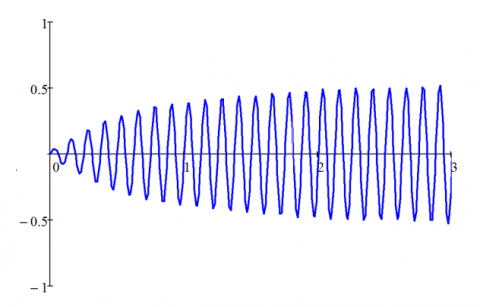
Figure 3. Graph of the changes in the deck vibrations of a grain sorting machine
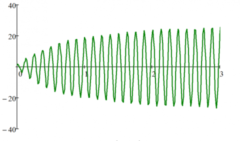
Figure 4. Graph of the change in the deck speed of a grain sorting machine
The trajectories of the links speed and accelerations received according to the modeling and calculations performed using Mathcad program are presented in Figures 3-6.
Figure 3 shows that the deck vibrations (harmonic) begin and increase under the exciting force F(t) created by an asynchronous electric motor. They stabilize in t = 3s going into a steady-state mode.
Analyzing Figure 4, based on the results of the numerical solution, it was determined that the maximum speed of the grain sorting machine deck is 0.54 m/s.
On the existing designs of grain sorting machines, the speed value varies from 0.35 to 0.65 m/s.
Figure 5. Graph of changes in the grain sorting machine deck acceleration
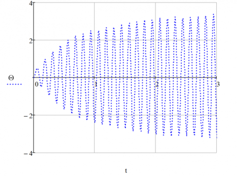
Figure 6. Graph of the change in the deck suspensions deflection angle θ
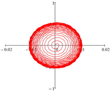
Figure 7. Curve of the phase trajectory of the grain sorting machine deck
The acceleration developed by the deck is 27.4 m/s2 (Figure 5). The recommended parameters and modes of oscillation of the sieves of grain cleaning machines from the conditions of the technological process of sorting are: the minimum acceleration developed by the sieve, at which the movement of grain material down the surface of the sieve should be provided is from 3 to 5 m/s2, the upward movement is from 6 to 8 m/s2, as well as separation from the surface at 70 to 80 m/s2, while the acceleration developed by the deck of the grain sorting machine reaches (1.5...3)g.
Figure 6 shows that the deck performs vibrations, and the change in the suspension's deflection angle relative to the initial axis varies within$-3.35^{0} \leq \theta \leq 3.47^{0} \mathrm{~s} .$.
The phase curve (Figure 7) clearly shows the speed jumps, leading to an increase in the vibrations' amplitude. Overtime (steady-state mode), the phase curve approaches a set of lines (attractor).
Consider energy relations.
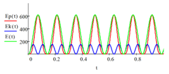
Figure 8. Graph of the change in the kinetic, potential, total energy of the system
Figure 8 shows the results of calculating the potential Ep(t), kinetic Ek(t), and total energy E(t) = Ep(t) + Ek(t).
It can be seen from the Figure 8 that the kinetic energy fluctuates with twice the circular frequency with respect to the vibrations of the lattice mill. When the potential energy is maximum, then at this time the kinetic energy is minimal, and vice versa. The oscillatory process of the lattice mill under consideration is explained by the transition of one type of energy to another. Thus, the energy relations in the system are decisive. In our case, they reflect the law of conservation of energy.
A mathematical model of the kinematic scheme of the grain sorting machine deck driven by an asynchronous electric motor has been developed. The deck vibrations' nature has been defined, and the vibration displacement, speed, and acceleration graphs have been constructed. The maximum deck speed was 0.54 m/s, and the acceleration developed by the deck varies in the range of 26.4...27.4 m/s2. During the deck vibrations, the angles of suspensions on which the deck is attached, deviate from the initial axis by an angle $\in\left[-3.35^{0} ; 3.47^{0}\right]$.
The proposed method of simulation of grain cleaning machines with a screen cleaning system makes it possible to study the drive mechanism kinematics and the process of separation with the help of flat vibrating working bodies, to analyze the degree of contact of particles of grain heap components with the screen, to identify problem areas and improve the design and technical parameters of the screen shoe of any grain cleaning machine. The developed model can be used repeatedly. Thus, there is no need for investment and verification of laboratory tests. The correct operating modes of the separation process for different crops can be found, and production recommendations can be given.
[1] Badretdinov, I., Mudarisov, S., Lukmanov, R., Ibragimov, R., Permyakov, V., Tuktarov, M. (2020). Mathematical modeling and study of the grain cleaning machine sieve frame operation. INMATEH – Agricultural Engineering, 60(1): 19-28. https://doi.org/10.35633/inmateh-60-02
[2] Mudarisov, S.G., Badretdinov, I.D. (2008). Improvement of technological lines for post-harvest grain processing in farms. In: Materials of the XLVII International Scientific and Technical Conference Dedicated to the 100th Anniversary of the Birth of I.E. Ullman “Achievements of Science to Agro-Industrial Production”, pp. 28-33.
[3] Mudarisov, S.G., Rakhimov, Z.S., Badretdinov, I.D., Akbatyrov, A.V., Farkhutdinov, I.M. (2009). Modernization of technological lines of grain processing taking into account economic conditions. In: Scientific support of sustainable functioning and development of agriculture. Proceedings of All-Russian Scientific and Practical Conference with International Participation (in the Framework of the 19th International Specialized Exhibition “AgroComplex-2009”), pp. 122-126.
[4] Căsăndroiu, T., Popescu, M., Voicu, G. (2009). A developing a mathematical model for simulating the seeds separation process on the plane sieves. Scientific Bulletin UPB, Series D, 71(3): 17-28.
[5] Dorokhov, A., Khamyev, V., Lepeshkin, K. (2018). Modernization of grinding machines of grain cleaning machines. MATEC Web of Conferences, 224: 05009. https://doi.org/10.1051/matecconf/201822405009
[6] Steponavičius, D., Špokas, L., Petkevičius, S. (2008). The influence of position of the first straw walkers section on grain separation. Agronomy Research, 6: 377-385.
[7] Ma, L., Song, X., Wang, H., Xu, X., Han, T., Guo, H. (2018). Screening kinematics analysis of cleaning organs and extractives. IOP Conference Series: Materials Science and Engineering, 452(4): 042123. https://doi.org/10.1088/1757-899X/452/4/042123
[8] Popov, I.P., Chumakov, V.G., Terentev, A.D. (2015). Reduction of drive power of screen shoe grain cleaning machines. Scientific and Technical Bulletin of St. Petersburg State Polytechnic University, 2(219): 175-181.
[9] Shevtsov, I.V., Beznosov, V.A. (2014). Drive unit of the screen shoes of grain cleaning machines. Agrarian Bulletin of the Urals, 2(120): 43-45.
[10] Bulat, P.V., Zasukhin, O.N., Upyrev, V.V., Silnikov, M.V., Chernyshov, M.V. (2017). Base pressure oscillations and safety of load launching into orbit. Acta Astronautica, 135: 150-160. https://doi.org/10.1016/j.actaastro.2016.11.042
[11] Giyevskiy, A.M., Orobinsky, V.I., Tarasenko, A.P., Chernyshov, A.V., Kurilov, D.O. (2018). Substantiation of basic scheme of grain cleaning machine for preparation of agricultural crops seeds. IOP Conference Series: Materials Science and Engineering, 327(4): 042035. https://doi.org/10.1088/1757-899X/327/4/042035
[12] Vasylkovskyi, O., Vasylkovska, K., Moroz, S., Sviren, M., Orozhyk, L. (2019). The influence of basic parameters of separating conveyor operation on grain cleaning quality. INMATEH–Agricultural Engineering, 57(1): 63-70.
[13] Savinyh, P., Sychugov, Y., Kazakov, V., Ivanovs, S. (2018). Development and theoretical studies of grain cleaning machine for fractional technology of flattening forage grain. In: Proceedings of 17th International Scientific Conference Engineering for Rural Development Engineering for Rural Development, pp. 124-130. https://doi.org/10.22616/ERDev2018.17.N156
[14] Al Said, N., Gorbachev, Y., Avdeenko, A. (2021). An unmanned aerial vehicles navigation system on the basis of pattern recognition applications–Review of implementation options and prospects for development. Software: Practice and Experience, 51(7): 1509-1517. https://doi.org/10.35741/issn.0258-2724.55.3.9
[15] Aradwad, P.P., Sinha, J.P., Arun Kumar, T.V., Yadav, R.S., Samuel, D.V.K. (2018). Development of solar powered screen cleaner. Indian Journal of Agricultural Sciences, 88(12): 1914-1919.
[16] Ravshanov, N., Sulaimonova, D. (2019). Model to study the technological process of separation of hard-to-separate granular mixtures and to adopt managerial decisions. Journal of Physics: Conference Series, 1260(10): 102014. https://doi.org/10.1088/1742-6596/1260/10/102014
[17] Vyngra, A.V., Avdeyev, B.A., Abdurakhmanov, R.F., Yenivatov, V.V., Ovcharenko, I.K. (2019). Mathematical model of start for a piston compressor electric drive of a ship refrigerator. In: Proceedings of the 2019 IEEE Conference of Russian Young Researchers in Electrical and Electronic Engineering. ElConRus. Saint Petersburg and Moscow, Russia, pp. 373-376. https://doi.org/10.1109/EIConRus.2019.8657190
[18] Yarullin, R., Aipov, R., Gabitov, I., Linenko, A., Akchurin, S., Safin, R., Mudarisov, S., Khasanov, E., Rakhimov, Z., Rakhimov, Z., Masalimov I. (2018). Adjustable driver of grain cleaning vibro-machine with vertical axis of eccentric masses rotation. Journal of Engineering and Applied Sciences, 13: 6398-6406. https://doi.org/10.3923/jeasci.2018.6398.6406
[19] Aipov, R., Linenko, A., Badretdinov, I., Tuktarov, M., Akchurin, S. (2020). Research of the work of the sieve mill of a grain-cleaning machine with a linear asynchronous drive. Mathematical Biosciences and Engineering, 17(4): 4348-4363. https://doi.org/10.3934/mbe.2020240
[20] Linenko, A.V., Gabitov, I.I., Baynazarov, V.G., Tuktarov, M.F., Aipov, R.S., Akchurin, S.V., Kamalov, T.I., Badretdinov, I.D., Leontiev, D.S., Vokhmin, V.S. (2019). The mechatronic module “linear electric drive – sieve boot” intelligent control system of grain cleaner. Journal of the Balkan Tribological Association, 25(3): 708-717.
[21] Chen, L., Li, D., Zhao, J. (2019). Control of a linear reciprocating switched reluctance motor for compressors. In: Proceedings of the 14th IEEE Conference on Industrial Electronics and Applications, ICIEA 2019. Xi'an, China, pp. 2003-2008. https://doi.org/10.1109/ICIEA.2019.8833814
[22] Dudarev, I., Zabrodotska, L., Satsiuk, V., Taraymovich, I., Olkhovskyi, V. (2020). Research on seed separation process on a gravity-cascade separator. INMATEH - Agricultural Engineering, 62(3): 173-180.