Sumit Kumar* | Amruta S. Dixit
© 2021 IIETA. This article is published by IIETA and is licensed under the CC BY 4.0 license (http://creativecommons.org/licenses/by/4.0/).
OPEN ACCESS
A miniaturized 2 x 1 multiple-input multiple-output (MIMO) antenna is presented in this paper. The designed antenna contains two circular patches with Complimentary Split-Ring Resonator (CSRR) that are etched in the ground which has a profound effect on antenna size reduction. It also helps in the reduction of isolation between two antennas. The maximum isolation between the two antennas is -84.62 dB at 2.8 GHz. The size of an antenna becomes more compact i.e., 40 x 20 x 1.6 mm3 after incorporating CSRR. The maximum gain of the designed antenna is 5.8 dBi at 4.3 GHz and the minimum reflection coefficient is -35.15 dB at 1.63 GHz. The operating band of an antenna is wide from 1.3 GHz to 4.3 GHz which covers Bluetooth, WiMax, and LTE applications. The proposed antenna is useful for various wireless applications.
Complimentary Split-Ring Resonator (CSRR), long term evolution (LTE) band, miniaturized, multiple-input multiple-output (MIMO)
MIMO is used in many wireless communications systems including ultra-wideband [1], Wireless LAN [2], WiMax [3], LTE [4, 5], Ka band [6] and 5G communications [7-10] for better performance, to reduce cost, to improve the data transfer speed, and to alleviate resource utilization. LTE is used in 4G technology and it uses MIMO technology for the improvement of radio spectrum efficiency, throughput, and handoff capabilities. MIMO uses a multipath phenomenon to pass signals from different angles in case of any obstacles and to eliminate the errors that occurred in multipath wave propagation. The multi-antenna system (MIMO) provides us a good quality signal for high data rates. The traditional wireless system uses a single antenna, but it may not provide high gain and wide bandwidth [11, 12]. Next, antenna arrays are developed to provide high gain and bandwidth [13-15]. The most important advantage of MIMO is that it allows beamforming which reduces signal interference [16]. Further, after incorporating MIMO, the channel capacity and can be increased [17]. Importantly, the MIMO technology plays a significant role in spectral efficiency improvement and data transmission in multi-antenna network [18].
The MIMO antenna is advantageous only if the level of mutual coupling among antenna elements is less. There are various mutual coupling reduction techniques to alleviate mutual coupling [19] and performance enhancement techniques [20]. The different mutual coupling reduction techniques are metamaterial [21], neutralization lines [22], defected ground structure (DRA) [23], CSRR [24], electromagnetic bandgap (EBG) [25], etc. These techniques are elaborated in detail in [26]. Also, after incorporating slot structures in the ground plane, mutual coupling gets enhanced [27-29].
According to Subhanrao Bhadade and Padmakar Mahajan [2], the mutual coupling is above 33 dB for the desired 5.49-6.024 GHz frequency range and it is achieved by using slots in the ground. Next, a two-port MIMO antenna for the UWB application is designed in Nie et al. [17] by using monopole and two structure shared Vivaldi antennas. In this, improved isolation of above 38 dB is obtained by implementing differential and orthogonal feeding. Moreover, the importance of CSRR in antenna size reduction is illustrated in Ref. [30]. In Ramzan and Topalli [30], the traditional square patch antenna size is reduced by 25% after incorporating CSRR in it. In Salhi et al. [31], an active square-shaped CSRR is incorporated in a circular patch by using varicap diodes to design a tri-band antenna for wireless communication. Further, in Ref. [32] a patch antenna with enhanced gain and bandwidth is implemented by using CSRR.
In this antenna design, we use multiple antenna techniques that help in increasing data throughput and range compared with the single antenna that works using the same radio transmit power. The multiple antenna designs increase antenna size which is not desirable for compact devices. If we will reduce the distance between antenna elements then it badly affects the mutual coupling which is also not desirable. To overcome these issues, the design of a compact 2 element MIMO antenna which consists of two similar circular patch antennas with CSRRs is proposed. The band that has been proposed is the LTE band which operates in the frequency range of 1.3-4.3 GHz. The dimensions of the antenna are 40 x 20 x 1.6 mm3. After the introduction section, antenna design is explained in detail. After that, the antenna results are elaborated in section 3 followed by the conclusion.
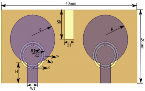
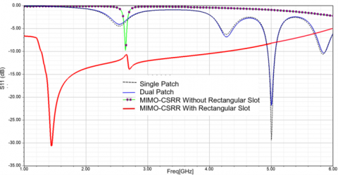
Figure 1 shows a circular patch antenna with CSRR. It is fabricated on the FR4 substrate which has a dielectric constant of 4.4 and a height of 1.6 mm. The FR4 substrate is selected because it is easily available and cost-effective. A step-by-step evolution process of the designed antenna is depicted in Figures 1(a), 1(b), and 1(c). At first, a single circular patch antenna was designed to operate at a 5 GHz frequency. In this, the substrate size is 40 mm x 50 mm, the radius of the circle is 16.55 mm, microstrip line width and length are 3 mm and 17 mm respectively. As depicted in Figure 2, the designed single patch resonates at 5 GHz. Its performance is enhanced by designing a 2 x 1 MIMO antenna as shown in Figure 1(b) which also resonates at 5 GHz as depicted in Figure 2. The size of the MIMO antenna is size is 80 mm x 50 mm which is large. But the desired operating frequency is 2.4 GHz which is achieved by incorporating CSRR and a rectangular slot in the ground plane. CSRR has a high filtering capability, which is used for reducing coupling. The antenna compactness (40 mm x 20 mm) is achieved by including CSRR based metamaterial plane.
In MIMO, the spacing between two elements is 8 mm to achieve good isolation. Next, the CSRR minimizes the resonating frequency from 5 GHz to 2.64 GHz as shown in Figure 2. The CSRR equivalent circuit is LC circuit. After incorporating CSRR in an antenna, it changes the overall inductance and capacitance of the antenna which in turn results in the change of resonance frequency. The microstrip line is used for feeding whose width and length are selected to match 50 Ω input impedance of a SubMiniature version A (SMA) connector. The rectangular slot of 8 mm x 2.75 mm size is added in between two antennas to operate an antenna in the 1.3 GHz to 4.3 GHz frequency range. The fabricated antenna is given in Figure 1 in which Figures 1(d) and 1(e) shows top and bottom patches of the proposed antenna design respectively. Antenna dimensions are finalized after antenna parameter optimization with the help of HFSS version 19 simulation software. Table 1 and Table 2 provide the dimensions of the designed antenna and CSRR respectively.
Further, Figure 1 proves the importance of CSRR in antenna miniaturization. Initially, 2 x 1 MIMO antenna size is 80 mm x 50 mm, but after incorporating CSRR in the ground plane the antenna size is alleviated to 40 mm x 20 mm. Further, as CSRR introduces resistance, capacitance, and inductance it affects the frequency response of an antenna. As depicted in Figure 2, single and dual patch circular antenna resonates at 5 GHz and after incorporating CSRR, the resonance frequency shifted to 2.64 GHz. Further, a rectangular slot in the ground plane reduces the lower cut-off frequency to 1.3 GHz and enhances the operating bandwidth which is in the range of 1.3 GHz to 4.3 GHz. Thus, overall performance of an antenna is improved after the introduction of CSRR and slot in the ground plane.
Table 1. Antenna dimensions
|
Descriptions |
Parameters |
Dimensions |
|
Patch radius |
R |
6.6 mm |
|
Height |
H |
6 mm |
|
Width |
Wf |
3 mm |
|
Slot height |
Sh |
8 mm |
|
Slot Width |
Sf |
2.75 mm |
(a)
(b)
(c)
(d)
(e)
Figure 1. Proposed Antenna Design (a) Single patch of 40 mm x 50 mm size (b) 2 x 1 MIMO of 80 mm x 50 mm size (c) 2 x 1 MIMO Antenna Structure with ground slot of 40 mm x 20 mm, (d) 2 x 1 MIMO Fabricated Antenna (Top view) and (e) 2 x 1 MIMO Fabricated Antenna (Bottom view)
Figure 2. Simulated reflection coefficient
Table 2. CSRR Dimensions
|
Descriptions |
Parameters |
Dimensions |
|
Inner radius of CSRR |
R1 |
3.1 mm |
|
Outer radius of CSRR |
R2 |
3.75 mm |
|
Ring width |
w |
0.45 mm |
|
Width between the rings |
k |
0.2 mm |
|
Slit width |
g |
0.5 mm |
High-Frequency Structure Simulator (HFSS version 19) is used to simulate the antenna and tested on Rohde and Schwarz ZVA24 vector network analyzer. The antenna dimensions are finalized after many iterations and sent for fabrication after achieving desired antenna performance parameters. Figure 3(a) is the reflection coefficient from both the ports of the designed antenna which depicts that the antenna operates in the band of 1.3 - 4.3 GHz and mutual coupling between two patches is reduced to -84.62 dB at 2.81 GHz. The mutual coupling is calculated by using equations 1 and 2. The CSRR gives negative permittivity and the equivalent circuit of CSRR is the LC circuit [29] which improves isolation at the resonance frequency. Over this frequency range, the value of the S11 is below -10 dB. The maximum reflection coefficient is -30.65 dB and it is obtained at 1.44 GHz.
$\mathrm{MC}_{\mathrm{ab}}=\exp \left(-\frac{2 \mathrm{x}_{\mathrm{ab}}}{\lambda}(\alpha+\mathrm{n} \pi)\right), \mathrm{a} \neq \mathrm{b}$ (1)
$\mathrm{MC}_{\mathrm{ab}}=1-\frac{1}{\mathrm{~N}} \sum_{\mathrm{a}} \sum_{\mathrm{a} \neq \mathrm{b}} \mathrm{MC}_{\mathrm{ab}}$ (2)
In above equations, $\mathrm{MC}_{\mathrm{ab}}$ is the mutual coupling, N is the number of antenna elements, $x_{a b}$ represents the distance between $a^{\text {th }}$ and $b^{\text {th }}$ antenna elements, and α controls the coupling level.
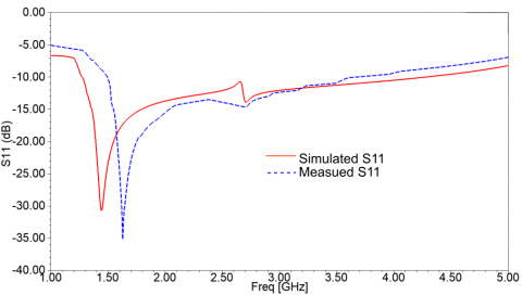
As plotted in Figure 4, the difference between measured and simulated results is minor. There is a little bit of difference in both the results due to manufacturing defects and cable losses. The fabricated antenna resonates at 1.6 GHz and gives -35.15 dB reflection coefficients whereas the simulated resonance frequency is 1.44 GHz and the corresponding reflection coefficient is -30.65 dB. The simulated operating frequency range is 1.3 GHz to 4.3 GHz whereas the measured frequency range is 1.5 GHz to 3.7 GHz. The gain of the 2 x 1 MIMO Antenna in the 3 - dimensional is shown in Figure 5 which shows that the gain is 5.81 dBi. The E and H planes are shown in Figure 6. It shows that all radiation patterns are ‘8’ shaped patterns and they are almost stable. Next, the simulated gain graph is shown in Figure 7. It shows that gain varies from 2.1 dBi to 5.8 dBi which is in the acceptable range.
Figure 3. Reflection coefficients and mutual coupling
Table 3 proves the importance of the designed and proposed antenna. The antenna dimensions are mentioned in terms of low operating grounded wavelength. In Refs. [28, 29, 33, 34] the antenna size is moderate but the mutual coupling is low. Next, a wide bandwidth antenna with improved mutual coupling is designed by Pramon et al. [35] but its antenna size is very large. A compact antenna for UWB application is designed in Ref. [36] but its mutual coupling is moderate. This table proves that the designed antenna is very compact with very good mutual coupling reduction and it is the best antenna for LTE band application.
Figure 4. Measured and Simulated S11
Figure 5. 3D gain plot of the MIMO with CSRR
Figure 6. Simulated radiation pattern of E (Red) and H plane (Blue) at (a) 1.3 GHz, (b) 2.5 GHz, (c) 3.5 GHz and (d) 4 GHz
Figure 7. Simulated gain versus frequency graph
Table 3. Comparison of proposed antenna performance Parameters with the other similar patch antennas
|
Ref. No. |
εr |
Dimensions (λ3) |
Mutual Coupling (dB) |
Frequency (GHz) |
|
[28] |
4.4 |
2.12 x 1.62 x 0.053 |
-32.79 |
4.75, 5.89, 6.74, 8.25, 9.82 |
|
[29] |
4.4 |
1.86 x 1.46 x 0.064 |
-32 |
5.8 |
|
[33] |
4.4 |
1.19 x 0.95 x 0.019 |
-50 |
1.7 - 3 |
|
[34] |
4.4 |
0.73 x 0.73 x 0.02 |
-47 |
3 - 12 |
|
[35] |
4.4 |
27.96 x 13.98 x 2.96 |
-81.4 |
20 - 40 |
|
[36] |
4.4 |
1.34 x 0.67 x 0.008 |
Not Given |
1.6 - 2.48 |
|
[37] |
4.4 |
3.46 x 1.73 x 0.018 |
-40 |
3.3 - 3.6 4.8 - 5 |
|
This Work |
4.4 |
0.36 x 0.18 x 0.014 |
-84.62 |
1.5 - 3.7 |
A 2 x 1 MIMO circular patch antenna with CSRR is presented in this paper. Simple circular patch 2 x 1 MIMO antenna size is 80 mm x 50 mm whereas the 2 x 1 MIMO with CSRR size is only 40 mm x 20 mm. Hence, the compact antenna can be designed by incorporating CSRR. Next, with the help of CSRR, the circular patch antenna acts like a bandpass filter operating in the band of 1.3 GHz - 4.3 GHz. CSRR also helps to improve mutual coupling between two designed circular patch antennas. There is a minor difference between measured and simulated results. The maximum mutual coupling between the two antennas is -84.62 dB at 2.8 GHz. As the designed antenna is compact, improved isolation, and wide bandwidth it can be used for Bluetooth, WiMAX, and LTE band applications.
|
MIMO |
multiple-input multiple-output |
|
CSRR |
Complimentary Split-Ring Resonator |
|
LTE |
long term evolution |
|
DRA |
defected ground structure |
|
EBG |
electromagnetic bandgap |
|
WLAN |
wireless local area network |
|
UWB |
ultra wideband |
|
HFSS |
High Frequency Structure Simulator |
|
Greek symbols |
|
|
Ω |
resistance |
|
λ |
wavelength |
[1] Raad, H.K. (2018). An UWB antenna array for flexible IoT wireless systems. Progress In Electromagnetics Research, 162: 109-121. https://doi.org/10.2528/PIER18060804
[2] Subhanrao Bhadade, R., Padmakar Mahajan, S. (2019). Circularly polarized 4×4 MIMO antenna for WLAN applications. Electromagnetics, 39(5): 325-342. https://doi.org/10.1080/02726343.2019.1619227
[3] El Yassini, A., Jallal, M.A., Ibnyaich, S., Zeroual, A., Chabaa, S. (2020). A miniaturized CPW-Fed reconfigurable antenna with a single-dual band and an asymmetric ground plane for switchable band wireless applications. Traitement du Signal, 37(4): 633-638. https://doi.org/10.18280/ts.370412
[4] Morsy, M.M. (2016). A printed wideband MIMO antenna system for GSM1800/1900, UMTS, WLAN2450, LTE2300/2500, and GPS Applications. Progress In Electromagnetics Research C, 70: 33-41. https://doi.org/10.2528/PIERC16093004
[5] Kurvinen, J., Kähkönen, H., Lehtovuori, A., Ala-Laurinaho, J., Viikari, V. (2018). Co-designed mm-wave and LTE handset antennas. IEEE Transactions on Antennas and Propagation, 67(3): 1545-1553. https://doi.org/10.1109/TAP.2018.2888823
[6] Farooq, U., Rather, G.M. (2019). Design and analysis of rectangular microstrip antenna (RMSA) for millimeter wave communication applications. Traitement du Signal, 36(5): 433-438. https://doi.org/10.18280/ts.360508
[7] Zhang, W., Weng, Z., Wang, L. (2018). Design of a dual-band MIMO antenna for 5G smartphone application. In 2018 International Workshop on Antenna Technology (iWAT), pp. 1-3. https://doi.org/10.1109/IWAT.2018.8379211
[8] Shevada, L., Raut, H.D., Malekar, R., Kumar, S. (2021). Comparative Study of different beamforming techniques for 5G: A Review. Inventive Communication and Computational Technologies, pp. 589-595. https://doi.org/10.1007/978-981-15-7345-3_50
[9] Sheikh, T.A., Bora, J., Hussain, A. (2019). Performance analysis of massive multi-input and multi-output with imperfect channel state information. Traitement du Signal, 36(4): 361-368. https://doi.org/10.18280/ts.360409
[10] Raut, H.D., Shevada, L., Malekar, R., Kumar, S. (2021). High gain wideband antennas for 5G applications: A review. Inventive Communication and Computational Technologies, pp. 777-787. https://doi.org/10.1007/978-981-15-7345-3_67
[11] Dixit, A.S., Kumar, S. (2020). The enhanced gain and cost‐effective antipodal Vivaldi antenna for 5G communication applications. Microwave and Optical Technology Letters, 62(6): 2365-2374. https://doi.org/10.1002/mop.32335
[12] Kumar, S., Dixit, A.S. (2021). A Bibliometric survey on antipodal Vivaldi antenna. Library Philosophy and Practice, pp. 1-25.
[13] Dixit, A.S., Kumar, S. (2020). A miniaturized antipodal Vivaldi antenna for 5G communication applications. In 2020 7th International Conference on Signal Processing and Integrated Networks (SPIN), pp. 800-803. https://doi.org/10.1109/SPIN48934.2020.9071075
[14] Bhadoria, B., Kumar, S. (2018). A novel omnidirectional triangular patch antenna array using Dolph Chebyshev current distribution for C-band applications. Progress in Electromagnetics Research M, 71: 75-84. https://doi.org/10.2528/PIERM18051402
[15] Dixit, A.S., Kumar, S., Urooj, S., Malibari, A. (2021). A highly compact antipodal Vivaldi antenna array for 5G millimeter wave applications. Sensors, 21(7): 2360. https://doi.org/10.3390/s21072360
[16] Dixit, A.S., Shevada, L.K., Raut, H.D., Malekar, R.R., Kumar, S. (2020). Fifth generation antennas: A bibliometric survey and future research directions. Library Philosophy and Practice (e-journal), 4575.
[17] Nie, L.Y., Lin, X.Q., Yang, Z.Q., Zhang, J., Wang, B. (2018). Structure-shared planar UWB MIMO antenna with high isolation for mobile platform. IEEE Transactions on Antennas and Propagation, 67(4): 2735-2738. https://doi.org/10.1109/TAP.2018.2889596
[18] Mehdaoui, Y., Malaoui, A., Gaga, A., El Alami, R., Mrabti, M. (2019). The efficiency of the CORDIC Operator in the MIMO MC-CDMA receiver. Math. Model. Eng. Probl, 6(1): 99-104.
[19] Kumar, S., Dixit, A.S., Malekar, R.R., Raut, H.D., Shevada, L.K. (2020). Fifth generation antennas: A comprehensive review of design and performance enhancement techniques. IEEE Access, 8: 163568-163593. https://doi.org/10.1109/ACCESS.2020.3020952
[20] Dixit, A.S., Kumar, S. (2020). A survey of performance enhancement techniques of antipodal Vivaldi antenna. IEEE Access, 8: 45774-45796. https://doi.org/10.1109/ACCESS.2020.2977167
[21] Srivastava, V.M. (2018). Comparative analyses for RCS of 10 GHZ patch antenna using shorted stubs metamaterial absorber. Journal of Engineering Science and Technology, 13(11): 3532-3546.
[22] Shevada, L.K., Raut, H.D., Malekar, R.R., Dixit, A.S., Kumar, S. (2021). A bibliometric survey on ultra wideband multiple input multiple output antenna with improved isolation. Libr, Philos, Pract, pp. 1-20.
[23] Jangid, K.G., Jain, P.K., Choudhary, N., Sharma, B., Saxena, V.K., Kulhar, V.S., Bhatnagar, D. (2018). U-shaped slots loaded patch antenna with defected ground plane for multiband modern communication systems. Journal of Engineering Science and Technology, 13(5): 1396-1410.
[24] Malekar, R.R., Shevada, L.K., Raut, H.D., Dixit, A.S., Kumar, S. (2020). MIMO antenna for Fifth Generation mm-Wave Applications: A Bibliometric Survey. Library Philosophy and Practice (e-journal), 4854: 1-21.
[25] Lakshmi, M.L.S.N.S., Madhav, B.T.P., KHAN, H., Pardhasaradhi, P. (2019). EBG loaded compact wide-notch band antenna with frequency reconfigurable characteristics. Journal of Engineering Science and Technology, 14(4): 1878-1892.
[26] Nadeem, I., Choi, D.Y. (2018). Study on mutual coupling reduction technique for MIMO antennas. IEEE Access, 7: 563-586. https://doi.org/10.1109/ACCESS.2018.2885558
[27] Hussain, R., Sharawi, M.S., Shamim, A. (2017). An integrated four-element slot-based MIMO and a UWB sensing antenna system for CR platforms. IEEE Transactions on Antennas and Propagation, 66(2): 978-983. https://doi.org/10.1109/TAP.2017.2781220
[28] Rao, P.S., Babu, K.J., Prasad, A.M. (2017). Compact multi-band MIMO antenna with improved isolation. Progress in Electromagnetics Research M, 62: 199-210. https://doi.org/10.2528/PIERM17090201
[29] Kumar, N., Kommuri, U.K. (2018). MIMO antenna mutual coupling reduction for WLAN using spiro meander line UC-EBG. Progress in Electromagnetics Research C, 80: 65-77. https://doi.org/10.2528/PIERC17101601
[30] Ramzan, M., Topalli, K. (2015). A miniaturized patch antenna by using a CSRR loading plane. International Journal of Antennas and Propagation. https://doi.org/10.1155/2015/495629
[31] Salhi, R., Labidi, M., Choubani, F. (2018). A design of multi-band antenna based on active metamaterials. Optical Materials, 84: 307-311. https://doi.org/10.1016/j.optmat.2018.07.025
[32] Islam, A.M., Emon, E.I., Ahmed, A. (2020). A metamaterial loaded microstrip patch antenna for lower 5G U-NII spectrum. Mathematical Modelling of Engineering Problems, 7(4): 556-562. https://doi.org/10.18280/mmep.070407
[33] Alieldin, A., Huang, Y., Boyes, S.J., Stanley, M. (2018). A reconfigurable broadband dual-mode dual-polarized antenna for sectorial/omnidirectional mobile base stations. Progress in Electromagnetics Research, 163: 1-13. https://doi.org/10.2528/PIER18050206
[34] Zhu, J., Li, S., Feng, B., Deng, L., Yin, S. (2015). Compact dual-polarized UWB quasi-self-complementary MIMO/diversity antenna with band-rejection capability. IEEE Antennas and Wireless Propagation Letters, 15: 905-908. https://doi.org/10.1109/LAWP.2015.2479622
[35] Pramon, S., Basuki, B.S., Syamsul, S.H. (2019). A compact design eight element multiple input multiple output millimeter-wave antenna. Journal of Engineering Science and Technology, 14(1): 265-278.
[36] Riaz, S., Zhao, X. (2018). An 8-element frequency-agile MIMO communication antenna system for CR front-end applications. Progress in Electromagnetics Research C, 84: 75-85. https://doi.org/10.2528/PIERC18031702
[37] Chen, L., Wang, D., Zhang, S., Xia, L., Jiang, S., Lan, S. (2019). A MIMO antenna array for 5G mobile terminals. In 2019 IEEE International Symposium on Antennas and Propagation and USNC-URSI Radio Science Meeting, pp. 1285-1286. https://doi.org/10.1109/APUSNCURSINRSM.2019.8888604