Faton Maliqi* | Bleron Klaiqi
© 2021 IIETA. This article is published by IIETA and is licensed under the CC BY 4.0 license (http://creativecommons.org/licenses/by/4.0/).
OPEN ACCESS
This paper considers the issue of selecting the optimal position where a Relay could be fixed to enable the communication between a Source and a Destination. Our analysis is focused on the case when Relay works on Demodulate-and-Forward (DMF) mode, due its simple nature in implementation. DMF Relay only demodulates the received signals from the Source without checking the integrity of the signals and it may happen that it forwards the erroneous signals toward the Destination. Since moving the Relay in different positions between the Source and the Destination brings different performances, we are interested to find the position at which the benefit of using the Relay is maximized. To help us find this optimal position analytically and numerically, we have introduced a criterion which relies on the trade-off between the demodulation errors on the channel S-R and the ability of the Relay to succeed on the transmission path R-D, where the theoretical analysis of the criterion matches perfectly with the simulation analysis. Moreover, in a scenario of having more than one Relay, this criterion helps us to choose the best instantaneous Relay for cooperation. The comparison of our proposed criterion with a referent criterion from the literature, has shown that our criterion outperforms the referent criterion.
cooperative communications, relay selection, fixed relay position, wireless networks, demodulate-and-forward (DMF)
Cooperative communications [1], where the communication between a Source and a Destination is assisted by a Relay, has been treated extensively in recent years. Most of the published articles consider the Relay to work either in Decode-and-Forward (DCF) mode [2] (where beside energy consuming concern, some complex algorithms need to be implemented on Relay), or either in Amplify-and-Forward (AF) mode [3] (where beside the amplification of the signal, it is amplified also the noise), but our analysis is focused on the case when Relay works in Demodulate-and-Forward (DMF) mode [4], which would be of great interest in contexts where energy efficiency at the Relay node is of great importance, such as in the Internet of Things. Possible applications of relaying in IoT can be found at low-power wireless access network (LPWAN) technologies such as SigFox, LoRa and NB-IoT [5]. Note that, Relay in DMF mode only demodulates (does not decode) the signal received from the Source, and then re-modulates and forwards it to the Destination. Due to the demodulation errors that may occur during the demodulation process on the Relay (without detecting the errors), it may happen that the Relay forwards some incorrect symbols toward the Destination. Therefore, the optimal position of the Relay needs to count for the trade-off between the demodulation errors on the channel S-R, and its ability to succeed on the remaining distance R-D.
In the context of cooperation, Relay could be a fixed node, i.e. in Wireless Local Area Networks (WLAN), a moving node, i.e. in Vehicular Ad-hoc Networks (VANET), or a combined node, i.e. in technologies such as 3GPP Long Term Evolution (LTE) or IEEE 802.16 standards [6]. In our study, we will focus on the case of fixed Relay node. One perspective of study for fixed Relay location is maximizing the coverage region of communication [7]. In this scenario of fixed position of the Relay, it is very important to select the optimal position of the Relay such that the benefit of cooperation is maximized. Obviously, the criterions and algorithms introduced for this purpose depend on the relaying mode it is used. While for DCF mode an analysis based on a Genetic Algorithm (GA) is provided by Mohammed and Khalaf [8] and an optimization technique analysis for AF mode is provided by Li et al. [9]. Similar criterions for Relay selection have been also discussed in Ref. [10] where there are proposed two retransmission schemes in which the Relay is chosen by comparing its SNR on the link S-R with a simulated threshold, and in Ref. [11] where the Relay working on DMF mode is chosen by comparing its SNR with another threshold. In contrast, in our work we will focus on Relay selection based on the absolute values of LLRs and the probabilities of demodulation errors per coded bit.
Among the main contributions of this paper can be considered the theoretical expressions of symbol demodulation errors and the log-likelihood ratios for the direct link (S-D) and for the relaying link (S-R-D), when Relay works on DMF mode, which has been treated less in literature compared to the other relaying modes. The introduction of the criterion for determining the optimal position of the Relay, by combining two other previously used metrics, is another contribution which open doors for other better criterions in the future.
The paper is organized as follows: in Section 2 there is given the system model which is analyzed on the paper. In Section 3 there is discussed via theoretical approach a proposed criterion that helps us to determine the optimal position of the Relay. In Section 4 there are shown numerical results, comparing the theoretical analysis with the simulation analysis, checking numerically how does the proposed criterion works, and how this criterion compares to a referent criterion from literature. Finally, Section 5 draws the conclusions.
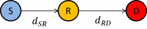
Let us consider a simple cooperative network composed of one Source (S), one Relay (R) and one Destination (D), as shown in Figure 1.
Figure 1. S-R-D network
The channels S-R and R-D are assumed to be block-fading channels impaired by Gaussian noise of variance $N_{0}$. For simplicity, all transmitting nodes are assumed to use the same energy per symbol, $E_{s}$, the same channel code and the same modulation scheme. Let $d_{X Y}$ denote the distance between nodes $\mathrm{X}$ and $\mathrm{Y}$. The path-loss factor between nodes $\mathrm{X}$ and $\mathrm{Y}$ is $l\left(d_{X Y}\right)=d_{X Y}^{-\alpha}$, where $\alpha$ is the path-loss exponent. As a result, the channel X-Y in time-slot $t$ is modeled as [12]:
$\boldsymbol{y}_{X Y . t}=\sqrt{E_{S} l\left(d_{X Y}\right)} \boldsymbol{h}_{X Y . t} \odot \boldsymbol{x}_{t}+\boldsymbol{w}_{X Y . t}$ (1)
where, $\sqrt{E_{s}} \boldsymbol{x}_{t}$ is the vector of modulated symbols with average energy $E_{s} ; \boldsymbol{w}_{X Y, t} \sim C N\left(0, N_{0}\right)$ is the vector of white complex noise; $\boldsymbol{h}_{X Y, t} \sim C N(0,1)$ is the vector of Rayleigh fading coefficients with parameter $\sigma_{h}=\sqrt{2} / 2$; and where $\odot$ represents the element-wise multiplication of the two vectors. Note that since Relay working on DMF mode performs only hard demodulation (without checking the integrity of the received signal), then for the channel R-D the transmitted symbols are only the estimated versions of the original symbols transmitted by the Source, $\tilde{\boldsymbol{x}}_{t}$.
For the issue of determining the optimal fixed position of the Relay, in the following subsections we will provide theoretical and numerical analysis for the entire link S-R-D.
3.1 Exact symbol error demodulation rate for the link S-R-D
The transmitted signals on both channels, S-R and R-D, are usually impaired by various physical phenomena, like path-loss, shadowing, fading, interference, etc., thus resulting in demodulation errors at the receiver side at both, the Relay and the Destination. Therefore, the rate of symbol demodulation errors for the whole channel S-R-D needs to count for both hops, S-R and R-D. Denoting with $\tau_{X Y}$ the probability of symbol error after demodulation on the channel X-Y, then the probability of symbol error after demodulation on the two-hop link S-R-D is given [2]:
$\tau_{S R D}=\left(1-\tau_{S R}\right) \cdot \tau_{R D}+\left(1-\tau_{R D}\right) \cdot \tau_{S R}$ (2)
Probability that a symbol is demodulated in error on the channel X-Y with fading coefficients $h_{X Y}$ and when BPSK modulation is used, is given with [11]:
$\tau_{X Y}(\Gamma)=Q(\sqrt{2 \Gamma})$ (3)
where, $Q(\cdot)$ is the $\mathrm{Q}$ function, and $\Gamma$ is the instantaneous SNR and it is given with $\Gamma=\frac{E_{s} \cdot l\left(d_{X Y}\right)}{N_{0}}\left|h_{X Y}\right|^{2}$.
Channel coefficients $\left|h_{X Y}\right|$ follow Rayleigh distribution, while $\left|h_{X Y}\right|^{2}$ follow chi-square distribution with two degrees of freedom. Then, the probability density function $f(\Gamma)$ is given with [12]:
$f(\Gamma)=\frac{1}{\bar{\Gamma}} e^{-\frac{\Gamma}{\bar{\Gamma}}}$ (4)
where, $\bar{\Gamma}$ is the average receive SNR on the channel X-Y and it is given as:
$\bar{\Gamma}=\frac{E_{S} \cdot l\left(d_{X Y}\right)}{N_{0}} \mathbf{E}\left[\left|h_{X Y}\right|^{2}\right]=\frac{E_{S} \cdot l\left(d_{X Y}\right)}{N_{0}}$ (5)
since the variance is $\mathbf{E}\left[\left|h_{X Y}\right|^{2}\right]=1$.
Now, averaging over all possible instantaneous SNRs, Γ, we obtain the average symbol error rate after BPSK demodulation on the Rayleigh fading channel X-Y as [13]:
$\tau_{X Y}=\int_{0}^{\infty} \tau_{X Y}(\Gamma) \cdot f(\Gamma) d \Gamma=\frac{1}{2}\left(1-\sqrt{\frac{\bar{\Gamma}}{1+\bar{\Gamma}}}\right)$ (6)
By using the Eqns. (2) and (6), for any given setup, we expect intuitively that the curve of $\tau_{S R D}$ to be with even symmetry toward the Relay location $d_{S R} / d_{S D}=0.5$, which corresponds with the middle of distance S-D. But, one open question that we want to answer is which is the optimal position of the Relay if we use channel coding. Therefore, since the channel decoding requires the evaluation of Log-Likelihood ratio (LLR) of the received symbols over the link S-R-D, then in the following subsection we will address the theoretical approach of the LLR evaluation.
3.2 Exact Log-Likelihood Ratio of the S-R-D received symbols
At the Destination, we can observe the symbol realizations on the channel R-D, $y_{R D}$, and also we assume that the Destination knows the statistics of the channel S-R (i.e. the probability of symbol error after demodulation, $\tau_{S R}$). Both these two quantities help us to evaluate the likelihood functions at the Destination, which for our case of DMF Relay needs to be marginalized over the cases when Relay may forward the correctly demodulated symbols from the Source, or it may forward the erroneously demodulated symbols from the Source [14]:
$p\left(y_{S R D} \mid x=x_{S}\right)=p\left(y_{R D} \mid x=x_{S}\right) \cdot\left(1-\tau_{S R}\right)+p\left(y_{R D} \mid x=\overline{x_{s}}\right) \cdot \tau_{S R}$ (7)
where, symbol $x_{s} \in\{0,1\}$ and the $\overline{x_{s}}$ represents the complementary symbol of $x_{s}$, and $p\left(y_{R D} \mid x\right)$ is given as:
$p\left(y_{R D} \mid x\right)=\frac{1}{\pi N_{0}} e^{-\frac{\left|y_{R D}\quad-\sqrt{E_{s\quad} l\left(d_{R D\quad}\right)} \boldsymbol{\quad h}_{R D \quad}x\right|^{2}}{N_{0}}}$ (8)
Then, the Destination demodulator calculates the Log-Likelihood Ratio (LLR) for each received symbol as:
$\Lambda=L L R(x)=\log \frac{p\left(y_{R D\quad} \mid x=x_{0}\right)}{p\left(y_{R D\quad} \mid x=x_{1}\right)}$ (9)
where, $x_{0}$ is associated to the case when $x_{s}=$ "0" and $x_{1}$ is associated to the case when $x_{s}=$ "1". Substituting the combination of Eqns. (1), (7) and (8) into (9), the symbol LLR can be evaluated as:
$\begin{aligned} \Lambda_{S R D} &=\log \left\{e^{-Y_{0, R D}}-\tau_{S R}\left[Y_{0, R D}-Y_{1, R D}\right]\right\}-\log \left\{e^{-Y_{1, R D}}+\tau_{S R}\left[Y_{0, R D}-Y_{1, R D}\right]\right\} \end{aligned}$ (10)
where,
$Y_{0, R D}=\frac{\left|\left(x-x_{0}\right) h_{R D} \sqrt{E_{s} \cdot l\left(d_{R D}\right)}+w_{R D\quad}\right|^{\quad 2}}{N_{0}}$ (11)
$Y_{1, R D}=\frac{\left|\left(x-x_{1}\right) h_{R D} \sqrt{E_{s} \cdot l\left(d_{R D}\right)}+w_{R D\quad}\right|^{\quad 2}}{N_{0}}$ (12)
Since the matter of interest is the average value of LLR, denoted by $\bar{\Lambda}_{S R D}$, it's value can be evaluated by averaging the Eq. (10) over the various realizations of random variables $x, h_{R D}$ and $w_{R D}$, given with respective probability density functions (pdf) as below:
$f_{x}\left(x_{s}\right)=\frac{1}{2} \delta\left(x_{s}+1\right)+\frac{1}{2} \delta\left(x_{s}-1\right)$ (13)
$f_{h_{R D}}\left(h ; \sigma_{h}\right)=\frac{h}{\sigma_{h}^{2}} e^{-\frac{h^{2}}{2 \sigma_{h}^{2}}} \quad; h \in(-\infty, \infty)$ (14)
$f_{w_{R D}}(w)=\frac{1}{\sigma_{w} \sqrt{2 \pi}} e^{-\frac{|w|^{2}}{2 \sigma_{w}^{2}}}\quad ; w \in(-\infty, \infty)$ (15)
which yields the following form for $\bar{\Lambda}_{S R D}$ :
$\bar{\Lambda}_{S R D}=\mathrm{E}\left[\Lambda_{S R D}\right]=\iiint \Lambda_{S R D}\left(x, h_{R D}, w_{R D}\right) \cdot f_{x}\left(x_{s}\right) f_{h_{R D}}\left(h ; \sigma_{h}\right) f_{w_{R D}}(w) d x d h_{R D} d w_{R D}$ (16)
Note that for the direct link, S-D, the $\bar{\Lambda}_{S D}$ can be evaluated in analogy with the Eq. (16), with the $\Lambda_{S D}$ taking a simpler form:
$\Lambda_{S D}=\frac{1}{N_{0}}\left\{\left|\left(x-x_{1}\right) \cdot h_{S D}+w_{S D}\right|^{2}-\mid\left(x-x_{0}\right)\right.\cdot\left.h_{S D}+\left.w_{S D}\right|^{2}\right\}$ (17)
3.3 Criterion for determining the optimal position of the Relay
It is known that the sign of an LLR value denotes the detected bit result and its absolute value denotes the degree of confidence [15]. Therefore, a higher absolute value of LLR represents a higher confidence that the decoding decision would be correct. The average of absolute value of LLR can be evaluated as:
$\left|\bar{\Lambda}_{S R D}\right|=\frac{\sum_{i=1\quad}^{n_{c}}\left|\Lambda_{i}\right|}{n_{c}}$ (18)
where, $\left|\Lambda_{i}\right|$ represents the average absolute value of LLR of the i-th coded bit, and $n_{c}$ represents the number of coded bits. Note that the measure $\left|\bar{\Lambda}_{S R D}\right|$ is evaluated before the Destination performs channel decoding, and hence it represents a measure of the confidence on the coded bits.
So, we have two metrics that we use to measure the quality of the link S-R-D, $\tau_{S R D}$ and $\left|\bar{\Lambda}_{S R D}\right|$. But, as we will see later, we cannot rely solely on neither metric, as the optimal position of the Relay according to the lowest value of $\tau_{S R D}$ does not corresponds to the optimal position of the Relay according to the highest value of $\left|\bar{\Lambda}_{S R D}\right|$. Therefore, we propose a trade-off metric or criterion that take into account both measures, $\tau_{S R D}$ and $\left|\bar{\Lambda}_{S R D}\right|$. Researching into this direction, we have observed that the ratio between the two, $\left|\bar{\Lambda}_{S R D}\right|$ and $\tau_{S R D}$, which we call as ratio of confidence $\rho_{c}$, tells us the best compromise between the two measures and hence the optimal position of the Relay. Defining this ratio as a metric, then the criterion for choosing the optimal position of the Relay would be the one which produces the highest value of the ratio $\rho_{c}$, as:
$\max _{d_{S R} / d_{S D\quad}} \rho_{C}=\max _{d_{S R} / d_{S D}} \frac{\left|\bar{\Lambda}_{S R D\quad}\right|}{\tau_{S R D}}$ (19)
We consider that as high as the ratio $\rho_{c}$ is, we have higher confidence that the errors could be corrected in the decoder.
In this section we want to check numerically whether our theoretical approaches match with the numerical results, and whether the optimal position of the Relay predicted with our proposed criterion matches with the numerical results regarding the optimal position of the Relay after decoding at the Destination. Moreover, in the end, we will also check how our criterion stands compared to other proposed criterions from literature. In the following we consider Convolutional Coding with code rate $R_{c}=1 / 3$ and BPSK modulation. A numerical extension for 16-QAM complex modulation will be provided as well. The information Packet Data Unit (PDU) is 1000 bits long. The average energy per modulated symbol is $E_{s}=1$, and the path-loss exponent is $\alpha=2.4$. The transmit $E_{b} / N_{0}$ is the same on the channels S-D and R-D.
4.1 Theoretical accuracy versus numerical simulations
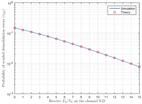
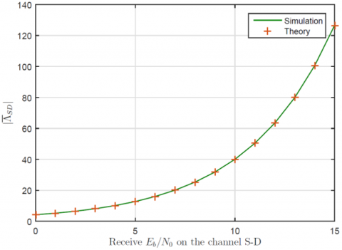
In Figure 2 there is shown the probability of symbol demodulation error, $\tau_{S D}$ as a function of receive $E_{b} / N_{0}$ on the channel S-D, where we see that the theoretical approach matches perfectly with the numerical results using Monte Carlo simulation, while in Figure 3 there is shown the absolute value of LLR on the channel S-D, $\left|\bar{\Lambda}_{S R D}\right|$, where we see that the theoretical approach matches perfectly with the numerical results using simulation.
Figure 2. Probability of symbol demodulation error on the channel S-D
Figure 3. Average absolute value of LLR on the channel S-D
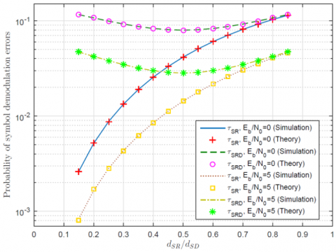
On the case when a Relay is used to assist the communication between the Source and the Destination, then it is important to find on which location there is achieved the lowest rate of symbol demodulation errors for the whole path S-R-D. Note that the Relay works in DMF mode, which means that depending on the channel S-R, sometimes the Relay may demodulate erroneously the received symbols from the Source and thus forward the wrong symbols toward the Destination. In Figure 4 there are shown the probability of demodulation errors on the channel S-R and for the entire link S-R-D, for various position of the Relay. As expected, we see that as Relay moves closer to the Source, it experiences lower rate of demodulation errors $\tau_{S R}$ and this rate increases as Relay moves further toward the Destination. But, we see that the overall rate of symbol demodulation errors for the entire link S-R-D achieves the lowest value when Relay is located in the middle of distance S-D, $d_{S R} / d_{S D}=0.50$. As it may be seen, putting the Relay at this distance, balances the demodulation errors on both hops, S-R and R-D, which implies $\tau_{S R}=\tau_{R D}$. Moreover, repeating the experiment for two different values of $E_{b} / N_{0}$, we see that the theoretical analysis matches perfectly with the numerical analysis.
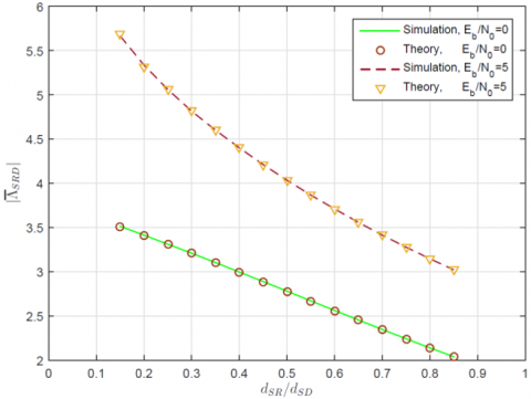
In Figure 5 there is shown the average absolute value of LLR for the entire link S-R-D, as a function of various position of the Relay. We see that the highest value of $\left|\bar{\Lambda}_{S R D}\right|$ it is achieved when the Relay appears close to the Source, which corresponds to the highest degree of confidence, and we see that the value of $\left|\bar{\Lambda}_{S R D}\right|$ decreases as the Relay moves toward the Destination. This is something we may justify with the fact that when closer to the Source, Relay experiences very few errors, and when closer to the Destination, Relay demodulates most of the received symbols in errors, and therefore even though the distance R-D is short, the Destination cannot recover the forwarded errors encountered on the channel S-R. Moreover, we see that the theoretical analysis approach developed in Section 3.2, matches perfectly with the simulation results.
Figure 4. Probability of symbol demodulation errors, various $d_{S R} / d_{S D}$
Figure 5. Average absolute value of LLR on the channel S-R-D, various $d_{S R} / d_{S D}$
4.2 Prediction of the optimal fixed position of the Relay
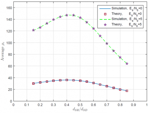
As we may see from Figure 4 and Figure 5 , the Relay location at which $\tau_{S R D}$ achieves its best value, does not match with the relay location where $\left|\bar{\Lambda}_{S R D}\right|$ achieves its best value. That is why we propose this new criterion $\rho_{c}$, which brings the best of two metrics. In Figure 6 it is shown the value of proposed criterion $\rho_{c}$ as a function of various position of the Relay $d_{S R} / d_{S D}$ and for two different points of $E_{b} / N_{0}$. We can observe that the highest value of $\rho_{c}$, and hence the optimal position of the Relay, it is achieved when the Relay is located around the distance $d_{S R} / d_{S D}=0.35$, which corresponds to the 1/3 of the distance S-D.
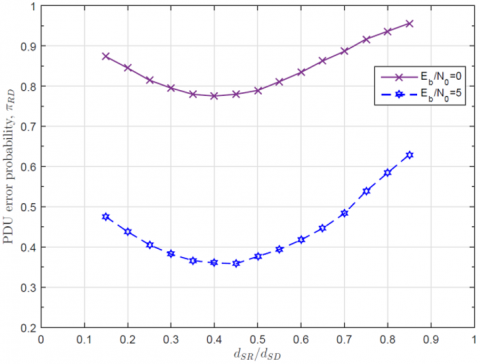
Now, let us take a look what results do we get after the Destination decodes the received PDU. In Figure 7 there is shown the probability that a single PDU transmitted from the Relay is received with error after decoding at the Destination, $\pi_{R D}$, for various position of the Relay, where we see that the optimal position of the Relay appears around the location $d_{S R} / d_{S D}=0.35$, where there is experienced the lowest probability of error. This result is very closely matched with the prediction via our proposed criterion as shown in Figure 6.
Figure 6. Average value of criterion $\rho_{c}$ on the channel S-R-D, various $d_{S R} / d_{S D}$
Figure 7. PDU error probability on the channel R-D, $\pi_{R D}$, various $d_{S R} / d_{S D}$
4.3 Extension to a higher order modulation
In order to check that our analysis holds not only for the BPSK modulation but that it could be extended to higher order modulations, in the following we will provide numerical results for 16-QAM modulation.
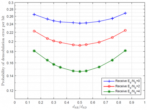
In Figure 8, there is shown the probability of bit error on the channel S-R-D, after symbol demodulation at the Destination, for various position of the Relay, $d_{S R} / d_{S D}$. Note that when we use rectangular constellation based on Gray coding, in MQAM modulation, we may assume that the bit error probability $\emptyset_{S R D}$ is $k$-times smaller than the symbol error probability $\tau_{S R D}[16]$, where $k=\log _{2}(M)$ is the number of bits per M-QAM symbol. As expected, the lowest rate of demodulation errors appears in the middle of the distance S-D, $d_{S R} / d_{S D}=0.50$. In order to avoid any confusion, please note that at the shown results using M-QAM modulation, $E_{b} / N_{0}$ denotes the ratio per information bit and not the ratio for coded bit!
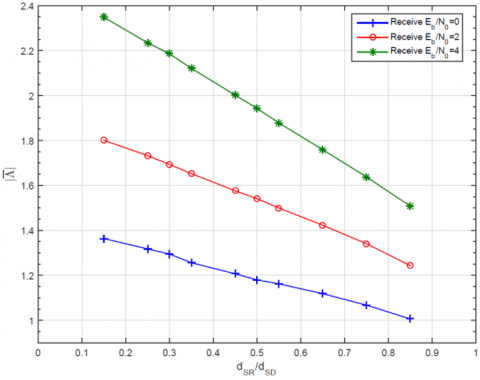
According to the Eq. (18), the value of $\left|\bar{\Lambda}_{S R D}\right|$ for various location of the Relay and for $E_{b} / N_{0} \in\{0,2,4\}$ is shown in Figure 9 , where we may see that we experience the same behaviour as with the BPSK modulation: the value of $\left|\bar{\Lambda}_{S R D}\right|$ is higher when the Relay is located close to the Source and it decreases as the Relay moves further toward the Destination.
Figure 8. Bit error probability after symbol demodulation on the channel S-R-D, various $d_{S R} / d_{S D}$
Figure 9. Average absolute value of the LLR per coded bit at the Destination, various $d_{S R} / d_{S D}$
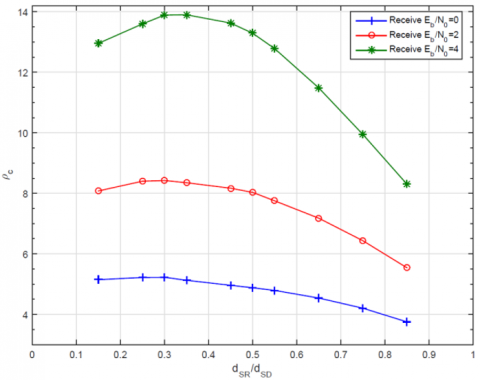
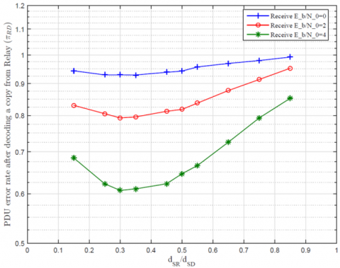
The metric (19) for the existing setup of 16-QAM modulation, is shown in Figure 10, where we see that the best (highest) value according to our criterion shown in Figure 10, corresponds very closely with the lowest probability of PDU error as seen in Figure 11.
The optimal position appears to be around the location $d_{S R} / d_{S D}=0.35$, where we apparently have the best trade-off between the demodulation errors on the channel S-R and the delivery success on the remaining channel R-D.
Figure 10. Values of proposed criterion for various $d_{S R} / d_{S D}$
Figure 11. PDU error probability on the channel R-D, $\pi_{R D}$, various $d_{S R} / d_{S D}$
Note that the above results using M-QAM modulation are achieved using Monte Carlo simulations, while the theoretical approach can be extended in analogy with the analysis developed in Section 3. Anyway, the numerical analysis and simulation shown for these two different modulation schemes, are sufficiently to conclude that the optimal fixed position of the DMF Relay appears around the location 1/3 of the distance S-D. Our concluded result for the optimal Relay position seems to correspond also with literature [17], but the study [17] do not provide any theoretical analysis or criterion on why it appears in this particular location.
4.4 Selection of the best instantaneous relay: comparison with a referent criterion
Let us consider a scenario where we have multiple Relays and we have to choose only one of them. Since for this problem various criterions have been proposed in literature, we want to choose one of these criterions and to compare it with our proposed criterion. On [18] there is proposed a criterion based on the average absolute value of Log Likelihood Ratio (LLR), $|\bar{\Lambda}|$, where the best Relay it is chosen the one which has the highest $|\bar{\Lambda}|$ among the candidate Relays, and then this value it is compared with the value $|\bar{\Lambda}|$ of the channel S-D. Since when Relay is located close to the Source it has most of the time $\left|\bar{\Lambda}_{S R}\right|>\left|\bar{\Lambda}_{S D}\right|$, then we assume that the condition for activating a Relay in Ref. [18] is fulfilled most of the time. Moreover, Aexan and El Mahdy [18] consider a random distribution of Relays, but in our case we want to perform the comparison of our criterion with the referent criterion on the link S-R targeting the Relays distributed around the optimal location obtained in previous subsection.
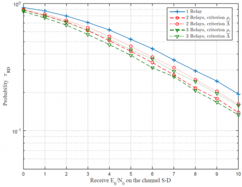
Comparison of the two criterions is shown in Figure 12, where it is shown the probability of PDU error, $\pi_{R D}$, as a function of receive $E_{b} / N_{0}$ per information bit on the channel S-D, 16-QAM modulation, for the following cases: when we have only 1 Relay appearing at that particular location, when we have 2 Relays (only one is chosen) at that location, and when we have 3 Relays (only one is chosen) at that location. As we may see from the comparison, on each case, we see that the performance achieved with our criterion $\rho_{c}$ is better than with the referent criterion $|\bar{\Lambda}|$.
Figure 12. Comparison of $\pi_{R D}$ achieved with both criterions
In this paper we have addressed the issue of determining the optimal position of the Relay and the single Relay selection among a set of candidate Relays to be chosen for relaying the information between a Source and a Destination. Considering the Relay on DMF mode due to its simple nature in implementation and high potential to be used for IoT-based technologies, we have proposed a criterion for Relay selection which is based on two important measures, the absolute value of LLR and the probability of demodulation errors. Our analysis shows that our criterion predicts very closely the optimal position of the Relay, where the theoretical results matches perfectly with the simulation results. Comparison of our proposed criterion with a referent criterion from literature shows that our criterion performs better in terms of selecting the best Relay to cooperate.
|
$N_{0}$ |
gaussian noise variance |
|
$E_{S}$ |
average energy per constellation symbol |
|
$\alpha$ |
path-loss exponent |
|
$l(\cdot)$ |
path-loss factor |
|
$t$ |
time-slot |
|
$\boldsymbol{y}_{X Y, t}$ |
vector of the received symbols on time slot t, on the channel X-Y |
|
$\boldsymbol{h}_{X Y, t}$ |
vector of the Rayleigh coefficients on time slot t, on the channel X-Y |
|
$\boldsymbol{w}_{X Y, t}$ |
vector of the white Gaussian noise over the channel X-Y, at time slot t |
|
$\boldsymbol{x}_{t}$ |
vector of transmitted symbols on time-slot t |
|
$\tilde{\boldsymbol{x}}_{t}$ |
vector of demodulated symbols on time-slot t |
|
$C N(\cdot)$ |
complex normal distribution |
|
$\sigma_{h}$ |
scale parameter at Rayleigh distribution |
|
$\tau_{X Y}$ |
probability of symbol error after demodulation on the channel X-Y |
|
$\Gamma$ |
instantaneous signal-to-noise (SNR) ratio |
|
$\bar{\Gamma}$ |
average receive SNR |
|
$Q(\cdot)$ |
Q function |
|
$f(\cdot)$ |
probability density function |
|
$p\left(y_{X Y} \mid x\right)$ |
likelihood function of received channel realization $y_{X Y}$ when symbol x is transmitted |
|
$\Lambda_{X Y}$ |
instantaneous log-likelihood ratio per symbol, realized on the channel X-Y |
|
$\bar{\Lambda}_{X Y}$ |
average log-likelihood ratio per symbol, realized on the channel X-Y |
|
$n_{c}$ |
number of coded bits on the received sequence |
|
$\rho_{c}$ |
ratio of confidence |
|
$R_{c}$ |
channel code rate |
|
$E_{b} / N_{0}$ |
ratio of receive energy to noise per bit on the channel S-D |
|
$\emptyset_{X Y}$ |
bit error probability after demodulation on the channel X-Y |
[1] Nosratinia, A., Hunter, T.E., Hedayat, A. (2004). Cooperative communication in wireless networks. IEEE Communications Magazine, 42(10): 74-80. https://doi.org/10.1109/MCOM.2004.1341264
[2] Wang, T., Cano, A., Giannakis, G.B., Laneman, J.N. (2007). High-performance cooperative demodulation with decode-and-forward relays. IEEE Transactions on Communications, 55(7): 1427-1438. https://doi.org/10.1109/TCOMM.2007.900631
[3] Falavarjani, M.F., Hoshyar, R., Tafazolli, R. (2010). Performance evaluation of a flexible amplify and forward (AF) combined with HARQ. 21st Annual IEEE International Symposium on Personal, Indoor and Mobile Radio Communications, Istanbul, Turkey, pp. 488-493. https://doi.org/10.1109/PIMRC.2010.5671902
[4] Chen, D., Laneman, J.N. (2006). Modulation and demodulation for cooperative diversity in wireless systems. IEEE Transactions on Wireless Communications, 5(7): 1785-1794. https://doi.org/10.1109/TWC.2006.1673090
[5] Uyoata, U., Mwangama, J., Adeogun, R. (2021). Relaying in the Internet of Things (IoT): A Survey. IEEE Access, 9: 132675-132704. https://doi.org/10.1109/ACCESS.2021.3112940
[6] Bulakci, O. (2012). Multi-hop moving relays for IMT-advanced and beyond. arXiv preprint arXiv:1202.0207.
[7] Aggarwal, V., Bennatan, A., Calderbank, A.R. (2009). On maximizing coverage in gaussian relay channels. IEEE Transactions on Information Theory, 55(6): 2518-2536. http://dx.doi.org/10.1109/TIT.2009.2018337
[8] Mohammed, H., Khalaf, T.A. (2013). Optimal positioning of relay node in wireless cooperative communication networks. 2013 9th International Computer Engineering Conference (ICENCO), Giza, Egypt, pp. 122-127. https://doi.org/10.1109/ICENCO.2013.6736487
[9] Li, S., Yang, K., Zhou, M., Wu, J., Song, L., Li, Y., Li, H. (2017). Full-duplex amplify-and-forward relaying: Power and location optimization. IEEE Transactions on Vehicular Technology, 66(9): 8458-8468. https://doi.org/10.1109/TVT.2017.2686872
[10] Liu, Y., Sung, C.W. (2013). Network-coded retransmissions in wireless demodulate-and-forward relay channels. EURASIP Journal on Wireless Communications and Networking, 2013(1): 136. https://doi.org/10.1186/1687-1499-2013-136
[11] Alouane, W.H., Hamdi, N., Meherzi, S. (2012). Accurate BEP of adaptive demodulate-and-forward relaying over Rayleigh fading channels. 2012 IEEE Symposium on Computers and Communications (ISCC), Cappadocia, Turkey, pp. 000129-000131. https://doi.org/10.1109/ISCC.2012.6249280
[12] Maliqi, F., Bassi, F., Duhamel, P., Limani, I. (2019). A probabilistic HARQ protocol for demodulate-and-forward relaying networks. IEEE Transactions on Wireless Communications, 18(3): 1623-1636. https://doi.org/10.1109/TWC.2019.2894642
[13] Rao, K.D. (2015). Channel Coding Techniques for Wireless Communications. Springer India, 1-20.
[14] Maliqi, F. (2017). On the interaction of cooperation techniques with channel coding and ARQ in wireless communications. Doctoral dissertation. Université Paris-Saclay; Universiteti i Prishtinës.
[15] Sklar, B. (2001). Digital Communications: Fundamentals and Applications. Prentice-Hall, Upper Saddle River.
[16] Pahlavan, K., Levesque, A.H. (2005). Wireless Information Networks (Vol. 93). John Wiley & Sons.
[17] Vu, X.T., Di Renzo, M., Duhamel, P. (2013). Multiple-access relaying with network coding: Iterative network/channel decoding with imperfect CSI. EURASIP Journal on Advances in Signal Processing, 2013(1): 170. https://doi.org/10.1186/1687-6180-2013-170
[18] Alexan, W., El Mahdy, A. (2014). Relay selection based on the log likelihood ratio for cooperative communication networks. 2014 Signal Processing: Algorithms, Architectures, Arrangements, and Applications (SPA), Poznan, Poland, pp. 149-153.