Duc Ngoc Nguyen | Tuan Anh Nguyen* | Thang Binh Hoang | Ngoc Duyen Dang
© 2021 IIETA. This article is published by IIETA and is licensed under the CC BY 4.0 license (http://creativecommons.org/licenses/by/4.0/).
OPEN ACCESS
The roll angle of the vehicle $\varphi$ is a characteristic parameter for the vehicle's instability. This value appears when the vehicle steers. If the vehicle’s body is tilted, the value of the vertical force at the wheels Fzij will also change. When the value of Fzij reaches zero, the wheel will be lifted off the road, the rollover phenomenon can occur. At this time, the roll angle of the vehicle will reach the maximum value $\varphi_{\max }$. Previous researches have often used only the vehicle dynamics model to determine the limits of this phenomenon. However, the calculation and simulation process are quite complicated. Therefore, this research has proposed a novel method that can calculate the limit of the rollover phenomenon more easily. In this research, the Rollover State Function (RSF) was established to calculate the limited roll angle of the vehicle. According to the content of the paper, this function depends only on the basic dimensions of the vehicle such as the height of center of the gravity, the track width, etc. Besides, it has relatively high accuracy, even when the vehicle's mass changes, its difference is not large. Therefore, the results of the paper can be applied to later studies to predict the rollover phenomenon.
dynamic vehicle, rollover state function (RSF), roll angle, limit of rollover
When the vehicle moves on the road, many factors affect the stability and safety of the vehicle. These problems can cause unsafety for passengers and cargo. In particular, the phenomenon of the lateral instability of the vehicle is one of the very dangerous phenomena [1]. This phenomenon can even lead to rollover [2]. Therefore, the reduction of the rollover phenomenon of the vehicle when steering is always focused on research and improvement by manufacturers.
When the vehicle steers, the centrifugal force will appear. This force causes the vehicle body is tilted. Consequently, the vertical forces at the wheels Fzij will also change. If the roll angle of the vehicle body $\varphi$ is greater, the change of Fzij will also increase. When this value reaches zero, the wheel will be lifted off the road surface [3]. At this time, lateral instability can occur. Especially, the vehicle can rollover in a very small time, the roll angle of the vehicle will be the max value $\varphi_{\mathrm{max}}$.
The rollover phenomenon is very dangerous and complicated, it depends on many reasons. According to [4, 5], the size of the vehicle affects this problem. Besides, motion conditions also greatly affect the vehicle's rollover limit [6]. To improve this phenomenon, the time when the vehicle rollovers need to be predicted in advance. However, calculating this limit is very difficult. In [7], Chu et al predicted the rollover speed on curves for the heavy vehicle by the dynamics model describing the vehicle's limited speed. Gonzalez et al have simultaneously estimated both the rollover and the sideslip of the wheel through the use of artificial intelligence (deep learning method) [8]. This issue is also studied by Nam et al for electric vehicle models [9]. Besides, Syed and Vigliani also introduced the model that is used to predict both of these parameters in their paper [10]. The dependence between the vehicle's roll angle and the vehicle's speed was shown in Zhao and Liu's study [11]. Anh and Binh have shown that the vehicle's limit of the rollover is a function depending on the velocity and the height of the center of gravity [12]. In Ref. [13], Blume et al. designed the neural control system to predict the roll angle of the vehicle body when moving. Previously, Tseng et al. used inertial measurement units (IMU) to predict the roll angle and pitch angle of the vehicle, this method is unique [14]. Similarly, a method of using a cost-effective six-dimensional inertial measurement unit used to estimate roll and pitch angles were also proposed by Oh and Choi [15]. Hyun and Langari also introduced a rollover prediction model for tractor-semitrailers [16]. According to the Ref. [17], to control modern systems that improving vehicle's stability and safety when moving on the road, these mechatronic systems need to be programmed with complex algorithms. Besides the development of IoT technology (Internet of Things), Garcia Guzman et al. have introduced a method to predict the roll angle of the vehicle based on the neural network of IoT devices. Especially, its cost is quite cheap [18]. Most recently, Zhu et al. have developed the rollover prediction method for the truck based on an experimental model with many observed variables [19]. Besides, many models predicting the limit of rollover and the rollover index were also performed [20-29].
The aforementioned methods and models all bring positive effects to the calculation and prediction of the vehicle's the limit of rollover when moving. However, the models that are used in those papers are quite complex. For the most part, they require complex dynamics modeling to simulate the vehicle's oscillation. This research focuses on establishing the rollover state function (RSF) to predict the limited roll angle of the vehicle.
When the vehicle steers, under the effect of the centrifugal force, the vehicle body will be tilted. At this time, the vertical forces on the two wheels of each axle Fzij will change.
$F_{z i j}=F_{g i j}+F_{K T i j}$ (1)
The weight applied to each wheel depends on the roll angle of the vehicle. If the roll angle is greater, this difference is much.
$F_{g i j}=\frac{\left\{M_{i}\left[t_{w i} \pm h \sin \varphi\right]+2 t_{w i} m_{i j}\right\} g}{2 t_{w i}}$ (2)
The elastic force of the tire is proportional to the displacement of the unsprung mass $\xi_{\mathrm{ij}}$ and the stimulation from the road surface uij.
$F_{K T i j}=K_{T i j}\left(u_{i j}-\xi_{i j}\right)$ (3)
When the vertical force at the wheel Fzij reaches zero, the vehicle will experience lateral instability. In particular, this situation can cause the vehicle to rollover. To improve vehicle’s safety, this situation needs to be anticipated.
As the vehicle moves, the value of the vertical force at the wheels Fzij can change continuously. Determining this exact value is not simple. Eq. (4) shows the change of Fzij when the vehicle body is tilted. To compute the value of Fzij in this way, a complex dynamic model needs to be established.
$F_{z i j}=\frac{\left\{M_{i}\left[t_{w i} \pm h \sin \varphi\right]+2 t_{w i} m_{i j}\right\} g}{2 t_{w i}}+K_{T i j}\left(u_{i j}-\xi_{i j}\right)$ (4)
The vehicle has lateral instability when Fzij = 0, that is:
$\varphi_{\max }=\arcsin \left\{\frac{t_{w i}}{h}\left[\frac{2}{M_{i}}\left(m_{i j}-\frac{K_{T i j} \xi_{i j m a x}}{g}\right)+1\right]\right\}$ (5)
If the values of the dimensions of the vehicle are constant, the maximum value of the limited roll angle only depends on the value of the maximum displacement of the unsprung mass $\xi_{\text {ijmax }}$. According to Anh [30], the value of the maximum displacement of the unsprung mass $\xi_{\text {ijmax }}$ can be determined relatively accurately in the following way:
$\xi_{i j m a x}=\frac{F_{z i j 0}}{\alpha \gamma}$ (6)
Hence, Eq. (5) can be rewritten to:
$\begin{aligned}
&\varphi_{\max }= \\
&\arcsin \left\{\frac{t_{w i}}{h}\left[\frac{2}{M_{i}}\left(m_{i j}-\frac{K_{T}\left(\frac{M_{i}}{2}+m_{i j}\right)}{\alpha \gamma}\right)+1\right]\right\}
\end{aligned}$ (7)
Eq. (7) shows the relationship between the maximum limited roll angle $\varphi_{\max }$ and dimensional parameters. When these values are known in advance, the maximum limited roll angle $\varphi_{\max }$ can easily be determined without using complex dynamic models.
After establishing the equations which describe the relationship between the limited roll angle $\varphi_{\max }$ and the vehicle's dimensions, the calculation is performed. The simulation process is done by Matlab-Simulink software. This is a very special mathematical tool, and it is suitable for simulation problems of vehicle dynamics.
Simulation is performed when the vehicle steers at a steady speed. The parameters of the reference vehicle are shown in Table 1. The sprung mass is varied between 1500 (kg) and 1900 (kg). Besides, the unsprung mass also varies, from 30 (kg) to 60 (kg). In addition, a number of other parameters about the vehicle's dimensions are also changed within the specified range.
Table 1. Parameter of the vehicle
|
Description |
Symbol |
Value |
Unit |
|
Sprung mass |
M |
1500 ~ 1900 |
kg |
|
Unsprung mass |
mij |
30 ~ 60 |
kg |
|
Height of the center of gravity |
h |
0.3 ~ 0.7 |
m |
|
Half of the track width |
twi |
0.7 ~ 0.8 |
m |
|
Stiffness of the tire |
KTij |
120000 |
N/m |
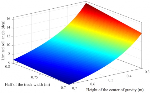
Figure 1. The limited roll angle (M = 1700 kg, mij = 45 kg)
The graph Figure 1 shows the dependence between the limited roll angle $\varphi_{\max }$ on the track width twi and the height of the center of gravity h in the case of the simulation. When the height of the center of gravity h increases, the value of the limited roll angle $\varphi_{\max }$ will decrease, which is completely suitable. As a result, vehicles having the height of the center of gravity are high will be instability. On the contrary, if the track width twi increases, the limited roll angle jmax tends to increase. In this case, the maximum and minimum values of the limited roll angle are 16.06° and 5.95° respectively. To improve the lateral instability of the vehicle when steering, the vehicle's dimensions need to be optimized.
When the sprung mass and unsprung mass of the vehicle change, the value of the limited roll angle will also change. Let Mx and mijx be the values of the sprung mass and the unsprung mass after being changed. Then, the difference between the value $\varphi_{\max }$ and $\varphi_{\mathrm{xmax}}$ can be determined as follows:
$\Delta \varphi=\left|\varphi_{\max }-\varphi_{x \max }\right|$ (8)
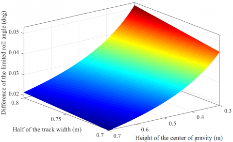
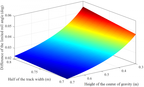
The graphs of Figure 2 and Figure 3 show the difference in the value of the limited roll angle $\Delta \varphi$ when the value of the sprung mass increases: Mx = 1750 (kg) and Mx = 1800 (kg). When this value increases, the limited roll angle $\varphi_{\mathrm{xmax}}$ will decrease, this change is very small. The value of the difference $\Delta \varphi$ corresponding to the above two cases is 0.052° and 0.100° respectively.
Figure 2. The limited roll angle (Mx = 1750 kg, mij = 45 kg)
Figure 3. The limited roll angle (Mx = 1800 kg, mij= 45 kg)
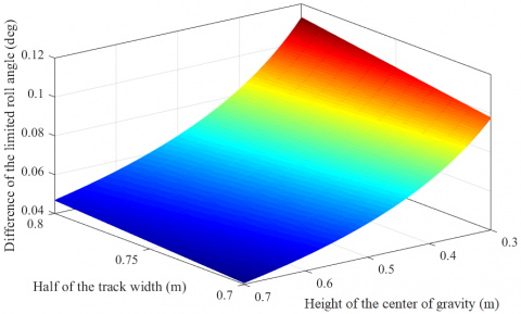
Otherwise, if the unsprung mass decrease, the value of the limited roll angle $\varphi_{\mathrm{xmax}}$ will increase proportionally. This change is indicated based on the graph of Figure 4 and Figure 5. The largest change is $\Delta \varphi$ = 0.055° and $\Delta \varphi$ = 0.113° respectively for the case Mx = 1650 (kg) and Mx = 1600 (kg). Overall, this difference is very small.
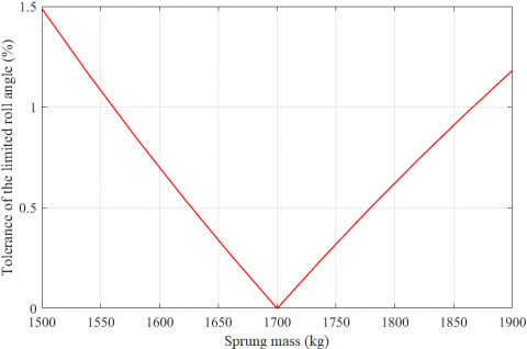
If the value of the sprung mass Mx continuously increases or decreases, the difference will change more. The graph of Figure 6 shows the tolerance for the value $\Delta \varphi$ if it is calculated by the function (7) when the value of the sprung mass Mx changes. If Mx = 1700 (kg) is selected as the fixed value, the difference of $\Delta \varphi$ will appear if Mx$\neq$M. This difference increases linearly as Mx changes. However, the value of the tolerance is quite small, it does not affect the result much, which is calculated by the established function.
Figure 4. The limited roll angle (Mx = 1650 kg, mij = 45 kg)
Figure 5. The limited roll angle (Mx = 1600 kg, mij = 45 kg)
Figure 6. The tolerance of the limited roll angle when the sprung mass changes
If the unsprung mass mijx changes, the limited roll angle $\varphi_{\max }$ will also change accordingly. The graph of Figure 7 has shown this. Similar to the above case, this change also increases linearly when the value of unsprung mass changes mij$\neq$mijx. This difference is quite small. Therefore, the established function can be used to determine relatively accurately the value of the limited roll angle $\varphi_{\max }$ based on the vehicle’s basic parameters.
Figure 7. The tolerance of the limited roll angle when the unsprung mass changes
When the vehicle steers at high speed, the body will be tilted under the influence of centrifugal force. The value of the roll angle will gradually increase if the steering angle continues to increase. If this value reaches the maximum limit, a rollover phenomenon can occur. This problem is very dangerous for the passengers and cargoes on the vehicle.
To be able to resolve this situation, the rollover phenomenon needs to be predicted in advance through the limited roll angle of the vehicle. Usually, the limited roll angle of the vehicle can be calculated by the model of spatial dynamics. However, if this model is used, the computation and simulation process are also very difficult and time-consuming. In order to make the calculation easier, this research presented the method of predicting the limited roll angle of the vehicle jmax based on the established state function. In this function, the value of the limited roll angle jmax only depends on the basic parameters of the vehicle.
The results of the calculation process by the state function have shown the dependence between the limited roll angle $\varphi_{\max }$ on the dimension and mass of the vehicle. When the height of the center of gravity h increases, the limited roll angle jmax will decrease rapidly. However, if the track width twi increases, the limited roll angle jmax can be increased accordingly. These changes are nonlinear. Besides, the sprung mass and unsprung mass also affect the value of the maximum limited roll angle. However, this change is small, it does not affect much on the prediction of the limited roll angle $\varphi_{\max }$ by the state function which has been established.
The results of the paper show the advantages of the state function that is used to predict the limited roll angle $\varphi_{\max }$. This function is only used to predict the limited roll angle when the wheel is lifted off the road surface. In the case of the vehicle normally move on the road, the calculation of the roll angle j cannot use this function. It is only suitable for calculating the maximum roll angle of the vehicle, which shows that the rollover phenomenon can occur. This state function applies to Sedan, SUV, CUV, Pick-up, etc., which are of equal dimension and mass. The tolerance of results when calculating is small, they do not affect the accuracy much.
The method used in this paper is completely novel and original. It supports the process of forecasting dangerous phenomena by being faster and simpler than other traditional methods. However, dynamic simulation solutions are needed to bring more accurate performance to the used model. In the future, more research predicting vehicle’s instability may be conducted based on this research.
|
Fg |
The weight applied to each wheel, N |
|
FKT |
The force of the tire, N |
|
Fz |
The vertical force at each wheel, N |
|
g |
Gravitational acceleration, m/s2 |
|
H |
Height of the center of gravity, m |
|
M |
Sprung mass, kg |
|
m |
Unsprung mass, kg |
|
tw |
Half of the track width, m |
|
Greek symbols |
|
|
a |
Constant |
|
$\gamma$ |
Constant |
|
$\varphi$ |
Roll Angle, rad |
|
$\xi$ |
Displacement of the unsprung mass, m |
[1] Chen, K., Pei, X., Ma, G., Guo, X. (2016). Longitudinal/lateral stability analysis of vehicle motion in the nonlinear region. Mathematical Problems in Engineering, 2016: 3419108. https://doi.org/10.1155/2016/3419108
[2] Nguyen, T.A., Hoang, T.B. (2019). Research on dynamic vehicle model equipped active stabilizer bar. Advances in Science, Technology, and Engineering Systems Journal, 4(4): 271-275. https://doi.org/10.25046/aj040434
[3] Tuan, A.N., Thang, B.H. (2020). Determining the vertical force when steering. Advances in Systems Science and Applications, 20(4): 27-35. https://doi.org/10.25728/assa.2020.20.4.870
[4] Cruz, P., Echaveguren, T., González, P. (2017). Estimation of heavy vehicle rollover potential using reliability principles. Revista Ingeniería de Construcción, 32(1): 5-14.
[5] Rajamani, R., Piyabongkarn D., Tsourapas V, Lew J.Y. (2011). Parameter and state estimation in vehicle roll dynamics. IEEE Transactions on Intelligent Transportation System, 12(4): 1558-1567. https://doi.org/10.1109/TITS.2011.2164246
[6] Li, B., Bei, S. (2019). Research method of vehicle rollover mechanism under critical instability condition. Advances in Mechanical Engineering, 11(1): 1-11. https://doi.org/10.1177/1687814018821218
[7] Chu, D., Li, Z., Wang, J., Wu, C., Hu, Z. (2018). Rollover speed prediction on curves for heavy vehicles using mobile smartphone. Measurement, 130: 404-411. https://doi.org/10.1016/j.measurement.2018.07.054
[8] González, L.P., Sánchez, S.S., Garcia-Guzman, J., Boada, M.J.L., Boada, B.L. (2020). Simultaneous estimation of vehicle roll and sideslip angles through a deep learning approach. Sensors, 20(13): 3679. https://doi.org/10.3390/s20133679
[9] Nam, K., Oh, S., Fujimoto, H., Hori, Y. (2013). Estimation of sideslip and roll angles of electric vehicles using lateral tire force sensors through RLS and Kalman filter approaches. IEEE Transactions on Industrial Electronics, 60(3): 988-1000. https://doi.org/10.1109/TIE.2012.2188874
[10] Syed, U.H., Vigliani, A. (2016). Vehicle side slip and roll angle estimation. SAE Technical Paper, Article ID. 2016-01-1654. https://doi.org/10.4271/2016-01-1654
[11] Zhao, L., Liu, Z. (2014). Vehicle velocity and roll angle estimation with road and friction adaptation for four-wheel independent drive electric vehicle. Mathematical Problems in Engineering, 2014: 801628. https://doi.org/10.1155/2014/801628
[12] Tuan, A.N., Thang, B.H. (2020). Research on determining the limited roll angle of vehicle. International Conference on Engineering Research and Applications, Hanoi, pp. 613-619. https://doi.org/doi.org/10.1007/978-3-030-37497-6_70
[13] Blume, S., Sieberg, P.M., Maas, N., Schramm, D. (2019). Neural roll angle estimation in a model predictive control system. IEEE Intelligent Transportation Systems Conference, Auckland, pp. 1625-1630. https://doi.org/10.1109/ITSC.2019.8917106
[14] Tseng, H.E., Xu, L., Hrovat, D. (2007). Estimation of land vehicle roll and pitch angles. Vehicle System Dynamics, 45(5): 433-443. https://doi.org/10.1080/00423110601169713
[15] Oh, J., Choi, S.B. (2013). Vehicle roll ang pitch angle estimation using a cost-effective six-dimensional inertial measurement unit. Journal of Automobile Engineering, 227(4): 577-590. https://doi.org/10.1177/0954407012459138
[16] Hyun, D., Langari, R. (2003). Modeling to predict rollover threat of tractor-semitrailers. Vehicle System Dynamics, 39(6): 401-414. https://doi.org/10.1076/vesd.39.6.401.14596
[17] Hac, A., Nichols, D., Sygnarowicz, D. (2010). Estimation of vehicle roll angle and side slip for crash sensing. SAE Technical Paper, Article ID 2010-01-0529. https://doi.org/10.4271/2010-01-0529
[18] Garcia Guzman, J., Prieto Gonzalez, L., Pajares Redondo, J., Montalvo Martinez, M.M., Boada, M.J.L. (2018). Real-time vehicle roll angle estimation based on neural networks in IoT low-cost devices. Sensors, 18(7): 2188. https://doi.org/10.3390/s18072188
[19] Zhu, T., Yin, X., Li, B., Ma, W. (2020). A reliability approach to development of rollover prediction for heavy vehicles based on SVM empirical model with multiple observed variables. IEEE Access, 8: 89367-89380. https://doi.org/10.1109/ACCESS.2020.2994026
[20] Yoon, J., Kim, D., Yi, K. (2007). Design of a rollover index-based vehicle stability control scheme. Vehicle System Dynamics, 45(5): 459-475. https://doi.org/10.1080/00423110701245165
[21] Tian, S., Wei, L., Schwarz, C., Zhou, W., Jiao, Y., Chen, Y. (2018). An earlier predictive rollover index designed for bus rollover detection and prevention. Journal of Advanced Transportation, 2018: 2713868. https://doi.org/10.1155/2018/2713868
[22] Yu, G.Z., Li, H.G., Wang, P.C., Wu, X.K., Wang, Y.P. (2016). Real-time bus rollover prediction algorithm with road bank angle estimation. Chaos, Solitons & Fractals, 89: 270-283. https://doi.org/10.1016/j.chaos.2015.11.023
[23] Sellami, Y., Imine, H., Boubezoul, A., Cadiou, J.C. (2017). Rollover risk prediction of heavy vehicles by reliability index and empirical modelling. Vehicle System Dynamics, 56(3): 385-405. https://doi.org/10.1080/00423114.2017.1381980
[24] Phanomchoeng, G., Rajamani, R. (2013). New rollover index for the detection of tripped and un-tripped rollovers. IEEE Transactions on Industrial Electronics, 60(10): 4726-4736. https://doi.org/10.1109/TIE.2012.2211312
[25] Jin, Z., Li, J., Huang, Y., Khajepour, A. (2019). Study on rollover index and stability for a triaxle bus. Chinese Journal of Mechanical Engineering, 32(64): 1-15. https://doi.org/10.1186/s10033-019-0376-0
[26] Dakhlallah, J., Imine, H., Sellami, Y., Bellot, D. (2007). Heavy vehicle state estimation and rollover risk evaluation using Kalman filter and sliding mode observer. 2007 European Control Conference, Kos, pp. 3444-3449. https://doi.org/10.23919/ECC.2007.7068741
[27] Kazemian, A.H., Fooladi, M., Darijani, H. (2017). Rollover index for the diagnosis of tripped and un-tripped rollovers. Latin American Journal of Solids and Structures, 14(11): 1979-1999. https://doi.org/10.1590/1679-78253576
[28] Ataei, M., Khajepour A., Jeon, S. (2019). A general rollover index for tripped and un-tripped rollovers on flat and sloped roads. Journal of Automobile Engineering, 233(2): 304-316. https://doi.org/10.1177/0954407017743345
[29] Rath, J.J., Defoort, M., Veluvolu, K.C. (2016). Rollover index estimation in the presence of sensor faults, unknow inputs and uncertainties. IEEE Transactions on Intelligent Transportation System, 17(10): 2949-2959. https://doi.org/10.1109/TITS.2016.2536683
[30] Anh, N.T. (2020). Predict the rollover phenomenon of the vehicle when steering. International Journal of Mechanical & Mechatronics Engineering, 20(5): 31-40.