Ali H. Tarrad
© 2021 IIETA. This article is published by IIETA and is licensed under the CC BY 4.0 license (http://creativecommons.org/licenses/by/4.0/).
OPEN ACCESS
The borehole geometry configuration and its sizing represent great challenges to the thermal equipment designer in the field of geothermal energy source. The present work represents a piece in that direction to avoid elaborate mathematical and computation schemes constraints for the preliminary design of the U-tube ground heat exchanger operates under a steady-state condition. A correlation was built for the prediction of the borehole thermal resistance. The U-tube diameter, leg spacing, borehole diameter, and the offset configuration with respect to the center of the borehole were introduced in the present correlation. An equivalent tube formula and borehole configuration were postulated to possess the same grout volume as the original loop. A variety of geometrical configurations were tested at different U-tube and borehole sizes. The predicted total thermal resistance of the borehole was implemented into the thermal design of the (DX) ground condenser to sizing the borehole U-tube heat exchanger. A hypothetical cooling unit of (1) ton of refrigeration that circulates R410A refrigerant was chosen for the verification of the present model outcomes. The predicted thermal resistance revealed an excellent agreement with other previously published work in this category.
borehole thermal resistance, sizing a U-Tube, equivalent diameter, geothermal energy source, R-410A
In a GSHP system, the ground-coupled heat exchanger plays a major role in determining the thermal performance and installation cost of the heat pump utilized for such purposes. Hence, numerous works has been directed towards the modeling of the U-tube and borehole thermal resistance to exploit the ground for its energy harness purposes. Accurate prediction of the thermal resistance of the coupled-ground heat exchanger optimizes the dimensioning of the U-tube and hence the effective installation, operating, and maintenance costs.
Liao et al. [1] presented a numerical study for the effective borehole thermal resistance of a vertical, single U-tube ground heat exchanger for a range of shank spacing. The non-uniform temperature distributions along the perimeter of both borehole and outside diameter of the two pipes were taken into account to evaluate effective borehole thermal resistance. They concluded that their study produced a correlation that showed better accuracy than available correlations. A 2-D numerical model for the steady-state heat conduction between the U-tube and borehole configuration was postulated by Sharqawy et al. [2]. They developed a correlation for the effective borehole thermal resistance and was also claimed that their correlation predicted the thermal resistance better than other available formulas.
Haq et al. [3] analyzed numerically an existing 60 kW heat pump system in an area of Finland with a ground source of 250m borehole heat exchanger. They calculated the coefficient of performance and an optimal length was estimated for the heat capacity of the heat pump to enhance the performance of the system. A 3-dimensional conduction numerical model for the simulation of energy flow and temperature changes in and around a ground U-tube heat exchanger was presented by Florides et al. [4]. They observed that the larger the U-tube diameter the higher the rate of dissipation of heat to the ground and the higher the soil thermal conductivity the higher the amount of heat that escapes the U-tube. A variety of numerical solutions were implemented by many researchers to design the ground heat exchanger such as [5-8].
Koenig [9] presented a detailed analysis of the thermal resistance circuit between the fluid flowing inside the vertical U-tube and the ground. The model was also extended to the multi-pipe loop geometries consisting of two-, three-, and four-loop assemblies in a single borehole. The model predictions were compared to reported results and showed acceptable agreement over a range of pipe sizes and spacing. A 3-dimensional model to investigate the influence of underground soil thermal properties, grout materials, inlet water temperature, and velocity, and groundwater seepage on heat transfer in the GSHE [10]. They concluded that the effect of thermal-seepage coupling in groundwater can enhance the heat transfer in the GSHE.
The technique of replacing the U-tube with an equivalent single concentric tube inside the borehole was suggested by many researchers to model the U-tube heat exchanger. The equivalent diameter of the single tube is a complex issue, especially when dealing with the physical representation of contact surface area and volume of the filling. The equivalent diameter of U-tube can be presented in the form of:
$d_{e}=\beta d_{o}$ (1)
where, $\beta$ is a constant bigger than 1.0. Claesson [11] postulated a value of $\sqrt{2}$ for the equivalency coefficient $\beta$ for two buried horizontal pipes in direct contact. A scatter for the experimental data of the coefficient value was reported by Mei and Baxter [12], it was ranged between 1.0 and 1.662 with a mean value of 1.28. This value was smaller than the $\sqrt{2}$ calculated by Claesson [11] and that stated as 1.84 by Fischer and Stickford Jr [13]. Gu and O’Neal [14] utilized a steady-state heat transfer simulation based on the cylindrical source model to produce a correlation for the grout resistance for a vertical U-tube ground heat exchanger in the form:
$R_{f=} \frac{\ln \left(\frac{D_{B}}{d_{o}} \sqrt{\frac{d_{o}}{S_{p}}}\right)}{2 \pi k_{g}}$ (2)
This form of equation reveals that the equivalent diameter was expressed as:
$d_{e}=\sqrt{S_{p} d_{o}}$ (3)
Bose et al. [15] implemented a one-dimensional heat transfer model for the U-tube and arrived at the same value of equivalent diameter as that of Claesson [11] for a U-tube heat exchanger, the grout thermal resistance had the form:
$R_{f=} \frac{\ln \left(\frac{D_{B}}{\sqrt{n} d_{o}}\right)}{2 \pi k_{g}}$ (4)
In which the equivalent diameter corresponds to:
$d_{e}=\sqrt{n} d_{o}$ (5)
where, n is equal to 2 for a single U-tube system. A correlation for the grout thermal resistance based on a mean value of the equivalent diameter as $\sqrt{3} d_{o}$ was presented by Tarrad [16]. This value was deduced for fixed surface area and volume of U-tube when deriving the concentric equivalent diameter geometry. He showed the consistency of his correlation with other published ones with an acceptable margin. Tarrad [17] pointed out that the grout layer thickness and its thermal conductivity have great impacts on the thermal performance of the borehole. He reported a correlation for the equivalent single tube diameter based on equal grout thermal resistances for both of the U-tube and concentric equivalent single tube in a one-dimensional model. It has been represented as a function of all of the geometry configurations of the U-tube and borehole arrangements in the form:
$d_{e}=\frac{D_{B}}{\left(x+\sqrt{x^{2}-1}\right)}$ (6)
where
$x=\frac{D_{B}^{2}+d_{o}^{2}-S_{p}^{2}}{2 D_{B} d_{o}}$ (7)
Remund [18] established a correlation to predict the borehole thermal resistance for the three configurations of GSHE pipes, close together, average, and along the outer wall of the borehole. The expression for the case of average configuration was formulated as:
$R_{f}=\frac{1}{17.44 k_{g}\left(\frac{D_{B}}{d_{o}}\right)^{-0.6052}}$ (8)
This expression didn’t show any response to the U-tube legs spacing variation between the two extreme cases, close together and along the outer wall of the borehole. Hence it reveals constant grout thermal resistance for normal operation of the U-tube ground heat exchanger regardless of the U-tube legs spacing.
In the present work, a model was suggested to predict the borehole thermal resistance for a U-tube ground-coupled heat pump. A hypothetical 1 ton of refrigeration heat pump was postulated for thermal assessment of the borehole that accommodates a single vertical U-tube. A direct exchange (DX) geothermal heat pump was utilized, in which R410A refrigerant is circulated through the copper tubing placed in the ground.
2.1 Derivative
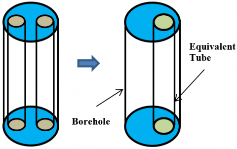
The equivalent tube diameter technique has been utilized by references [11-16]. Each of these investigators had his physical interpretation and justification for the technique followed by those researchers. In the present work, a similar idea is implemented for the representation of the U-tube by a single equivalent tube. Consider a vertical U-tube ground heat exchanger as shown in Figure 1a is to be transformed to an equivalent geometry configuration. The latter has an offset configuration with respect to the borehole center and possesses the same volume of grout as illustrated in Figure 1b.
a. Single U-tube b. Equivalent geometry
Figure 1. A schematic presentation of the present model
Therefore, an equivalent tube diameter to replace the two legs of the U-tube by keeping a constant volume of grout around the tube geometry was derived from:
$\frac{\pi}{4}\left\{D_{B}^{2}-2 d_{o}^{2}\right\} L=\frac{\pi}{4}\left\{D_{B}^{2}-d_{e}^{2}\right\} L$ (9)
Solving this equation yields to:
$d_{e}=\sqrt{2} d_{o}$ (10)
The transaction of the equivalent diameter $d_{e}=\sqrt{2} d_{o}$ to the offset position was achieved by keeping the offset shoulder defined by the following relation as a constant:
$y_{o}=\frac{D_{B}-S_{p}-d_{o}}{2}=\operatorname{const}$. (11)
This imposed condition was to ensure that the equivalent tube has a geometrical representation as close as possible to the original loop configuration. The offset distance of the equivalent diameter then calculated from:
$l_{p, e}=\frac{1}{2}\left(D_{B}-2 y_{o}-d_{e}\right)$ (12)
In which the equivalent tube offset distance lp,e obeys the following condition:
$d_{o}-r_{e} \leq l_{p, e} \leq r_{B}-r_{e}$ (13)
The offset distance of the equivalent tube is corresponding to (lp,e=do-re) when the U-tube legs are touching each other. The extreme case of the offset distance corresponds to (lp,e=rB-re) for the condition when the U-tube legs are touching the borehole wall.
Tarrad [19] found that the available one-dimensional correlations well predicted the borehole thermal resistance of a 3-dimensional borehole model with an accuracy margin of 5-18%. Hence, a one-dimensional heat transfer process between the fluid inside the tube and soil may be justified for preliminary borehole thermal analysis. The thermal resistance of an offset tube inside a cylindrical geometry with a length to be much bigger than the radius of the tube can be inferred with the help of the shape factor cited in Holman [20] as:
$R_{f}=\frac{1}{S_{f, e} k_{g}}$ (14)
$S_{f, e}=\frac{2 \pi L}{\cosh ^{-1}\left\{\frac{D_{B}^{2}+d_{e}^{2}-4 l_{p, e}^{2}}{2 D_{B} d_{e}}\right\}}$ (15)
Eq. (14) possesses the same tube loop and grout volumes, the mass flow rate of fluid inside the U-tube, and the same borehole geometry. Further, the same temperature conditions around the borehole will be kept constant as the original borehole geometry. This expression reveals that the grout thermal resistance shows a declination as the distance of U-tube legs increases. It approaches a minimum for given operating conditions and borehole configuration as the tubes are accommodated at the borehole wall where maximum heat absorption or dissipation would be expected. The heat conduction mode is the predominant factor in the thermal process of the borehole/soil combination. The grout layer that covers the tubes will be minimal when these tubes are situated close to the borehole wall and thus minimize the thermal resistance.
2.2 Ground and tube resistances
The equivalent diameter possesses the same convection resistance of the fluid flowing inside the original tube and its conduction resistance through the tube wall. Hence, the borehole thermal resistance is expressed as:
$R_{B}=R_{f}+R_{p}$ (16)
$R_{p}=\frac{1}{\pi d_{i} h}+\frac{\ln \left(\frac{d_{o}}{d_{i}}\right)}{2 \pi k_{p}}$ (17)
The unsteady analytical model presented by Garbai and Méhes [21] expressed the ground thermal resistance as follow:
$R_{S}=\frac{R_{B}}{2 k_{s}\left\{\frac{1}{\ln F 0-2 \gamma}-\frac{\gamma}{[\ln (4 F O-2 \gamma)]^{2}}\right\}}$ (18)
In which the parameter γ represents the Euler number and equal to 0.57. Applying Eq. (18) for a ground thermal conductivity of 2.42 W/m.K, they obtained the ground thermal resistance under the unsteady condition as shown in Table 1.
Table 1. Unsteady ground thermal resistance changes with time
|
Elapsed Time |
Ground Thermal Resistance (m. K/W) |
|
10 Second |
0.008 |
|
1 hr |
0.012 |
|
1 day |
0.022 |
|
1 month |
0.033 |
|
1 year |
0.053 |
|
10 years |
0.06 |
They concluded that a steady-state operation was attained after 1 year operation of a vertical U-tube ground heat exchanger. A value of 0.053 m.°C/W for ground thermal resistance was calculated for the steady-state conditions at a ground thermal conductivity of 2.42 W/m.K. Therefore, the total thermal resistance per unit length is estimated by:
$R_{t}=\frac{\cosh ^{-1}\left\{\frac{D_{B}^{2}+d_{e}^{2}-4 l_{p}^{2}}{2 D_{B} d_{e}}\right\}}{2 \pi k_{g}}+R_{p}++R_{S}$ (19)
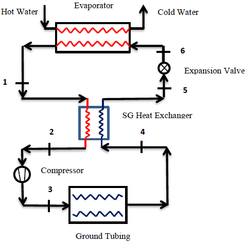
The model was utilized to estimate the U-tubing required to build a ground DX heat exchanger for 3.5 kW cooling load. Figure 2 depicts a layout of a heat pump to provide chilled water for cooling purposes with the following operating conditions:
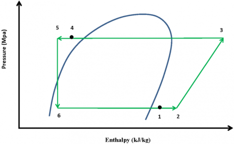
The p-h diagram of this system is shown in Figure 2b where the refrigerant is circulated through the on-ground and underground parts with specified operating conditions.
(a) A schematic diagram of the hypothetical heat pump system
(b) A (p-h) diagram of the hypothetical geothermal heat pump system [22]
Figure 2. A hypothetical Geothermal heat pump system [22]
3.1 Data analysis
The controlling mathematical relations for the thermal performance of the chiller were deduced from the first law of thermodynamics for the evaporator, condenser, expansion device, and compressor. The energy loss from the evaporator was assumed to be negligible for excellent thermal insulation. The evaporator load is represented by:
$\dot{Q}_{e v a p}=\dot{m}_{r e f}\left(h_{1}-h_{6}\right)$ (20)
The refrigerant enters the condenser as superheated gas; the superheat value depends on the refrigerant type and operating conditions. Thermodynamics yields the following relation:
$\dot{Q}_{\text {cond }}=\dot{m}_{r e f}\left(h_{3}-h_{4}\right)$ (21)
The results showed that to accomplish 1 ton of refrigeration in the evaporator, it requires about 0.98 kW to run the compressor. The refrigerant volumetric flow rate of R-410A is 3.39 m3/h at the compressor suction conditions. The available code known as CoolPack was implemented wherever it was needed to collect the physical properties of the analyzed refrigerants and assessment verification objectives [23].
3.2 Ground U-tubing
The objectives of the present work were focused on the assessment of U-tube heat exchanger geometry, borehole length to convey the condenser load and compare the results with other available correlations. The U-tube length is obtained for the general expression in the form:
$\dot{Q}_{\text {cond }}=\frac{L_{\text {tube }} \Delta T_{m}}{R_{t}}$ (22)
$\Delta T_{m}=T_{\text {ref }, m}-T_{S}$ (23)
The depth of the borehole corresponds to the calculated tube length from Eq. (22). In this context, the following issues were considered:
The illustrated geometry configurations in Table 2 were selected and assessed for condenser load of 4.4 kW.
Table 2. Geometry configurations for a single U-tube loop
|
Geo. |
do (mm) |
DB (mm) |
Sp/do (----) |
Sp (mm) |
Gref (kg/m2 s) |
de (mm) |
AU-tube (m2/m) |
|
G1 |
9.525 |
65 |
3.3 |
31.43 |
371.43 |
13.47 |
0.0599 |
|
G2 |
12.7 |
75 |
2-4.5 |
25.4-57.2 |
199.27 |
17.96 |
0.0798 |
The mass flux density and fluid flow velocity were calculated from:
$G_{r e f}=\frac{\dot{m}_{r e f}}{A_{c, i}}$ (24)
$V_{r e f}=\frac{G_{r e f}}{\rho_{r e f}}$ (25)
Eq. (25) could be used for both liquid and vapor phases with the utilization of the proper fluid density.
3.3 Heat transfer coefficient
Huang et al. [24] has reported data for condensation of R-410A/oil mixture at tube diameter of 5mm. The tests were conducted at a mass flux density range of 200 to 600 kg/m2 s and heat flux in the range of 4-19 kW/m2. The results showed that for condensation at 40℃, the heat transfer coefficient of pure R-410A was ranged between 2.4 to 4.6 kW/m2 ℃ measured for vapor quality range between 0.2 and 0.9 respectively. Kim and Shin [25] studied the condensation of R-410A in a 9.52mm outside diameter copper tube at a heat flux of 11 kW/m2. The tests were conducted at condensation temperature of 45°C, mass flux velocity of 273 to 287 kg/m2 s, and vapor quality of 0.1–0.9. The data presented a range between 2 and 3 kW/m2 ℃ for the heat transfer coefficient depending on vapor quality. For the present work assessment, a value of 3 kW/m2 ℃ was chosen for the condensation heat transfer coefficient of R-410A.
4.1 Tube size
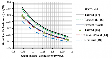
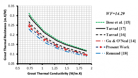
The predicted grout thermal resistance of the present work as expressed in Eq. (14) is compared with the previous correlations of references [14-18] in Figure 3.
(a) G1, grout specific resistance for tube WF=12.5
(b) G2, grout specific resistance for tube WF=14.29
Figure 3. Comparison of grout specific thermal resistance at (Sp/do) of 3.3
All correlations showed a similar data trend for the grout thermal resistance variation with thermal conductivity of filling. The thermal resistance of the backfill showed a reduction with grout thermal conductivity increase. The response of the present correlation for the geometry configuration variation is evident from Figure 3. The lowest thermal resistance was experienced at WF=14.29 whose tube outside diameter is 12.7mm. The bigger tube diameter, G2 revealed the lower thermal resistance. This condition was also confirmed previously by [4, 16, 17, 26, 27]. The trend of the prediction emphasized that increasing (do) reduces the grout thermal resistance and vice versa.
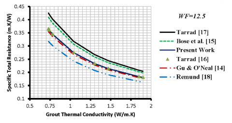
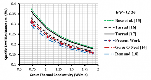
Figure 4 illustrates the comparison of specific total thermal resistance of the present work as presented in Eq. (18) with other investigators. These curves show that the total resistance decreases as the grout thermal conductivity increases. The highest and lowest thermal resistances were experienced at (kg) of 0.73 W/m.K and 1.9 W/m.K respectively. Remund [18] correlation resulted in the lowest thermal resistance; it is independent of the U-tube geometry.
(a) G1, specific total thermal resistance at tube WF=12.5
(b) G2, specific total thermal resistance tube WF=14.29
Figure 4. Comparison of specific total thermal resistance at (Sp/do) of 3.3
Bose et al. [15] correlation showed a response to the geometrical configuration and was higher for the small tube diameter, G1, than that of G2 as shown in Figure 4. Further, [15] correlation predicted the highest magnitudes for the thermal resistances than those of other correlations and was closer to those of [17]. The other tested correlations predicted closer values to each other, the present correlation produced close results to those of [14, 16, 18] and the discrepancy was negligible.
Tarrad [16] correlation predicted higher total thermal resistance than that of the present work for both U-tube geometries. It was higher than those of the present work by 13-17% and 13-16% for G2 and G1 configurations at Sp/do of 3.3 respectively. On the contrary, the present work predictions were higher than those of [18] by 4-5% and 11-15% for G2 and G1 configurations at a geometry ratio of 3.3 respectively. Gu and O’Neal [14] predicted higher total thermal resistance than those of the present work by 2-4% for G2. On the contrary, the present work predicted higher values than those of [14] by 2-3% for G1 configuration.
4.2 Tube diameter at fixed (Sp/do)
The response of the present correlation to the effect of different geometrical parameters was studied for the case where a fixed value of Sp/do was chosen for different tube diameters. In other words, for the case where different values of DB/dp were selected at fixed borehole diameter as illustrated in Table 3.
Figure 5 depicts the response of the present correlation to the effect of the ratio defined by DB/do and its comparison with other available expressions derived by Gu [14], Bose et al. [15] and Tarrad [16, 17]. All of these correlations showed the same trend of the predicted grout and total thermal resistance with DB/do. The general behavior of these curves was also confirmed by the work of Sagia et al. [26] in his numerical analysis and the prediction of ref. [27]. The trend of the data showed that at fixed borehole diameter and geometry ratio, increasing of DB/do, the thermal resistance exhibited an increase and vice versa. This is because decreasing the tube diameter results in the embedding of the tubes in a thicker grout layer and hence higher thermal resistance.
Table 3. Characteristics of examined geometries for fixed Sp/do and DB
|
do (mm) |
DB (mm) |
Sp/do (----) |
Sp (mm) |
DB/do (----) |
de (mm) |
|
9.52 |
75 |
2 |
19.04 |
7.88 |
13.47 |
|
12.7 |
75 |
2 |
25.4 |
5.91 |
17.96 |
|
15.88 |
75 |
2 |
31.75 |
4.724 |
22.46 |
|
19.05 |
75 |
2 |
38.1 |
3.937 |
26.94 |
(a) Borehole thermal resistance variation
(b) Total thermal resistance variation
Figure 5. A borehole and total thermal resistances variation with DB/do at Sp/do of 2 and fixed DB
The present model prediction for the borehole total thermal resistance is bounded by Tarrad [16] data as a minimum of 0.224 m.K/W and those of ref. [14, 15] as a maximum of 0.403 m.K/W for the test geometry configurations, Figure 5.
4.3 Tube spacing at fixed DB/ do
Table 4 shows the characteristics of the borehole geometries assigned for this purpose. A borehole diameter and tube outside diameter were chosen as 75mm and 12.7mm respectively. Eq. (10) shows that the thermal resistance is geometry dependent and grout thermal conductivity. The tube spacing was varied between 2 and 4 times the U-tube diameter.
Table 4. Characteristics of test geometries for fixed do and DB
|
do (mm) |
Sp (mm) |
Sp/do (----) |
DB (mm) |
Sp/DB (----) |
|
12.7 |
25.4 |
2 |
75 |
0.339 |
|
12.7 |
31.75 |
2.5 |
75 |
0.423 |
|
12.7 |
38.1 |
3 |
75 |
0.51 |
|
12.7 |
41.91 |
3.3 |
75 |
0.559 |
|
12.7 |
50.8 |
4 |
75 |
0.677 |
Figure 6 was produced to illustrate the effect of the tube spacing on the grout specific thermal resistance and hence on the total value which determines the ground heat exchanger size.
Figure 6. Variation of grout thermal resistance with U-tube legs spacing at fixed DB/do
The results for these borehole dimensions were compared between different correlations under the same geometry configuration. The correlations built [15, 16, 18] didn’t show any response to the geometry dimension variation, therefore they revealed constant values as straight horizontal lines as illustrated in Figure 6. The present correlation exhibited a good interaction with the geometry configuration and physical dimension of the borehole size. The thermal resistance of the grout and hence the borehole is a strong function of the spacing, U-tube size, and to some extent to the borehole diameter as confirmed by Bose [15] and Tarrad [17] and present work. The correlations of Bose [15] and Tarrad [17] and the present work showed the response of the thermal resistance to the tube spacing and diameter. As the tube spacing increases, the grout thermal resistance, borehole resistance, and the total borehole resistance also decrease. Their values approaching a minimum as the tubes reach closer to the borehole boundary, in this category the Sp/do equal to 4. This conclusion was also confirmed by [18] for the case where the U-tube legs were situated along the borehole surface. He found the minimum thermal resistance would be attained under these conditions.
4.4 Borehole depth
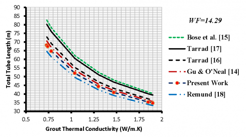
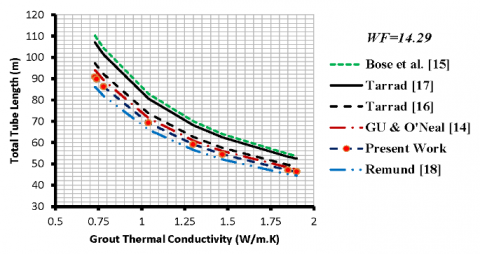
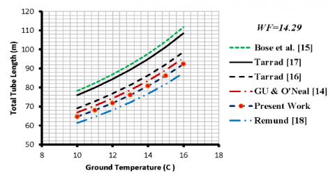
Figure 7 depicts a comparison of different model predictions for the total U-tube length at different ground temperatures 10 and 15℃ for condensation at 30℃. The higher the thermal conductivity of grout the shorter U-tube length will be required. The lower ground temperature revealed smaller tube lengths for all of the tested correlations and having the same data trend.
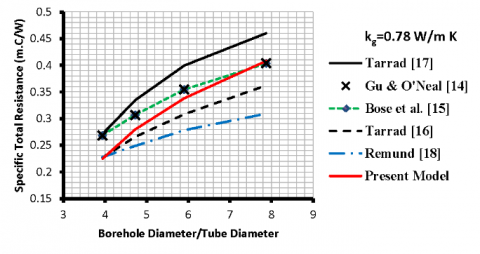
The assessment showed that the present work as illustrated in Eq. (19) predicted a U-tube total length which is close to that [14, 16, 18]. Bose et al. [15] and Tarrad [17] predicted the highest range of U-tube total length and they were close to each other by a margin of 2-3%. The predicted tube length for G2 of the present work at grout thermal conductivity of 0.78 W/m.K is compared with various correlations in Figure 8.
(a) G2, total U-tube length for $\Delta T_{m}$ 20℃
(b) G2, total U-tube length for $\Delta T_{m}$ 15℃
Figure 7. Comparison of predicted U-tube length between different models at Sp/do of 3.3
The calculated geometrical configurations for both geometries are compared in Table 5. High depths of boreholes were predicted by Bose [15] and Tarrad [17], whereas Remund [18] estimated the shortest U-tube length. This is due to the fact the earlier correlations predicted the highest thermal resistance of the borehole systems and the latter has predicted the lowest corresponding value, Figures 3, 4. The predicted values of depths were higher than those of [18] by 24-33% and 27-29% [15, 17] respectively, Table 4. The present work has also shown higher borehole depths than those of the [18] model by the range of 6-14%. The other correlations predicted a variety of U-tube lengths and were bounded by Tarrad [17] and Remund [18] predicted numerical values. The present correlation showed closer magnitudes of the U-tube length to those of Gu and O'Neal [14] and Tarrad [16] ones. The predicted depths by the present work were within the range of ±3% when compared with Gu and O'Neal [14] and were lower than those of Tarrad [16] by 1-6%. Whereas the predicted design values of Tarrad [17] were closer to those obtained by the model [15]. It should be pointed out that the size of the vapor phase side for condensers is usually designed to have a larger tube leg diameter than that of the liquid phase. This is to secure a proper velocity of the refrigerant through the U-tube ground heat exchanger. But the present work can give a proper tool for the preliminary design of the ground heat exchanger.
Figure 8. Comparison of U-tube length at kg of 0.78 W/m.K
Table 5. Borehole size and thermal resistances at kg=0.78 W/m.K, Sp/do of 3.3 and ΔTm =20℃
|
Model |
do (mm) |
DB (mm) |
Sp (mm) |
de (mm) |
Rf (m.°C/W) |
Rt (m.°C/W) |
Lt (m) |
As (m2) |
|
Present Work |
9.52 12.7 |
65 75 |
31.43 42.00 |
13.47 17.96 |
0.2784 0.2302 |
0.3448 0.293 |
76.1 64.8 |
2.277 2.585 |
|
Gu & O’Neal [14] |
9.52 12.7 |
65 75 |
31.43 42.00 |
17.3 23.1 |
0.270 0.2403 |
0.3364 0.3032 |
74.24 66.9 |
2.222 2.669 |
|
Bose et al. [15] |
9.52 12.7 |
65 75 |
31.43 42.00 |
13.47 17.96 |
0.3211 0.2916 |
0.3875 0.3544 |
85.6 78.25 |
2.561 3.122 |
|
Tarrad [16] |
9.52 12.7 |
65 75 |
31.43 42.00 |
16.50 21.99 |
0.280 0.2503 |
0.3461 0.3131 |
76.38 69.12 |
2.286 2.758 |
|
Tarrad [17] |
9.52 12.7 |
65 75 |
31.43 42.00 |
12.544 18.887 |
0.3357 0.2813 |
0.4020 0.3442 |
88.72 75.96 |
2.655 3.031 |
|
Remund [18] |
9.52 12.7 |
65 75 |
31.43 42.00 |
------- ------- |
0.235 0.2153 |
0.3014 0.2781 |
66.52 61.4 |
1.991 2.450 |
The tube length or the borehole depth of the ground heat exchanger represents a great challenge to the designer. This is due to the many factors that have an inevitable impact on the heat transfer rate between the fluid that is flowing inside the tube and ground conditions. Raising the discharge pressure of the compressor increases the saturation temperature of the refrigerant which increases the temperature difference between the fluid and ground. Simultaneously, such action will increase the heat load to be dissipated through the U-tube ground heat exchanger. Improving the grout thermal conductivity minimizes the need for long tubes. Further, the tube size has its effect on the tube length as well, smaller tubes create a higher obstruction to heat flow than those of big sizes and hence the length of the tube. The U-tube leg spacing should also be taken into consideration when sizing the borehole. Hence, optimization should be considered for the dimension selection of a ground heat exchanger and a compromise is approached with installation and operation costs.
A model was built to predict the borehole thermal resistance by replacing the U-tube with an equivalent tube positioned in an offset orientation with respect to the borehole center. The thermal resistance correlation possessed all of the geometrical parameters of the original U-tube/borehole configuration. The results showed that increasing of Sp/DB at fixed DB/do reduces the borehole thermal resistance and hence the depth of borehole for a specified heat load. The present work predictions were higher than those of [18] by 4-5% and 11-15% for G2 and G1 configurations at geometry ratio of 3.3 respectively. Gu and O’Neal [14] predicted higher total thermal resistance than those of the present work by 2-4% for G2 and it was lower than the present work by 2-3% for G1 configuration.
The predicted depths by the present work fell in the range of ±3% when compared with that of [14] for configuration G2 at Sp/do of 3.3. The work provides a good contribution to solve the design problem of the U-tube ground heat exchanger for preliminary sizing under steady-state operation.
The author expresses his sincere thanks to the administration of PAUSE program in France and the University of Lorraine for their valuable support to complete this work.
|
Parameter |
Definition |
|
A |
Surface area (m2) |
|
COP |
Coefficient of Performance |
|
d |
Tube diameter (m) |
|
D |
Diameter (m) |
|
FO |
Fourier number |
|
G |
Mass flux density (kg/m2 s) |
|
GSHP |
Ground source heat pump |
|
H |
Depth (m) |
|
k |
Thermal conductivity (W/m.K) |
|
lp |
Offset tube distance (m) |
|
L |
Length (m) |
|
$\dot{m}$ |
Mass flow rate (kg/s) |
|
$\dot{Q}$ |
Heat transfer rate (kW) |
|
r |
Radius (m) |
|
R |
Thermal resistance (m.K/W) |
|
Sf |
Geometry shape factor (m) |
|
Sp |
U-tube leg spacing (m) |
|
ΔT |
Temperature difference (K) |
|
V |
Fluid flow velocity (m/s) |
|
x |
Parameter defined by eq. (7) |
|
yo |
Distance between the borehole wall and tube (m) |
|
Subscriptions |
|
|
B |
Borehole |
|
c |
Cross-sectional |
|
cond |
Condenser |
|
e |
Equivalent |
|
f |
Filling, grout |
|
m |
Mean temperature difference between filling and ground |
|
g |
Grout |
|
i |
Inside |
|
o |
Outside |
|
p |
Pipe |
|
ref |
Refrigerant |
|
s |
Surface |
|
S |
Soil |
|
t |
total |
|
Greek letters |
|
|
$\beta$ |
Coefficient defined in Eq. (1) |
|
$\gamma$ |
Euler number |
|
$\rho$ |
Density (kg/m3) |
[1] Liao, Q., Zhou, C., Cui, W., Jen, T.C. (2012). Effective borehole thermal resistance of a single U-tube ground heat exchanger. Numerical Heat Transfer, Part A: Applications, 62(3): 197-210. https://doi.org/10.1080/10407782.2012.691061
[2] Sharqawy, M.H., Mokheimer, E.M., Badr, H.M. (2009). Effective pipe-to-borehole thermal resistance for vertical ground heat exchangers. Geothermics, 38(2): 271-277. https://doi.org/10.1016/j.geothermics.2009.02.001
[3] Haq, H.M., Martinkauppi, B.J., Hiltunen, E. (2017). Analysis of ground heat exchanger for a ground source heat pump: A study of an existing system to find optimal borehole length to enhance the coefficient of performance. WSEAS Transactions on Heat and Mass Transfer, 12(2017): 38-47.
[4] Florides, A.G., Christodoulides, P., Pouloupatis, P., (2012). An analysis of heat flow through a borehole heat exchanger validated model. Applied Energy, 92: 523-533. http://dx.doi.org/10.1016/j.apenergy.2011.11.064
[5] Muraya, N.K. (1994). Numerical modeling of the transient thermal interference of vertical U-tube heat exchangers. Doctoral dissertation, Texas A&M University.
[6] Rottmayer, S.P., Beckman, W.A., Mitchell, J.W. (1997). Simulation of a single vertical U-tube ground heat exchanger in an infinite medium (No. CONF-970668-). American Society of Heating, Refrigerating and Air-Conditioning Engineers, Inc., Atlanta, GA, United States.
[7] Zeng, H., Diao, N., Fang, Z. (2003). Heat transfer analysis of boreholes in vertical ground heat exchangers. International Journal of Heat and Mass Transfer, 46(23): 4467-4481. https://doi.org/10.1016/S0017-9310(03)00270-9
[8] Al-Khoury, R., Bonnier, P.G., Brinkgreve, R.B.J. (2005). Efficient finite element formulation for geothermal heating systems. Part I: Steady state. International Journal for Numerical Methods in Engineering, 63(7): 988-1013. https://doi.org/10.1002/nme.1313
[9] Koenig, A.A. (2015). Thermal resistance of borehole heat exchangers composed of multiple loops and custom shapes. Geothermal Energy, 3(1): 1-14. https://doi.org/10.1186/s40517-015-0029-1
[10] Chen, S., Mao, J., Han, X., Li, C., Liu, L. (2016). Numerical analysis of the factors influencing a vertical u-tube ground heat exchanger. Sustainability, 8(9): 882. https://doi.org/10.3390/su8090882
[11] Claesson, J. (1983). Heat extraction from the ground by horizontal pipes: a mathematical analysis. Document D1, Swedish Council for Building Research, Stockholm.
[12] Mei, V.C., Baxter, V.D. (1986). Performance of a ground-coupled heat pump with multiple dissimilar U-tube coils in series. ASHRAE Transactions, 92(2A): 30-42.
[13] Fischer, R.D., Stickford Jr, G.H. (1984). Technical and economic feasibility of horizontal, multiple shallow-well, and deep-well ground coupling for residential heat pump applications. Final Report Battelle Columbus Labs.
[14] Gu, Y., O'Neal, D.L. (1998). Development of an equivalent diameter expression for vertical U-tubes used in ground-coupled heat pumps. Transactions-American Society of Heating Refrigerating and air Conditioning Engineers, 104: 347-355.
[15] Bose, J.E., Parker, J.D., McQuiston, F.C. (1985), Design/Data manual for closed-loop ground-coupled heat pump systems; American Society of Heating, Refrigeration and Air Conditioning Engineers (ASHRAE).
[16] Tarrad, A.H. (2020). A perspective model for borehole thermal resistance prediction of a vertical U-tube in geothermal heat source. Athens Journal of Technology and Engineering, 7(2): 73-92. https://doi.org/10.30958/ajte.7-2-1
[17] Tarrad, A.H. (2019). A borehole thermal resistance correlation for a single vertical DX U-tube in geothermal energy application. American Journal of Environmental Science and Engineering, 3(4): 75-83. https://doi.org/10.11648/j.ajese.20190304.12
[18] Remund, C.P. (1999). Borehole thermal resistance: laboratory and field studies. ASHRAE Transactions, 105: 439-445.
[19] Tarrad A.H. (2021). A 3-Dimensional numerical thermal analysis for the configuration effect of a single and double U-Tube on the borehole performance. Proceedings of the ASME 2021 15th International Conference on Energy Sustainability ES2021, Paper No: ES2021-60659. https://doi.org/10.1115/ES2021-60659
[20] Holman, J.P, (2010), Heat Transfer, 10th edition, Published by McGraw-Hill. Chapter, 3: 83-86.
[21] Garbai, L., Méhes, S. (2008). Heat capacity of vertical ground heat exchangers with single U-tube installation in the function of time. WSEAS Transactions on Heat and Mass Transfer, 3(3): 177-186.
[22] Tarrad, A.H. (2019). The utilization of renewable energy source and environment friendly refrigerants in cooling mode. Sustainable Energy, 7(1): 6-14. https://doi.org/10.12691/rse-7-1-2
[23] Technical University of Denmark (DTU). (2001). CoolPack Software: A Collection of Simulation Tools for Refrigeration, Denmark.
[24] Huang, X., Ding, G., Hu, H., Zhu, Y., Gao, Y., Deng, B. (2010). Condensation heat transfer characteristics of R410A–oil mixture in 5 mm and 4 mm outside diameter horizontal microfin tubes. Experimental Thermal and Fluid Science, 34(7): 845-856. https://doi.org/10.1016/j.expthermflusci.2010.01.013
[25] Kim, M.H., Shin, J.S. (2005). Condensation heat transfer of R22 and R410A in horizontal smooth and microfin tubes. International Journal of Refrigeration, 28(6): 949-957. https://doi.org/10.1016/j.ijrefrig.2005.01.017
[26] Sagia, Z., Stegou, A., Rakopoulos, C. (2012). Borehole resistance and heat conduction around vertical ground heat exchangers. The Open Chemical Engineering Journal, 6: 32-40. http://dx.doi.org/10.2174/1874123101206010032
[27] Shonder, J.A., Beck, J.V. (1998). Determining effective soil formation thermal properties from field data using a parameter estimation technique. ASHRAE Transactions, 105: 458-466.