Durgesh Nandan* | Anurag Mahajann | Jitendra Kanungo
© 2021 IIETA. This article is published by IIETA and is licensed under the CC BY 4.0 license (http://creativecommons.org/licenses/by/4.0/).
OPEN ACCESS
An applications of signal processing are frequently used everywhere in day-to-day life. “Digital Signal Processing (DSP)” has been basic requirement of efficient and accurate arithmetic operations for performing fast and accurate signal processing. Logarithm arithmetic provides an option of that desire. In this work, it is presented an efficient VLSI implementation of an antilogarithm converter by using 10-region error correction. It provides error efficient implementation with significant hardware gain. VLSI implementation of reported and proposed antilogarithmic converters design created in Xilinx ISE 12.1. Antilogarithmic converters (reported and proposed design) are synthesized by using Synopsys design software perform the RTL Synthesis analysis by using package design compiler. This paper presents 10- region converter which considers design trade-off where proposed demonstrates 19.75%, 31.02%, 12.65%, 44.65% and 29.91% respective reduction in comparison of previous design. Error analysis was done using MATLAB for proposed conversion method and reported methods. Suggested antilogarithmic converters have 1.559% error only in comparison of 1.7327% error reported by Kuo et al. On behalf of hardware complexity and error analysis results, it can say that the proposed converters could perform better in comparisons of all aspects of reported design.
antilogarithmic converter, digital signal processing, error analysis, logarithmic converter, logarithmic multiplication, Mitchell method
A DSP application in a real time domain is a superset of an arithmetic operation. From literature, it is well known fact that binary arithmetic is accurate and hardware efficient [1, 2]. Logarithm offers an option to digital designers that they can substitute of binary operations over arithmetic. It performs multiplications operation via additions, due to this process lot of computation efforts save in comparison of reported arithmetic [3-5]. Logarithmic operations have nowadays become a good choice because it has an efficient hardware architecture in comparisons of binary arithmetic operations but, it has less accuracy in comparison with binary arithmetic [6].
Logarithmic number system (LNS) arithmetic operations are consisting of following essential stages: Logarithm conversion; arithmetic operation stages; and vice versa [7, 8]. Method of converting logarithmic/antilogarithmic is dominating factor of performance in terms of hardware and accuracy efficiency of LNS based arithmetic circuits [9, 10]. Antilogarithmic conversion is an accuracy deciding factor, so it created necessity of accurate converter to speed up arithmetic operation performance [11, 12].
In 1962, for the first time, Mitchell proposed add and shifted operation-based algorithm for multiplication by using the single region piecewise linear approximation. It presented first time a logarithmic and antilogarithmic converter. The “Average Error Percentage (AEP)” was 3.85% whereas the error range was varying up to 11.11%. It yielded maximum decrement in percentage error from 11.1 to 1.3 with high accuracy considering identical time penalty of speed with high level power requirement, and “hardware complexity” [6]. Error percent of Mitchell’s method 1-region antilogarithm converter are displayed in Figure 1.
Figure 1. Mitchell’s method by using 1-region antilogarithm converter with error percent
In 1970, multiple regions linear approximation was proposed by Hall et al. [13], but main drawback of this design is suffered from hardware inefficiency. “Hall’s algorithm” used all bits in the mantissa for error adjustment and for achieving this applying linear piecewise approximation. In 1999, SanGregory et al. [14] presented small and fast algorithm using four “Most Significant Bits (MSB)s” of mantissa for bits adjustment. The “antilogarithm” equation by using “2-region correction” proposed by SanGregory’s was the conversion methods which improved accuracy of previous algorithms using “Read Only Memory (ROM)”. Multiple region logarithmic / antilogarithmic converter proposed by Abed et al. [11, 12] with low errors, at the penalty of higher area costs. It offered on the utilization of ROM circuits for hardware minimization. The highest obtained error during of this conversion process was up to 1.5%. Abed and Siferd suggested correction that produced better results in term of accuracy, speed, and complexity. Correction strategies used for 2, 6, and 7 regions with changing hardware complexity and accuracy [12]. In 2004, a 2-region error manipulation schemes were proposed by Juang et al. [15, 16] and advancement of this work is introduced for logarithmic and antilogarithmic converter. Juang et al. [16] have proposed 2-region correction by using bit level manipulation schemes to achieve trade-off. Same concept is used for an “antilogarithm conversion”. 2 region logarithm approximations maximum error ranges from 0 to 0.0319 and -0.60 to 1.72 for “antilogarithm converter”, respectively. In 2012, Kuo and Juang [17] proposed four-region “antilogarithmic converter” using “piecewise-linear approximation”. In 2015, Juang et al. [18, 19] and in 2016, Durgesh et al. presented 2-region antilogarithm approximation in antilogarithm converter for the range of -0.60 to 1.72 where recorded error range was 2.32%. Furthermore, in 2016, Kuo et al. [20] presented for multiple regions by using constant compensation scheme for error minimization which reported 1.83%, 1.34% and 0.61% error, respectively with multiple regions at the cost of hardware penalty. In 2017, Durgesh et al. [21] suggested efficient architecture of antilogarithm converter for 11-region at same error cost . In 2019, Durgesh and his research team suggested 16 regions based “error correction scheme” for “antilogarithm converter” [22]. In 2020, Durgesh and his research team suggested multi regions “error correction scheme” “antilogarithm converter” for DSP processor [23]. For error minimization circuit in antilogarithm converter when it is increases the number of regions, hardware cost increasing and errors are decreasing. It motivates the researchers to work for best alternatives with fulfill the trade-off between accuracy and hardware cost. In this paper, it is proposed a 10-region antilogarithmic converter with error correction scheme where the balance between exactness and hardware costs has been met.
The arrangement of an article is like that: Section 3 presents reported antilogarithmic mathematical concepts. Section 4 describes proposed methodology and detailed hardware architecture. Section 5 explains error and hardware efficiency outcomes and comparative review. The paper is concluded in section 6 where outcomes and limitations of proposed antilogarithmic converter are elaborated.
Let $Z$ be a binary number for fixed interval range $2^{a+1} \leq$ $Z \geq 2^{b}$ and $a \geq b$. Now, the $Z$ will be represented as Eq. (2):
$Z={{2}^{a}}(1+\sum\limits_{i=b}^{a-1}{^{\mathop{2}^{i-a}}}{{z}_{i}})$ (1)
where, $a$ is considered as fraction part and its lies between 0 to 1. The logarithm called true logarithm of Z is represented by:
$\lg (Z)true=a+\lg (1+x)$ (2)
The $\lg (1+x)$ value was approximated by Mitchell's method. $x$ is the fraction value called as approx logarithm and it's represented in Eq. (3):
$\lg (Z)approx=a+x$ (3)
The antilogarithm results the final product, $P$ logarithm which is represented as follows:
$P{{=}_{2}}a\text{ }(1+x)$ (4)
Kuo et al. proposed constant compensation scheme for error minimization. It achieved error was 1.83%, 1.34% and 0.61% with “11-region”, “14-region” and “28-region”, respectively [20]. Eq. (5) shows the constant compensation scheme and Eq. (6) shows the compensation value (c).
$\begin{align} & \text{Antilog(A)=}{{\text{2}}^{\text{A}}}\text{=}{{\text{2}}^{\text{p}}}\times {{2}^{m}}={{2}^{m}}(1+m+c\text{), } \\ & \text{Where 0}\le m\text{1} \\ \end{align}$ (5)
$\text{c = }\pm \sum\limits_{j}{{{2}^{-j}}}\text{,}$ (6)
where, j denotes positive numbers.
In order to improve the error in any straight line, an approach has been employed in which addition of difference between “approximated value” and “actual value”. But, the simple process of adding the difference of “approximated value” minus “actual value” is not able to much exact result. Also, in many cases it is observed that the variation of error in different segment results different percentage of error, i.e. error is not uniform in all condition [18]. For substantial error minimization, split straight lines into several regions and add the average correction difference in a given range. The key concern, however, is that increased hardware penalty is increased in subdivisions. Our main objective of this paper is error minimization with significant hardware gain.
4.1 Proposed method
The proposed method is approximated by the following Eq. (7), and “error percent” is representing in Eq. (8). It is based on the piecewise-linear approximation concepts.
$\text{Y}={{2}^{k}}{{2}^{m'}}={{2}^{k}}(ax+b)$ (7)
$\text{Percent Error}=(\frac{(ax+b)-{{2}^{x}}}{{{2}^{x}}})\times 100,\text{ 0}\le \text{x1}$ (8)
Here, Percentage error is explained as the approximated value percentage minus actual value divided by actual value. The approximation errors for each sub regions can be obtained using Mitchell’s method [5]. The proposed design of antilogarithmic converter may be formulated as Eq. (9) and error correction value (ECV) can be like as Eq. (10).
$Anti\log (A)={{2}^{A}}={{2}^{p}}\times {{2}^{x}}={{2}^{x}}(1+x+c),\text{ }0\le x<1$ (9)
$\text{ECV = c = }\pm \sum\limits_{i}{{{2}^{-i}}},$ (10)
where, i is a positive integer. The Figure 2 shows the algorithm for the obtainment of optimum error coefficients in the proposed Anti-logarithmic converter.
Figure 2. The optimal error correction coefficient algorithm
We can use the proposed algorithm for finding “error correction coefficient” for the “10-regions” “antilogarithmic converter”. By using a given algorithm in Figure 2, 10-regions of “approximate schemes” can be represented as Eq. (11), and the “compensation values” as shown below in Table 1.
For easy understanding, if N=10, then ‘K’ can be partitioned into [0, 0.055), [0.055, 0.115), [0.115, 0.187), [0.187, 0.260), [0.260, 0.374), [0.374, 0.670), [0.670, 0.78), [0.78, 0.875), [0.875, 0.955) and [0.955, 1.00), respectively. Here, ‘i’ partitioned in that way which can create a minimum error as well as fewer hardware requirements also. After extracting the “optimal error correction” coefficient values for every region, the manual adjustment process is adopted to fine tune the process in order to get the minimum “percent errors” for entire range.
${{\text{A}}_{\text{proposed}}}\text{=}{{\text{2}}^{\text{p}}}\times {{2}^{x}}\approx {{2}^{\text{p}}}(1+x+\text{c), 0}\le \text{x1}$ (11)
By the help of Table 2, for the corrected values of 2-4, 2-5, 2-6, and 2-7 K-map can be drawn.
For 10- regions corrected values of 2-4, 2-5, 2-6 and 2-7.
s1= m-1 and m-2;
s2= s1 and (not m-3) and m-4;
s3= m-1 and (not m-2);
s4= (not m-1) and m-2;
n-4= s3 or (s4 and m-4) or (m-3 and s4);
n-5 = (s4 and m-3 and m-4) or s2 or ((not m-1) and (not m-2) and m-3);
n-6 = s1 or (s4 and (not m-3) and (not m-4) or ((not m-2) and (not m-3) and m-4) or (s3 and (not m-3)); n-7 = s2;
On the basis of simplified equation found by k-map we can able to decide the hardware architecture of circuit.
4.2 Hardware implementation
The proposed “antilogarithm converter” architecture by using “10-region” “error correction scheme” is shown in Figure 3. Part (a) of Figure 3 shows the architecture of sub-component which has 4 inputs and 4 outputs based on K-map of corrected values and (b) provides the principal block of 10-region error correction circuit. It is combination of “Full subtraction (FS)”, “Half subtraction (HS)” and “Modified subtraction (MS)”.
Table 1. Subtraction terms of various regions for proposed “antilogarithm converters” using “10-region error correction schemes
|
Items |
“Fractional region” |
Subtraction terms |
Items |
“Fractional region” |
Subtraction terms |
|
1 |
[0, 0.055) |
0 |
6 |
[0.374, 0.670) |
-(1/16+1/64) |
|
2 |
[0.055, 0.115) |
-(1/64) |
7 |
[0.670, 0.780) |
(1/16) |
|
3 |
[0.115, 0.187) |
-(1/32) |
8 |
[0.780, 0.875) |
-(1/32+1/128) |
|
4 |
[0.187, 0.260) |
-(1/32+ 1/64) |
9 |
[0.875, 0.955) |
-(1/64) |
|
5 |
[0.260, 0.374) |
-(1/16) |
10 |
[0.955, 1) |
0 |
Table 2. 10- region corrected values
|
m-1(=0) m-2 m-3m-4 |
“Corrected value” |
m-1(=1) m-2 m-3m-4 |
“Corrected value” |
||||||
|
2-4 |
2-5 |
2-6 |
2-7 |
2-4 |
2-5 |
2-6 |
2-7 |
||
|
000 |
0 |
0 |
0 |
0 |
001 |
1 |
0 |
1 |
0 |
|
001 |
0 |
0 |
1 |
0 |
010 |
1 |
0 |
1 |
0 |
|
010 |
0 |
1 |
0 |
0 |
011 |
1 |
0 |
1 |
0 |
|
011 |
0 |
1 |
0 |
0 |
100 |
1 |
0 |
0 |
0 |
|
100 |
0 |
1 |
1 |
0 |
101 |
0 |
0 |
0 |
0 |
|
101 |
1 |
0 |
0 |
0 |
110 |
0 |
1 |
0 |
1 |
|
110 |
1 |
0 |
1 |
0 |
111 |
0 |
0 |
1 |
0 |
|
111 |
1 |
0 |
1 |
0 |
000 |
0 |
0 |
1 |
0 |
(a)
(b)
Figure 3. (a) “Combined circuit” of corrected value and (b) Principal block of 10-region error correction circuit
4.3 Error analysis
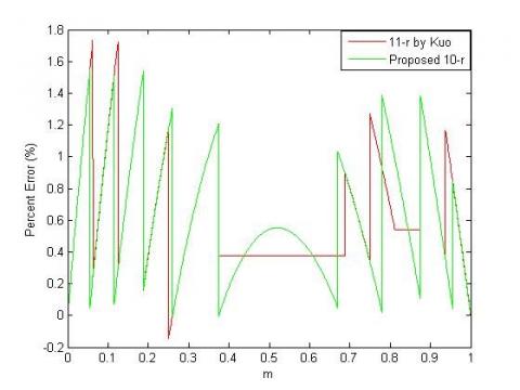
As we realize that Error investigation is the primary worry in logarithm arithmetic on the grounds that it has effectively limited design in correlations of binary arithmetic. Here, based on available equation, simulation is done by MATLAB software. The MATLAB graphs for the proposed method with 10-regions error corrector scheme and antilogarithm converter using 11- regions converter with constant compensation scheme is shown in Figure 4.
Figure 4. Analysis of percent error by using proposed 10-region error correction circuit with reported 11-region
By using proposed method every “sub-region” has less “error percentage” in comparison to past presented method. Error will be calculated based on three parameters, the “Maximum Positive Percent Error (MPPE)”, “Maximum Negative Percent Error (MPPE)” and the “Percentage Error Range (PER)”. Table 3 has been shown findings. The proposed method by using 10-regions “error correction scheme” gives 1.554% in comparisons of “Mitchell’s” 6.1476%, “Juang” et al. “2-region” 1.72% and “Kuo” et al. “11-region” 1.7327% MPPE and gives -0.00509% in comparisons of “Mitchell’s” 0%, Juang et al. “2-region” -0.6% and Kuo et al. “10-region” -0.0992% MNPE. The proposed method by using “10-regions” “error correction scheme” gives 1.559% in comparisons of “Mitchell’s” 6.1476%, “Juang” et al. “2-region” 2.3232% and “Kuo” et al. “11-region” 1.8319%. After careful observation of Table 3, it found that proposed method has 24.89% less “error percentage” in comparisons of existing designs [16].
Table 3. Error comparisons table of various reported and proposed architecture
|
|
Regions |
MPPE |
MNPE |
PER |
|
Mitchell’s straight-line 5 |
1 |
6.1476 |
0 |
6.1476 |
|
Juang 14 |
2 |
1.72 |
-0.6 |
2.3232 |
|
Kuo 16 |
11 |
1.7327 |
-0.0992 |
1.8319 |
|
Proposed (10-Regions) |
10 |
1.554 |
-0.00509 |
1.559 |
Tabularly 4 presents theoretical and hardware-complexity analyses for simple gates and reported structures for 10-regions antilogarithm error correction scheme. It is revealed from the Table 4 that the employed set of gates i.e., AND, OR, NOT and XOR in the proposed antilogarithm converter structure by utilizing 10-regions error correction scheme are 25,11, 15 and 10, respectively whereas in 11 region constant compensation scheme the employed gates were 35, 15, 26 and 13, respectively. It means that the proposed structure employs 10 less “AND” gates, 4 less “OR” gate, 11 less “NOT” gates and 3 less “XOR” gates. Consequently, through study of “theoretical hardware complexities”, we can say that the “10-region” “error correction scheme” proposed is more hardware efficient compared to the “11-region” permanent compensation scheme that has been published.
5.1 Synthesis results
The “Synopsys design compiler” with “TSMC 65 nm CMOS library” is employed in order to design and evaluate the proposed antilogarithm converter by using 10-regions structure and 11-region “constant compensation scheme”, was employed. The parameters, “Data arrival time (DAT)”, area, power, “Area delay product (ADP)”, and Energy, are compared for the proposed and the reported structures [14] and [16] are as listed in Table 5. The reported results for proposed “antilogarithm converter” by using “10-regions error corrector scheme” shows 19.75%, 31.02%, 12.65%, 44.65% and 29.91% improvement in DAT, area, Power, ADP and engery respectively when compared to the existing antilogarithmic converter scheme in [16]. On the basis of error analysis, theoretical hardware complexity analysis and simulation results, it can well understand that proposed “10 regions” “antilogarithm converter” is better than reported antilogarithm converter in every aspect.
Table 4. General comparisons of “hardware complexities” of reported 11-regions and proposed “10-regions error correction circuit”
|
Structure |
Antilogarithm Existing16 |
Antilogarithm Proposed |
|
AND |
35 |
25 |
|
OR |
15 |
11 |
|
NOT |
26 |
15 |
|
XOR |
13 |
10 |
Table 5. Synopsys DC Compiler synthesis results of proposed 10-region error correction circuit and reported structures
|
Structure |
DAT (ns) |
Area (µm2) |
Power (µW) |
ADP (µm2*n) |
% gain in ADP |
Energy (n J) |
% gain in Energy |
|
Reported (11-region) 16 |
0.81 |
203.04 |
4.068 |
164.46 |
--------- |
3295.08 |
---------- |
|
Reported (2-region) 14 |
0.67 |
109.80 |
3.393 |
73.56 |
---------- |
2273.31 |
---------- |
|
Proposed |
0.65 |
140.04 |
3.553 |
91.02 |
44.65 |
2309.45 |
29.91 |
In this paper, “antilogarithmic converter” by using 10-region “error correction schemes” had suggested with best possible trade-off in comparison of reported designs. It demonstrates 24.898% percentage error reduction when compared to the proposed design of Juang et al. [16]. In terms of ADP and low energy correlations, the proposed converter with 10-regions shows 44.65% and 29.91%, respectively from existing 11-regions antilogarithm converter. It has 32.89% less error at the cost of 23.73% ADP penalty in comparison to Juang et al. 2-region “antilogarithm converter”. The proposed 10-region “error correction schemes” for “antilogarithmic converter” can be used for real-time DSP based applications.
[1] Saha, P., Banerjee, A., Dandapat, A., Bhattacharyya, P. (2014). High speed multiplier using high accuracy floating point logarithmic number system. Scientia Iranica Transactions D: Computer Science & Engineering and Electrical Engineering, 21(3): 826-841.
[2] Basetas, C., Kouretas, I., Paliouras, V. (2007). Low-power digital filtering based on the logarithmic number system. Proc.17th Workshop Power and Timing Modeling, Optimization and Simulation, LNCS4644, pp. 546-555.
[3] Mahalingam, V., Rangantathan, N. (2006). Improving accuracy in mitchell's logarithmic multiplication using operand decomposition. IEEE Transactions on Computers, 55(2): 1523-1535. https://doi.org/10.1007/978-3-540-74442-9_53
[4] Nandan, D., Kanungo, J., Mahajan, A. (2017). An efficient VLSI architecture design for logarithmic multiplication by using the improved operand decomposition. Integration, 58: 134-141. https://doi.org/10.1016/j.vlsi.2017.02.003
[5] Nandan, D., Kanungo, J., Mahajan, A. (2018). An errorless Gaussian filter for image processing by using expanded operand decomposition logarithm multiplication. Journal of Ambient Intelligence and Humanized Computing, 1-8. https://doi.org/10.1007/s12652-018-0933-x
[6] Mitchell, J.N. (1962). Computer multiplication and division using binary logarithms. IRE Transactions on Electronic Computers, (4): 512-517. https://doi.org/10.1109/TEC.1962.5219391
[7] Paul, S., Jayakumar, N., Khatri, S.P. (2008). A fast hardware approach for approximate, efficient logarithm and antilogarithm computations. IEEE Transactions on Very Large Scale Integration (VLSI) Systems, 17(2): 269-277. https://doi.org/10.1109/TVLSI.2008.2003481
[8] Nandan, D., Kanungo, J., Mahajan, A. (2018). 65 years journey of logarithm multiplier. International Journal of Pure and Applied Mathematics, 118(14): 261-266.
[9] Nandan, D., Kanungo, J., Mahajan, A. (2017). An efficient VLSI architecture for iterative logarithmic multiplier. In 2017 4th International Conference on Signal Processing and Integrated Networks (SPIN), pp. 419-423. https://doi.org/10.1109/SPIN.2017.8049986
[10] Nandan, D., Kanungo, J., Mahajan, A. (2018). An efficient architecture of iterative logarithm multiplier. International Journal of Engineering & Technology, 7(2-16): 24-28. https://doi.org/10.14419/ijet.v7i2.16.11410
[11] Abed, K.H., Siferd, R.E. (2003). CMOS VLSI implementation of a low-power logarithmic converter. IEEE Transactions on Computers, 52(11): 1421-1433. https://doi.org/10.1109/TC.2003.1244940
[12] Abed, K.H., Sifred, R.E. (2003). CMOS VLSI implementation of a low-power antilogarithmic converter. IEEE Transactions Computers, 52(11): 1221-1228.
[13] Hall, E.L., Lynch, D.D., Dwyer, S.J. (1970). Generation of products and quotients using approximate binary logarithms for digital filtering applications. IEEE Transactions on Computers, 100(2): 97-105. https://doi.org/10.1109/T-C.1970.222874
[14] SanGregory, S.L., Brothers, C., Gallagher, D., Siferd, R. (1999). A fast, low-power logarithm approximation with CMOS VLSI implementation. In 42nd Midwest Symposium on Circuits and Systems (Cat. No. 99CH36356), pp. 388-391. https://doi.org/10.1109/MWSCAS.1999.867287
[15] Juang, T.B., Chen, S.H., Cheng, H.J. (2009). A lower error and ROM-free logarithmic converter for digital signal processing applications. IEEE Transactions on Circuits and Systems II: Express Briefs, 56(12): 931-935. https://doi.org/10.1109/TCSII.2009.2035270
[16] Juang, T.B., Meher, P.K., Jan, K.S. (2011). High-performance logarithmic converters using novel two-region bit-level manipulation schemes. In Proceedings of 2011 International Symposium on VLSI Design, Automation and Test, pp. 1-4. https://doi.org/10.1109/VDAT.2011.5783555
[17] Kuo, C.T., Juang, T.B. (2012). A lower error antilogarithmic converter using novel four-region piecewise-linear approximation. In 2012 IEEE Asia Pacific Conference on Circuits and Systems, pp. 507-510. https://doi.org/10.1109/APCCAS.2012.6419083
[18] Juang, T.B., Kuo, H.L., Jan, K.S. (2016). Lower-error and area-efficient antilogarithmic converters with bit-correction schemes. Journal of the Chinese Institute of Engineers, 39(1): 57-63. https://doi.org/10.1080/02533839.2015.1070692
[19] Nandan, D., Kanungo, J., Mahajan, A. (2016). An Efficient VLSI architecture design for antilogarithmic converter by using the error correction scheme. IET International Conference on Signal Processing (ICSP), SATI, India. https://doi.org/10.1049/cp.2016.1445
[20] Kuo, C.T., Juang, T.B. (2018). Area-efficient and highly accurate antilogarithmic converters with multiple regions of constant compensation schemes. Microsystem Technologies, 24(1): 219-225. https://doi.org/10.1007/s00542-016-3238-z
[21] Nandan, D., Mahajan, A., Kanungo, J. (2017). An efficient antilogarithmic converter by using 11-regions error correction scheme. In 2017 4th International Conference on Signal Processing, Computing and Control (ISPCC), pp. 118-121. https://doi.org/10.1109/ISPCC.2017.8269661
[22] Nandan, D., Kumar, K., Kanungo, J., Mishra, R.K. (2019). Compact and errorless 16-region error correction scheme for antilogarithm converter. In 2019 International Conference on Electrical, Electronics and Computer Engineering (UPCON), pp. 1-5. https://doi.org/10.1109/UPCON47278.2019.8980240
[23] Nandan, D. (2020). An efficient antilogarithmic converter by using correction scheme for DSP processor. Traitement du Signal, 37(1): 77-83. https://doi.org/10.18280/ts.370110