Mohamed Salmi | Abdelhakim Boursas | Mederreg Derradji | Giulio Lorenzini* | Hijaz Ahmad | Younes Menni | Houari Ameur | Rachid Maoudj
© 2021 IIETA. This article is published by IIETA and is licensed under the CC BY 4.0 license (http://creativecommons.org/licenses/by/4.0/).
OPEN ACCESS
In the current study, this way was adopted numerically in order to optimize the performance of a HEC through the use of extended solid sections in the form of 'W' (W-baffles: WBs). All limit conditions of the channel have been defined, with all the thermo-physical properties of the HTF (heat transfer fluid) used. The FVM (Finite-Volume-Method) has been adopted with some necessary numerical schemes in order to give the numerical solution, which allows us to visualize dynamically the flow filed and to deduce all the energetic characteristics contained by this HE. Dynamically, the HTF flow velocity at the HEC outlet section reached about 1.812 m/s, in the case of the lowest Re value. While, it passed 4.8 m/s in the case of the largest value of the same variable, i.e. 1.726 to 4.648 times better than the Uin within the limits of Re numbers used. Thermally, areas with very hight TGs (temperature gradients) were observed near the top deflector’s sides, which reflects the effect of the W-baffles. This highlights the importance of the adopted obstacles in changing characteristics of the HEC to the best.
numerical simulation, channel heat exchanger, w-shaped baffles, air heat transfer fluid, flow field
The arrangement of obstacles, such as baffles, fins, and ribs, within channels, are among the effective methods used by many researchers and investigators in their numerical and experimental studies. For example, see Berner et al. [1], Habib et al. [2], Yuan et al. [3], Cheng and Huang [4], Hong and Hsieh [5], Bazdidi-Tehrani and Naderi-Abadi [6], Demartini et al. [7], Li and Kottke [8], Mousavi and Hooman [9], Pirouz et al. [10], Mokhtari et al. [11], Webb and Ramadhyani [12], Wen et al. [13], Dong et al. [14], Skullong et al. [15], Thianpong et al. [16], Nanan et al. [17], Promvonge [18], Du et al. [19], and Menni et al. [20-30]). These studies have adopted many obstacles in various forms to give channels with high energy efficiency.
Moreover, some studies contributed to the nanometer and other fluids for different ducts of various application systems. For example, see Kolsi [31], Rashad [32], Ghalambaz et al. [33], Ismael [34], Selimefendigil [35], Ashham et al. [36], Alsabery et al. [37], and Hajjar et al. [38]. Other predictions have treated both heat and mass transfer in different flow conditions using nuerical and experimental methods. For example, see Kolsi [39], Rashad [40], Ismael and AI-Rabeh [41], Selimefendigil [42], Ghalambaz et al. [43], Mehryan et al. [44], Azmi et al. [45], and Menni et al. [46-54].
The ongoing study adopted a new flow behavior based on a modern design for the obstacles by giving them an attractive geometrical model. They are the W-shaped obstacles. These deflectors create a different flow structure, which causes the scales inside the channel to change, due to their complex structural shape. It is important to note that this type of obstacle has not been used a lot, especially numerically. For this, we will try as much as possible to diagnose the air in the different base stations present. We will study carefully:
2.1 Problem statement
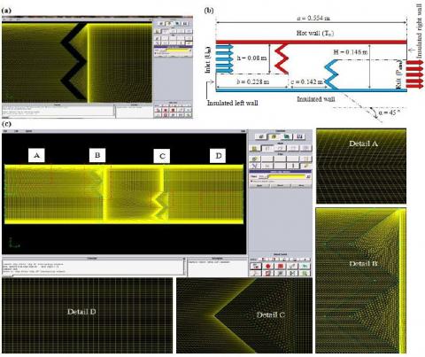
To intensify the augmentation in the heat transfer between the hot wall and the AHTF (Air Heat Transfer Fluid), a W-Baffle has been represented. Figure 1(a) shows the corresponding geometry. In our study, the channel mentioned in Ref. [7] has been updated through:
This updated channel is shown in Figure 1(b) with all the boundary conditions to which it is subject. Also, the various stations of the updated channel have been meshed, as shown in Figure 1(c).
2.2 Characteristics and boundary conditions
To ensure a correct numerical solution, and to avoid diverging in the numerical model, the following has been adopted:
2.3 Numerical models
The modeled governing equations, the used simulation software, the employed grid generation preprocessor, the adopted numerical method, the selected discretization algorithm, and the various followed CFD schemes are presented in [55, 56].
Figure 1. (a) W-baffle geometry, (b) updated channel and (c) Mesh system
In the first part of this study, various AHTF fields, i.e., dynamic pressure (Pd), mean velocity (V), turbulent-kinetic-energy (k) and turbulent intensity (TI), as well as thermal behavior fileds, i.e., isotherms (T) were analyzed. Reynolds’ values (Re) used to analyze these fields are restricted to the range, from 12 × 103 to 3.2 × 10⁴.
The newly used design allows the flow path to be changed, from straight to wavy, see Figure 2. This change in behavior is due to the presence of the WBs. The complex geometry of these WBs changes Pd value from one station to another. As mentioned, it is very high above the lower WB (about 17 Pa), considered below the top WB (approximately 12 Pa), while it is low in the rest of the stations. This quantitative difference in terms of Pd values is evident for the high Re values. Moreover, the maximum Pd value (Pd max) is about 2.447 Pa at Re = 12 × 103.
This value improves by about 1.016, 2.385, 4.105, and 6.178 times when Re improves to 17, 22, 27, and 32 (× 103), respectively.
Figure 2. Variation of Pd (Pa) with Re
Figure 3. Variations of V with Re
By analyzing the V fields, rapid flows were identified across three main stations, see Figure 3. The first station, located within the lower perimeter of the channel, extends from the hot top side of the top WB (i.e., y = -0.007 m) to the insulated axis (i.e., y = -H/2). The second station, situated in the upper perimeter of the channel, confined between the insulated upper side of the bottom WB (i.e., y = 0.007 m) and the hot axis (i.e., y = H/2). The last stage, is representing the channel outlet section (x = L, -H/2 ≤ y ≤ 0.007 m). The best V value is about 5.356 m/s, observed on the upper front side of the bottom WB, and this for Re = 3.2 × 10⁴.
That is about 5.102 times the speed of the entrance (Uin). Moreover, the V at the exit section reached about 1.812 m/s in the case of the lowest Re value. In comparison, it passed 4.8 m/s in the case of the most significant value of the same variable, i.e., 1.726 to 4.648 times better than the Uin within the limits of Re numbers used. On the other hand, reverse flows existed behind each WB, in the form of continuous vortices.
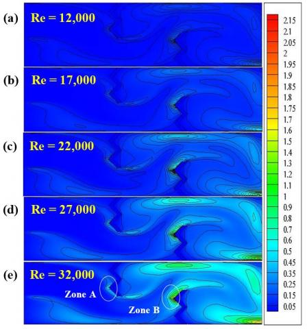
The study also proves the effect of Re on k values. According to Figure 4, the k values are low across the entire channel stream for low Re values. When the Re improves, different areas from the channel appear with average energy values. The first area is located behind the left wall of the channel, where the k value is about 0.4 m2/s2. The second area is small in size, located on the second sharp front head of the first WB, where the k value is around 0.6 m2/s2, see zone (A). Also, another small area, however, is situated behind the top edge of the 1 WB, where the k value is estimated at 0.4 m2/s2. The third region occupies the entire space adjacent to the front and upper parts of the top section of the 2 WB. The k value is approximately 1.2 m2/s2, see zone (B). The fourth region is vast, extending from the top of the second WB, near the hot axis (about 0.8 m2/s2) to the right wall (around 0.6 m2s2). The last area is the zone adjacent to the channel exit, where the k value exceeds 1.2 m2s2.
Figure 4. Variations of k with Re
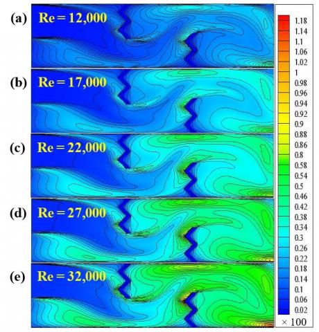
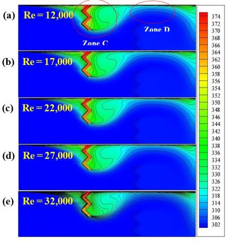
TI fields are also included in this study as shown in Figure 5. The highest TI value was detected in the zone (B) and across the channel exit, for the highest Re value. This intensity is around 100 percent. In Figure 6, there are two different temperature regions. The first region surrounds the first WB, which has a high T (temperature), especially on the back, see zone (C). The second region is located above the second WB, on its rear side, with high TGs (temperature gradients), due to the high Pd and V values in the region, see zone (D). As expected, there is an inversely proportional between the T value and the Re number, while the TG is proportional to the same variable.
Figure 5. Variations of TI with Re
Figure 6. Variations of T with Re
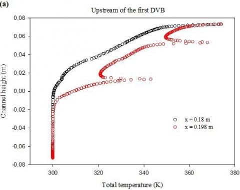
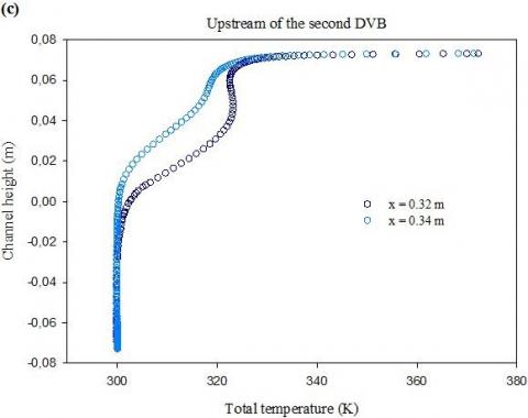
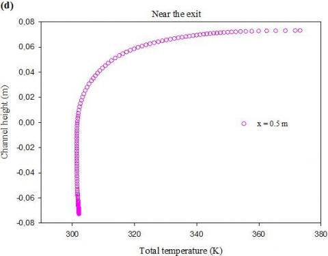
We also studied in detail the T profile variations as shown in Figure 7(a) to 7(d) for different stations of the channel. On the front side of the first WB, precisely at the positions x = 0.18 m and x = 0.198 m, and based on Figure 7(a), the T profiles are elevated, due to their proximity to the left hot surface of the same obstacle. On the right side of the same WB, precisely at the stations x = 0.26 m and x = 0.29 m, and based on Figure 7 (b), the T profiles are very high, due to a decrease in The Pd and V, i.e., low TGs, which resulted in the formation of rotating rings at high Ts. Near the left side of the bottom WB, exactly at the locations x = 0.32 m and x = 0.34 m, and based on Figure 7(c), the T profiles are slightly elevated, due to the presence of an extension in the previous recycling cell to the region. Behind the same WB, precisely at the axial point x = 0.5 m, and based on Figure 7(d), the T profiles are decreasing from the top channel side towards the lower region.
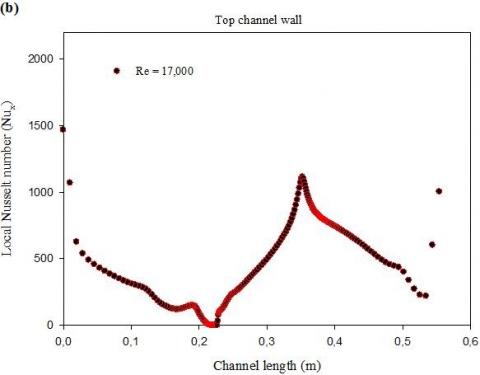
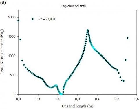
On the other hand, the evolution of the heat-transfer between the hot axis and AHTF was monitored by analyzing the Nux (local Nusselt number) curves for different Re values, as shown in Figures 8(a) and 8(b). Curves analysis highlights three different phases of heat transfer. The first phase runs from the entrance to the channel to the left side of the hot WB.
A decrease in the heat transfer values is reported, especially in front of the fin (first WB), due to the change in the direction of the fluid downward, see zone (A). The second phase extends from the right side of the fin to the front side of the baffle (second WB), see zone (B). A continuous increase in Nux values is given, due to the presence of two cofactors. The presence of recycling cells on the backside of the first WB, and their contact with the hot channel surface allow enhanced heat transfer. Also, the AHTF deflection upward, due to the presence of the lower WB, allows for improved thermal transport, due to the high Pd and V values in the region, especially across the upper gap. The third phase is located to the right of the lower WB, see zone (C). There is a decrease in the values of Nux, due to a deviation in the flow direction, from the upper channel part towards the outlet section located on the lower region.
Figure 7. T profiles for various axial stations, Re = 12 × 103
There are also three main points in the figure. The first point is the place of the first WB. Here, there is no heat transfer. The second point is located just above the bottom WB. Here is the most significant value of the Nux, due to the high TGs in the region. The last point is the end of the third phase, i.e., the corner presented above the channel exit, has the lower value of the heat transfer in the region.
Figure 8. Nux profiles for various Re values
In addition to these changes in thermal transfer, Nux values can be improved by increasing the value of Re number, as in this simulation from 12 × 103 to 3.2 × 10⁴, see Figure 8.
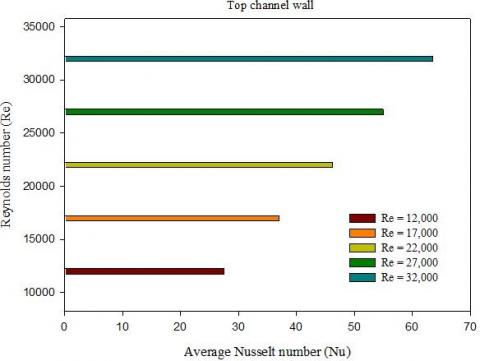
Figure 9 also confirms the effect of Re change on enhancing heat transfer in terms of the Nu (average Nusselt number).
Figure 8. Continued
Figure 9. Nu as a function of Re
In the present analysis, a baffling technique was adopted numerically to optimize the performance of an HEC, using extended solid sections in the form of WB (W-baffle). The results are summarized below:
1) The newly used design allows the flow path to be changed, from straight to wavy. This change in behavior is due to the presence of the WBs.
2) The maximum Pd value is about 2.447 Pa at Re = 12 × 103. This value improves by about 1.016, 2.385, 4.105, and 6.178 times when Re improves to 17, 22, 27, and 32 (× 103), respectively.
3) The best V value is about 5.356 m/s, observed on the upper front side of the bottom WB, and this for Re = 3.2 × 10⁴. That is about 5.102 times the speed of the entrance (Uin).
4) The V value at the exit section reached about 1.812 m/s in the case of the lowest Re value. While, it passed 4.8 m/s in the case of the most significant value of the same variable, i.e., 1.726 to 4.648 times better than the Uin within the limits of Re numbers used.
5) Reverse flows existed behind each WB, in the form of continuous vortices.
6) The highest TI value was detected in the zone (B) and across the channel exit, for the highest Re value. This intensity is around 100 percent.
7) As expected, there is an inversely proportional between the T value and the Re number, while the TG is proportional to the same variable.
8) Nu profile analysis highlighted three different phases of heat transfer:
- The first phase runs from the entrance to the channel to the left side of the hot WB. A decrease in the heat transfer values was reported, especially in front of the fin, due to the change in the direction of the fluid downward.
- The second phase extends from the right side of the fin to the front side of the baffle (second WB). A continuous increase in Nux values was given, due to the presence of two cofactors: (i) the presence of recycling cells on the backside of the first WB, and their contact with the hot channel surface allow enhanced heat transfer. Also, (ii) the AHTF deflection upward, due to the presence of the lower WB, allows for improved thermal transport, due to the high Pd and V values in the region, especially across the upper gap.
- The third phase is located to the right of the lower WB. There was a decrease in the values of Nux, due to a deviation in the flow direction, from the upper channel part towards the outlet section located on the lower region.
9) There are also three main points from the heat transfer profiles:
- The first point is the place of the first WB. Here, there is no heat transfer.
- The second point is located just above the bottom WB. Here is the most significant value of the Nux, due to the high TGs in the region.
- The last point is the end of the third phase, i.e., the corner presented above the channel exit, has the lower value of the heat transfer in the region.
10) In addition to these changes in thermal transfer, Nux values can be improved by increasing the value of Re number, as in this simulation from 12 × 103 to 3.2 × 10⁴. The results also confirm the effect of Re change on enhancing heat transfer in terms of the average Nusselt number.
Some future works related to this type of obstacles:
[1] Berner, C., Durst, F., McEligot D.M. (1984). Flow around baffles. ASME Journal of Heat Transfer, 106: 743-749. https://doi.org/10.1115/1.3246747
[2] Habib, M.A., Attya, A.E., McEligot, D.M. (1988). Calculation of turbulent flow and heat transfer in channels with streamwise-periodic flow. ASME Journal of Turbomachinery, 110: 405-411. https://doi.org/10.1115/1.3262211
[3] Yuan; Z.X., Tao, W.Q., Wang, Q.W. (1998). Numerical prediction for laminar forced convection heat transfer in parallel-plate channels with streamwise-periodic rod disturbances. International Journal for Numerical Methods in Fluids, 28: 1371-1387. https://doi.org/10.1002/(SICI)1097-0363(19981215)28:9<1371::AID-FLD774>3.0.CO;2-A
[4] Cheng, C.H., Huang, W.H. (1991). Numerical prediction for laminar forced convection in parallel-plate channels with transverse fin arrays. International Journal of Heat Mass Transfer, 34(11): 2739-2749. https://doi.org/10.1016/0017-9310(91)90232-4
[5] Hong, Y.J., Hsieh, S.S. (1991). An experimental investigation of heat transfer characteristics for turbulent flow over staggered ribs in a square duct. Experimental Thermal and Fluid Science, 4: 714-722. https://doi.org/10.1016/0894-1777(91)90078-6
[6] Bazdidi-Tehrani, F., Naderi-Abadi, M. (2004). Numerical analysis of laminar heat transfer in entrance region of a horizontal channel with transverse fins. International Communication in Heat and Mass Transfer, 31(2): 211-220. https://doi.org/10.1016/S0735-1933(03)00226-4
[7] Demartini, L.C., Vielmo, H.A., Möller, S.V. (2004). Numeric and experimental analysis of the turbulent flow through a channel with baffle plates. Journal of the Brazilian Society of Mechanical Sciences and Engineering, 26(2): 153-159. https://doi.org/10.1590/S1678-58782004000200006
[8] Li, H., Kottke, V. (1998). Effect of baffle spacing on pressure drop and local heat transfer in staggered tube arrangement. International Journal of Heat and Mass Transfer, 41(10): 1303-1311. https://doi.org/10.1016/S0017-9310(97)00201-9
[9] Mousavi, S.S., Hooman, K. (2006). Heat and fluid flow in entrance region of a channel with staggered baffles. Energy Conversion and Management, 47(15): 2011-2019. https://doi.org/10.1016/j.enconman.2005.12.018
[10] Pirouz, M.M., Farhadi, M., Sedighi, K., Nemati, H., Fattahi, E. (2011). Lattice Boltzmann simulation of conjugate heat transfer in a rectangular channel with wall-mounted obstacles. Scientia Iranica B, 18(2): 213-221. https://doi.org/10.1016/j.scient.2011.03.016
[11] Mokhtari, M., Gerdroodbary, M.B., Yeganeh, R., Fallah, K. (2017). Numerical study of mixed convection heat transfer of various fin arrangements in a horizontal channel. Engineering Science and Technology, 20: 1106-1114. https://doi.org/10.1016/j.jestch.2016.12.007
[12] Webb, B.W., Ramadhyani, S. (1985). Conjugate heat transfer in a channel with staggered ribs. International Journal of Heat Mass Transfer, 28: 1679-1687. https://doi.org/10.1016/0017-9310(85)90142-5
[13] Wen, J., Yang, H., Wang, S., Xue, Y., Tong, X. (2015). Experimental investigation on performance comparison for shell-and-tube heat exchangers with different baffles. International Journal of Heat and Mass Transfer, 84: 990-997. https://doi.org/10.1016/j.ijheatmasstransfer.2014.12.071
[14] Dong, C., Zhou, X.F., Dong, R., Zheng, Y.Q., Chen, Y.P., Hu, G.L., Xu, Y.S., Zhang, Z.G., Guo, W.W. (2017). An analysis of performance on trisection helical baffles heat exchangers with diverse inclination angles and baffle structures. Chemical Engineering Research and Design, 121: 421-430. https://doi.org/10.1016/j.cherd.2017.03.027
[15] Skullong, S., Thianpong, C., Jayranaiwachira, N., Promvonge, P. (2016). Experimental and numerical heat transfer investigation in turbulent square-duct flow through oblique horseshoe baffles. Chemical Engineering and Processing, 99: 58-71. https://doi.org/10.1016/j.cep.2015.11.008
[16] Thianpong, C., Yongsiri, K., Nanan, K., Eiamsa-ard, S. (2012). Thermal performance evaluation of heat exchangers fitted with twisted-ring turbulators. International Communications in Heat and Mass Transfer, 39: 861-868. https://doi.org/10.1016/j.icheatmasstransfer.2012.04.004
[17] Nanan, K., Thianpong, C., Pimsarn, M., Chuwattanakul, V., Eiamsa-ard, S. (2017). Flow and thermal mechanisms in a heat exchanger tube inserted with twisted cross-baffle turbulators. Applied Thermal Engineering, 114: 130-147. https://doi.org/10.1016/j.applthermaleng.2016.11.153
[18] Promvonge, P. (2015). Thermal performance in square-duct heat exchanger with quadruple V-finned twisted tapes. Applied Thermal Engineering, 91: 298-307. https://doi.org/10.1016/j.applthermaleng.2015.08.047
[19] Du, B.C., He, Y.L., Wang, K., Zhu, H.H. (2017). Convective heat transfer of molten salt in the shell-and-tube heat exchanger with segmental baffles. International Journal of Heat and Mass Transfer, 113: 456-465. https://doi.org/10.1016/j.ijheatmasstransfer.2017.05.075
[20] Menni, Y., Chamkha, A.J., Zidani, C., Benyoucef, B. (2020). Baffle orientation and geometry effects on turbulent heat transfer of a constant property incompressible fluid flow inside a rectangular channel. International Journal of Numerical Methods for Heat & Fluid Flow, 30(6): 3027-3052. https://doi.org/10.1108/HFF-12-2018-0718
[21] Menni, Y., Azzi, A., Chamkha, A.J. (2019). Enhancement of convective heat transfer in smooth air channels with wall-mounted obstacles in the flow path. Journal of Thermal Analysis and Calorimetry, 135(4): 1951-1976. https://doi.org/10.1007/s10973-018-7268-x
[22] Menni, Y., Azzi, A., Chamkha, A.J., Harmand, S. (2019). Effect of wall-mounted V-baffle position in a turbulent flow through a channel: Analysis of best configuration for optimal heat transfer. International Journal of Numerical Methods for Heat & Fluid Flow, 29(10): 3908-3937. https://doi.org/10.1108/HFF-06-2018-0270
[23] Menni, Y., Azzi, A., Chamkha, A.J. (2019). Modeling and analysis of solar air channels with attachments of different shapes. International Journal of Numerical Methods for Heat & Fluid Flow, 29(5): 1815-1845. https://doi.org/10.1108/HFF-08-2018-0435
[24] Menni, Y., Chamkha, A.J., Massarotti, N., Ameur, H., Kaid, N., Bensafi, M. (2020). Hydrodynamic and thermal analysis of water, ethylene glycol and water-ethylene glycol as base fluids dispersed by aluminum oxide nano-sized solid particles. International Journal of Numerical Methods for Heat & Fluid Flow, 30(9): 4349-4386. https://doi.org/10.1108/HFF-10-2019-0739
[25] Menni, Y., Ghazvini, M., Ameur, H., Ahmadi, M.H., Sharifpur, M., Sadeghzadeh, M. (2020). Numerical calculations of the thermal-aerodynamic characteristics in a solar duct with multiple V-baffles. Engineering Applications of Computational Fluid Mechanics, 14(1): 1173-1197. https://doi.org/10.1080/19942060.2020.1815586
[26] Menni, Y., Ghazvini, M., Ameur, H., Kim, M., Ahmadi, M.H., Sharifpur, M. (2020). Combination of baffling technique and high thermal conductivity fluids to enhance the overall performances of solar channels. Engineering with Computers, 1-22. https://doi.org/10.1007/s00366-020-01165-x
[27] Menni, Y., Ameur, H., Inc, M. (2020). Improvement of the performance of solar channels by using vortex generators and hydrogen fluid. Journal of Thermal Analysis and Calorimetry, 1-22. https://doi.org/10.1007/s10973-020-10239-3
[28] Menni, Y., Chamkha, A.J., Ameur, H., Sharifpur, M., Inc, M., Ghazvini, M., Ahmadi, M.H. (2021). Enhancement of the turbulent convective heat transfer in channels through the baffling technique and oil/multi-walled carbon nano-tubes nanofluids. Numerical Heat Transfer, Part A: Applications, 79(4): 311-351. https://doi.org/10.1080/10407782.2020.1842846
[29] Menni, Y., Ameur, H., Sharifpur, M., Ahmadi, M.H. (2021). Effects of in-line deflectors on the overall performance of a channel heat exchanger. Engineering Applications of Computational Fluid Mechanics, 15(1), 512-529. https://doi.org/10.1080/19942060.2021.1893820
[30] Menni, Y., Ameur, H., Chamkha, A.J., Inc, M., Almohsen, B. (2020). Heat and mass transfer of oils in baffled and finned ducts. Thermal Science, 24(Suppl. 1): 267-276. https://doi.org/10.2298/TSCI20S1267M
[31] Kolsi, L. (2015). Heat and mass transfer in 3D inclined lid-driven solar distiller. International Journal of Fluid Mechanics & Thermal Sciences, 1(3): 72-82. https://doi.org/10.11648/j.ijfmts.20150103.15
[32] Rashad, A.M. (2017). Impact of anisotropic slip on transient three dimensional MHD flow of ferrofluid over an inclined radiate stretching surface. Journal of the Egyptian Mathematical Society, 25(2): 230-237. https://doi.org/10.1016/j.joems.2016.12.001
[33] Ghalambaz, M., Chamkha, A.J., Wen, D. (2019). Natural convective flow and heat transfer of nano-encapsulated phase change materials (NEPCMs) in a cavity. International Journal of Heat and Mass Transfer, 138: 738-749. https://doi.org/10.1016/j.ijheatmasstransfer.2019.04.037
[34] Ismael, M.A. (2011). Natural convection in a wavy porous enclosure heated by an internal circular cylinder. Al-Qadisiyah Journal for Engineering Sciences, 4(3): 204-220. http://qu.edu.iq/journaleng/index.php/JQES/article/view/218.
[35] Selimefendigil, F. (2019). Mixed convection in a lid-driven cavity filled with single and multiple-walled carbon nanotubes nanofluid having an inner elliptic obstacle. Propulsion and Power Research, 8(2): 128-137. https://doi.org/10.1016/j.jppr.2019.01.007
[36] Ashham, M.A., Raheemah, S.H., Salman, K. (2019). Numerical investigation on enhancement of heat transfer using rod inserts in single pipe heat exchanger. Journal of Mechanical Engineering and Sciences, 13(4): 6112-6124. https://doi.org/10.15282/jmes.13.4.2019.24.0480
[37] Alsabery, A.I., Selimefendigil, F., Hashim, I., Chamkha, A.J., Ghalambaz, M. (2019). Fluid-structure interaction analysis of entropy generation and mixed convection inside a cavity with flexible right wall and heated rotating cylinder. International Journal of Heat and Mass Transfer, 140: 331-345. https://doi.org/10.1016/j.ijheatmasstransfer.2019.06.003
[38] Hajjar, A., Mehryan, S.A.M., Ghalambaz, M. (2020). Time periodic natural convection heat transfer in a nano-encapsulated phase-change suspension. International Journal of Mechanical Sciences, 166: 105243. https://doi.org/10.1016/j.ijmecsci.2019.105243
[39] Kolsi, L. (2016). MHD natural convection and entropy generation in a 3d lid-driven cavity. Frontiers in Heat and Mass Transfer, 7(1): 7-26. http://dx.doi.org/10.5098/hmt.7.26
[40] Rashad, A.M. (2014). Natural convection boundary layer flow along a sphere embedded in a porous medium filled with a nanofluid. Latin American Applied Research, 44(2): 149-157.
[41] Ismael, M.A., AI-Rabeh, R.H. (2010). A new measuring criterion of the performance of the electromagnetic flow meter. Basrah Journal for Engineering Science, 10(1): 133-144.
[42] Selimefendigil, F. (2015). Numerical investigation and recurrence plot analysis of pulsating magneto hydrodynamic mixed convection over a backward facing step. Nonlinear Analysis, 20(3): 428-446. https://doi.org/10.15388/NA.2015.3.8
[43] Ghalambaz, M., Groşan, T., Pop, I. (2019). Mixed convection boundary layer flow and heat transfer over a vertical plate embedded in a porous medium filled with a suspension of nano-encapsulated phase change materials. Journal of Molecular Liquids, 293: 111432. https://doi.org/10.1016/j.molliq.2019.111432
[44] Mehryan S.A.M., Izadpanahi E., Ghalambaz M., Chamkha A.J. (2019). Mixed convection flow caused by an oscillating cylinder in a square cavity filled with Cu-Al2O3/water hybrid nanofluid. Journal of Thermal Analysis and Calorimetry, 137(3): 965-982. https://doi.org/10.1007/s10973-019-08012-2
[45] Azmi, W.H., Zainon, S.N.M., Hamid, K.A., Mamat, R. (2019). A review on thermo-physical properties and heat transfer applications of single and hybrid metal oxide nanofluids. Journal of Mechanical Engineering and Sciences, 13(2): 5182-5211. https://doi.org/10.15282/jmes.13.2.2019.28.0425
[46] Menni, Y., Chamkha, A.J., Ameur, H. (2020). Advances of nanofluids in heat exchangers - a review. Heat Transfer, 49(8): 4321-4349. https://doi.org/10.1002/htj.21829
[47] Menni, Y., Chamkha, A.J., Lorenzini, G., Kaid, N., Ameur, H., Bensafi, M. (2019). Advances of nanofluids in solar collectors - a review of numerical studies. Mathematical Modelling of Engineering Problems, 6(3): 415-427. https://doi.org/10.18280/mmep.060313
[48] Menni, Y., Chamkha, A.J., Zidani, C., Benyoucef, B. (2019). Numerical analysis of heat and nanofluid mass transfer in a channel with detached and attached baffle plates. Mathematical Modelling of Engineering Problems, 6(1): 52-60. https://doi.org/10.18280/mmep.060107
[49] Menni, Y., Chamkha, A.J., Zidani, C., Benyoucef, B. (2019). Heat and nanofluid transfer through baffled channels in different outlet models. Mathematical Modelling of Engineering Problems, 6(1): 21-28. https://doi.org/10.18280/mmep.060103
[50] Menni, Y., Chamkha, A.J., Azzi, A. (2019). Nanofluid flow in complex geometries - a review. Journal of Nanofluids, 8(5): 893-916. https://doi.org/10.1166/jon.2019.1663
[51] Menni, Y., Chamkha, A.J., Azzi, A. (2019). Nanofluid transport in porous media - a review. Special Topics & Reviews in Porous Media, 10(1): 49-64. https://doi.org/10.1615/SpecialTopicsRevPorousMedia.2018027168
[52] Maouedj, R., Menni, Y., Inc, M., Chu, Y.M., Ameur, H., Lorenzini, G. (2021). Simulating the turbulent hydrothermal behavior of Oil/MWCNT nanofluid in a solar channel heat exchanger equipped with vortex generators. Computer Modeling in Engineering & Sciences, 126(3): 855-889. https://doi.org/10.32604/cmes.2021.014524
[53] Mahammedi, A., Ameur, H., Menni, Y. (2021). Investigation of the convective heat transfer and friction factor of magnetic Ni nanofluids within cylindrical pipes, International Journal of Thermofluid Science and Technology, 8(1). https://doi.org/10.36963/IJTST.2021080101
[54] Mahammedi, A., Ameur, H., Menni, Y., Medjahed, D.M. (2021). Numerical study of turbulent flows and convective heat transfer of Al2O3-water nanofluids in a circular tube. Journal of Advanced Research in Fluid Mechanics and Thermal Sciences, 77(2): 1-12. https://doi.org/10.37934/arfmts.77.2.112
[55] Menni, Y., Chamkha, A.J., Makinde, O.D. (2020). Turbulent heat transfer characteristics of a W-baffled channel flow - heat transfer aspect. Defect and Diffusion Forum, 401: 117-130. https://doi.org/10.4028/www.scientific.net/DDF.401.117
[56] Menni, Y., Chamkha, A.J., Ameur, H., Inc, M. (2020). Enhancement of the hydrodynamic characteristics in shell-and-tube heat exchangers by using W-baffle vortex generators. Periodica Polytechnica Mechanical Engineering, 64(3): 212-223. https://doi.org/10.3311/PPme.15493