Afia Mubassira Islam* | Emraul Islam Emon | Anis Ahmed
© 2020 IIETA. This article is published by IIETA and is licensed under the CC BY 4.0 license (http://creativecommons.org/licenses/by/4.0/).
OPEN ACCESS
In this study, we have proposed a metamaterial loaded microstrip patch antenna for the sub-6 GHz range to operate in the Unlicensed National Information Infrastructure (U-NII) band. The Proposed Microstrip Patch Antenna (PMPA) has a U-shaped patch and an array of Complementary Split Ring Resonators (CSRR) in the ground plane. By adding a slot in the middle, the rectangular patch becomes a U-shaped one which is responsible for the enhancement of antenna bandwidth and gain. Our antenna provides a bandwidth of 392 MHz which is about 2.7 times larger compared to that of a Conventional Microstrip Patch Antenna (CMPA) of the same dimension. The maximum gain of our antenna is found 6.56 dB which is around 2 dB higher than that of the conventional one (4.72 dB). Due to the addition of the CSRR array in the ground plane, an improved impedance matching of 50 ohms has been achieved. The operating frequency range of the PMPA is from 5.525 to 5.917 GHz which can be used for 5G applications such as Wi-fi, Wi-Max, and IoT devices in the U-NII band.
5G wireless technology, CSRR array, microstrip patch antennas, U-NII band
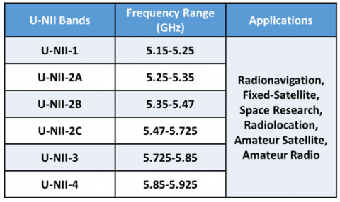
Over the last few decades, there has been tremendous growth in the wireless communication sector. The 5G is the emerging next generation of wireless technology in this field. This generation offers a peak data rate of 20 Gbps which is twenty times faster than 4G [1, 2]. 5G technology is a must needed tool in the implementation of high-speed Wi-Fi, smart city, smart homes, GPS technology, real-time weather updates, various healthcare, and security service as shown in Figure 1. There are a large number of licensed 5G bands in sub-6 GHz and in the millimeter-wave range which are currently being used extensively. Apart from these bands, there are a number of bands in the Unlicensed National Information Infrastructure (U-NII) spectrum such as 5.15-5.35 GHz (U-NII-1, U-NII-2A), 5.47-5.725 GHz (U-NII-2C) that can also be used to solve the problems of high network traffic in heavily congested areas as illustrated in Figure 2 [3, 4]. The Unlicensed spectrum does not require an expensive license and this band needs to be utilized by general people to provide inexpensive internet service [5]. For successful implementation of 5G technology in both types of bands, wideband, high gain, and lightweight antennas are needed [6].
Microstrip Patch Antennas (MPAs) have been found to be suitable for the 5 GHz band as they ensure low fabrication cost, smaller size, and weight reduction. However, these antennas have narrow bandwidth and low gain/directivity [6]. To overcome these problems antennas with new types of patches such as Sierpinski-fractal geometry and Compact folded patch have been developed [7, 8]. Numerous types of slots such as M-slot, T-slot, E-slot, and L-slot are being investigated to increase the gain and bandwidth [9]. For these modifications in the MPA, the bandwidth has been increased but the gain does not improve remarkably. The characteristics of these slot-loaded antennas deteriorate greatly when the size is minimized. As a possible solution to these problems, researchers have been working with metamaterial loaded MPA.
Figure 1. Applications of 5G Wireless Network
In the late 2000s, the metamaterial structures have begun to appear in antenna design to improve the characteristics in terms of gain, return loss, efficiency, etc. [10]. During the design of MPA, the Split Ring Resonators (SRR) have been introduced in the patch, in the substrate, and in the ground plane [11-13]. Some researchers have also studied the characteristics of MPA by incorporating metamaterials in the antenna feedline [11]. Complimentary Split Ring Resonators (CSRR) array has also been used in the ground plane of antennas [14]. These antennas show enhanced characteristics and better efficiency than that of a conventional antenna of the same size.
In this paper, a microstrip patch antenna with a slot in the patch and an array of Complementary Split Ring Resonators (CSRR) in the ground has been investigated. The Coaxial feeding technique has been used in the antenna to provide 50 ohms impedance matching. The Proposed Microstrip Patch Antenna (PMPA) is 5cm × 5cm in size. The slot is positioned in the middle of the patch to make it a U-shaped structure. The introduction of the slot and the CSRR array together ensure enhancement of the gain and the impedance bandwidth of our proposed antenna. The return loss of our proposed antenna has increased from -13 dB to -56 dB as impedance matching can be achieved easily due to the effect of the CSRR array. The focus has been given to designing the patch size for the resonant frequency of 5.6 GHz so that our antenna can be used in the U-NII-2C band. From the simulation with CST microwave studio, it is found that our PMPA has an operating frequency range from 5.525 to 5.917 GHz and is suitable for applications such as Amateur-satellite service, Radiolocation, Wireless modems for computers and cellphones, and so forth.
Figure 2. Spectrum and applications of 5 GHz Unlicensed National Information Infrastructure (U-NII) band
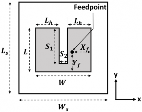
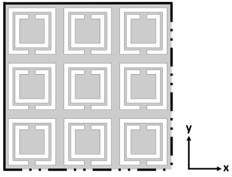
The geometry of our Proposed Microstrip Patch Antenna (PMPA) is shown in Figure 3. The PMPA has a U-shaped copper patch on a square FR-4 substrate and a ground plane covered with Complementary Split Ring Resonator (CSRR) array. The shaded region in Figure 3 represents the copper layer and the white area represents the substrate. The front side of the antenna is shown in Figure 3(a) where Ls is the length and Ws is the width of the FR-4 substrate. The patch having length L and width W is placed in the middle of the substrate. The length and the width Ws of the substrate are 2.6 times and 2 times the length and width of the patch, respectively. That means $L s=2.6 L$ and $W s=2 W$. A slot of $S_{1} \times S_{2}$ is positioned from the upper side towards the lower side of the patch along the middle line. Thus, the shape of the patch becomes a U-shaped one (see Figure 3 (a)). A truncated view of the metamaterial loaded ground plane of the PMPA is shown in Figure 3(b) where the arrangement of the CSRR unit cells is seen. The co-axial technique has been used in the antenna for feeding the patch as can be found in Figure 4. The detailed design process of the PMPA is outlined in the Research Methodology section.
The PMPA has been designed to have a U-NII-2C band to utilize the advantages of the unlicensed spectrum. The final structure of our proposed antenna has been found after three stages of design:
i) Design Stage 1: A CMPA has been designed with a rectangular patch and full ground plane.
ii) Design Stage 2: The rectangular patch of CMPA has been modified by introducing a slot to get a U-shaped patch structure.
iii) Design Stage 3: A CSRR unit cell has been designed. The ground plane has been modified with an array of 19×19 CSRR unit cells.
(a)
(b)
Figure 3. (a) Front view of the proposed Metamaterial loaded MPA, (b) Truncated view of the ground plane with CSRR array
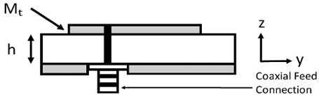
Figure 4. Side view of the PMPA showing coaxial feed connection
In the first stage of the design process, a conventional microstrip patch antenna has been designed for the resonant frequency of $f r$= 5.6 GHz using the Transmission-line model equations given below. These equations are used to determine the initial dimensions of the patch at the resonant frequency of the antenna [15]. At first, the patch width, W is determined by the following expression (for $W / h>>1$).
$W=\frac{C}{2 \times f_{r}} \times \sqrt{\frac{2}{\epsilon_{r}+1}}$ (1)
For calculating the patch length $L$, the effective dielectric constant, $\epsilon_{\text {reff}},$ and effective length, $L_{\text {eff}}$ are needed. The length of the patch changes due to the fringing effect of the field. Therefore, a correction factor $\Delta L$ is introduced in the patch length equation as can be seen below:
$L=L_{e f f}-2 \Delta L$ (2)
where, the effective length, $L_{e f f}$ in terms of $\epsilon_{r e f f}$ is expressed as:
$L_{e f f}=\frac{C}{2 \times f_{r} \times \sqrt{\epsilon_{r_{e f f}}}}$ (3)
The length correction factor $\Delta L$ can be approximated by the expression:
$\Delta L=0.412 h \times \frac{\left(\epsilon_{\text {reff}}+0.3\right)\left(\frac{W}{h}+0.264\right)}{\left(\epsilon_{\text {reff}}-0.258\right)\left(\frac{W}{h}+0.8\right)}$ (4)
And the effective dielectric constant, $\epsilon_{\text {reff}}$ is given by:
$\varepsilon_{r_{e f f}}=\frac{\varepsilon_{r}+1}{2}+\left[\frac{\varepsilon_{r}-1}{2}\right]\left[\left(1+\frac{12 h}{W}\right)\right]^{-\frac{1}{2}}$ (5)
The substrate material for the antenna is considered FR-4 which has a dielectric constant, $\epsilon_{r}$= 4.3, and a loss tangent of 0.002. After calculating the initial antenna dimensions, it is seen that the initial patch dimensions do not show a resonant peak at the required frequency in simulation. As the resonant frequency varies with the dimensions of the patch, the proper dimensions of the patch have been found by optimization with CST Microwave Studio to achieve the desired resonant frequency.
The coaxial feeding technique has been selected for our PMPA as it has given better results than the Inset feeding technique during the optimization process. This technique has shown satisfactory impedance matching at a number of different locations on the patch. As a result, the coaxial feeding technique provides flexibility for choosing the feeding location $\left(X_{f}, Y_{f}\right)$ on the patch. In order to get better antenna characteristics, the distances $X_{f}=7.14 \mathrm{~mm}$ and $Y_{f}=9.21 \mathrm{~mm}$ have been found suitable as shown in Figure 3(a). The coaxial feed connection can be seen in Figure 4 where the side view of the PMPA is shown. In this figure, the copper patch thickness and the substrate height are represented by $M_{t}$ and h, respectively.
In the second stage, a slot has been introduced in the patch of the Conventional MPA (CMPA) making it a U-shaped one as can be seen in Figure 3(a) to achieve better bandwidth characteristics. The antenna bandwidth varies with the change of the slot dimensions [16]. The increment of bandwidth has been observed by varying the slot-length $S_{1}$ and slot-width $S_{2}$ in the range of $10 \mathrm{~mm}$ to $20 \mathrm{~mm}$ and $0.5 \mathrm{~mm}$ to $2.5 \mathrm{~mm}$, respectively. For $S_{1}=15.5 \mathrm{~mm}$ and $S_{2}=1.7 \mathrm{~mm},$ the bandwidth of our antenna becomes the highest. Although better bandwidth is achieved with the U-shaped structure of the patch, the return loss characteristic is not satisfactory enough. To compensate for this, an array of Complementary Split Ring Resonators (CSRR) has been introduced in the ground plane of the PMPA in the final design stage. The structure of the CSRR unit cell array has been designed to utilize the negative refractive index property of left-handed metamaterial at the resonant frequency. The CSRR array in the ground plane induces a magnetic field that results in negative permeability [17]. This means that the group and phase velocity of the electromagnetic wave are in opposite direction [18]. Thus the propagation direction of the wave is reversed and it is opposite to the energy flow direction resulting in a reversed Doppler shift. As a result, the return loss, S11 improves and the Voltage Standing Wave Ratio (VSWR) decreases. Therefore, the introduction of a CSRR array in the ground plane can enhance impedance matching characteristics.
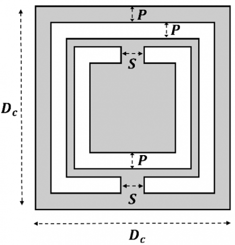
Initially, a single CSRR unit cell has been designed to have a negative refractive index effect in the operating frequency band. The structural view of the planar-square CSRR unit cell is illustrated in Figure 5. The length(/width) of the square unit cell is denoted by $D_{C}$. Generally, the length, $D_{C}$ is kept less than the resonant wavelength of the unit cell [18]. By optimizing the dimensions of the square CSRR unit cell, length, $D_{c}$ of the unit cell is found to be 2.5 mm for the resonant wavelength of 52.91 mm corresponding to $f_{r}$=5.6 GHz [19, 20]. The ring width, P and gap,S of the unit cell have been kept 0.2 mm. The ring width and gaps of all the unit cells in the ground plane induce series capacitance that dominates resonant characteristics of the whole antenna [19]. Finally, the unit cell has been extended to make a 19×19 CSRR array that covers the whole ground plane.
The final structure of our proposed antenna has been simulated by CST Microwave Studio and the optimized values of the dimensions are shown in Table 1.
Table 1. Optimized dimensions of the PMPA
|
Parameter Name |
Parameter Symbol |
Parameter Value (mm) |
|
Resonance Frequency |
$f_{r}$ |
5.67 GHz |
|
Wavelength |
$\lambda$ |
52.91 |
|
Substrate length |
$L_{S}$ |
$50.19(\approx 0.95 \lambda)$ |
|
Substrate width |
$W_{s}$ |
$50.32(\approx 0.95 \lambda)$ |
|
Substrate height |
h |
$1.6(\approx 0.03 \lambda)$ |
|
Patch length |
L |
$19(\approx 0.36 \lambda)$ |
|
Patch width |
W |
$25(\approx 0.47 \lambda)$ |
|
Patch thickness |
$M_{t}$ |
$0.035(\approx 0.0007 \lambda)$ |
|
Feedpoint distance in the horizontal plane |
$X_{f}$ |
$7.14(\approx 0.13 \lambda)$ |
|
Feedpoint distance in the vertical plane |
$Y_{f}$ |
$9.21(\approx 0.17 \lambda)$ |
|
Width of the first and second section of the patch |
$L_{h}$ |
$11.65(\approx 0.22 \lambda)$ |
|
Slot Length |
$S_{1}$ |
$15.5(\approx 0.29 \lambda)$ |
|
Slot Width |
$S_{2}$ |
$1.7 \quad(\approx 0.03 \lambda)$ |
Figure 5. Structure of a square CSRR unit cell
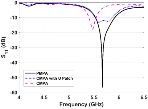
As explained in the previous section, a rectangular patch of a conventional MPA is first modified into a U-shaped patch and the ground plane is then converted into a metamaterial plane by adding a CSRR array. In this section, the simulated results of our proposed MPA and also the conventional MPAs (with and without U patch) are presented. The simulated return loss patterns for the three stages of the design are shown in Figure 6. It is seen from this figure that the highest return loss magnitude of about -56.59 dB at 5.67 GHz is found for our PMPA (solid curve). The CMPA with U patch (dotted curve) shows little impedance matching with increased bandwidth compared to that of the CMPA. The PMPA shows a resonant peak at 5.67 GHz instead of 5.6 GHz which was the target of our design. From the figure, it is found that the bandwidth of the CMPA is about 144 MHz (dashed curve). Whereas the bandwidth of our PMPA has been found to be 392 MHz (5.525-5.917 GHz) which is about 2.7 times greater than that of the CMPA.
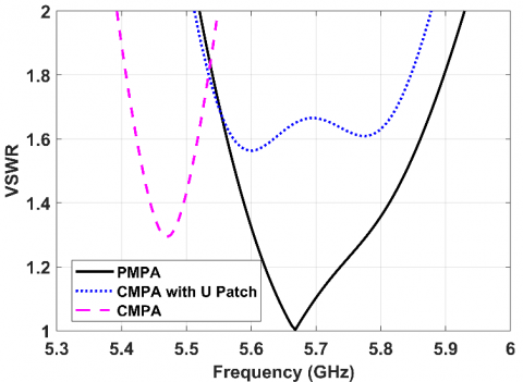
The Voltage Standing Wave Ratio (VSWR) characteristics of three design stages are shown in Figure 7. Our PMPA shows a VSWR of almost unity at 5.67 GHz and less than 2 in the whole operating frequency range. It is seen that the VSWR of the CMPA with U patch is always greater than around 1.65 for the operating frequency of interest. Thus, PMPA with CSRR array provides better impedance matching. The VSWR characteristics of the CMPA is outside the frequency band of our concern.
In Figure 8, the variations of gain of the MPAs with respect to frequency are depicted. It is found that the gain of the CMPA at the starting of the operating frequency band is 4.5 dB which decreases further up to 2.8 dB at the end of the band (dashed curve). It can be seen from the figure that the gain is greater than 5 dB throughout the operating frequency band for PMPA (solid curve). The gain of the CMPA with U patch also provides a gain of more than 5 dB in the operating frequency band. The increment of gain is due to the U-patch as the CMPA shows less gain than the CMPA with U patch and the PMPA. The highest gain of the PMPA has been obtained 6.56 dB (5.67 GHz) whereas the gain for the CMPA is 4.72 dB (5.47 GHz). It is found that the gain increases by almost 2 dB for the PMPA.
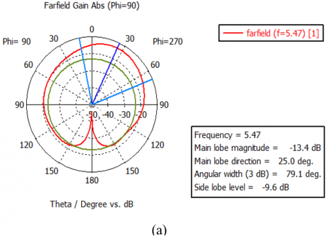
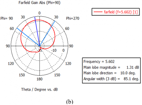
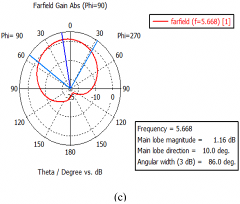
Figure 9 shows farfield radiation patterns for three design stages. The pattern for the CMPA is exhibited in Figure 9(a). This pattern exhibits a large side lobe. The farfield radiation patterns of the PMPA and CMPA with U patch are portrayed in Figure 9(b) and 9(c), respectively. Both radiation patterns are hemispherical which agrees well with the theory of microstrip patch antenna. The main lobe directions for Figure 9(b) and 9(c) are found at 10.0 deg. It is seen that after the introduction of the slot the sidelobes are completely eliminated. The gain and directivity are found 6.560 dB and 9.115 dB, respectively in the radiation pattern of the PMPA.
Figure 6. Frequency responses of return loss for the MPAs (GP: ground plane)
Figure 7. VSWR characteristics with respect to frequency for the MPAs
Figure 8. Gain vs frequency response for the MPAs
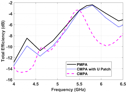
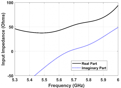
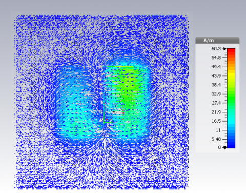
The total efficiency variations of the MPAs are depicted in Figure 10. It is seen that the PMPA has better efficiency characteristics in the operating band. The input impedance characteristic is plotted with respect to the frequency in Figure 11 for the PMPA. The imaginary part is close to zero in the frequency region of interest and the real part of the impedance is close to 50 Ohm which reflects good impedance matching. A snapshot of the animated surface current distribution of the proposed MPA is displayed in Figure 12. The current distribution is found highest in the U- shaped patch. When the current distribution of one arm is highest, the other arm has a slightly lower current distribution which oscillates continuously.
Figure 9. Farfield radiation pattern for the (a) Conventional MPA with no slot, (b) MPA with slot and plain ground plane, (c) Proposed MPA
Figure 10. Total efficiency characteristics with respect to frequency for the MPAs
Figure 11. Input impedance plot for the PMPA with respect to frequency
Figure 12. Simulated surface current distributions of the proposed PMPA
In Table 2 the main antenna parameters for three design stages are presented. It can be seen from this table that the PMPA exhibits superior characteristics in terms of performance than the other two design stages. The S11 of our PMPA is the most enhanced parameter out of all three models. The gain of our PMPA has increased by almost 2 dB from the conventional MPA. The bandwidth of the CMPA is found 144 MHz while much increased bandwidth has been found for the PMPA (392 MHz).
Table 2. Comparison of three design stages
|
Parameters |
CMPA |
CMPA with U patch |
PMPA with CSRR array in ground plane |
|
Operating Freq. Range (GHz) |
5.40-5.544 |
5.519-5.867 |
5.525-5.917 |
|
Bandwidth (MHz) |
144 |
348 |
392 |
|
Return Loss (dB) |
-18 |
-13.16 |
-56.59 |
|
Gain (dB) |
4.72 |
6.60 |
6.56 |
|
VSWR @ Resonant Freq. (GHz) |
1.29 @ 5.47 |
1.56 @ 5.6 |
1.003 @ 5.67 |
The U-shaped patch achieved by the introduction of a slot in the patch has contributed to broadening the bandwidth but the return loss characteristic is not satisfactory. Thus, with only the slot, the antenna is not much efficient for practical application as the impedance matching is poor. The return loss characteristic has improved a lot due to the application of Left-Handed Material (LHM) in the ground plane by the use of CSRR array. LHMs have negative permittivity and negative permeability, thereby a negative refractive index [21]. A negative refractive index induces a backward-wave which produces better radiation from the antenna resulting in low loss [19, 22, 23]. From this study, we have found that the use of a slot and a CSRR array in the ground plane together ensure much better performance of a microstrip patch antenna.
A metamaterial loaded microstrip patch antenna has been proposed for use in the 5G Unlicensed National Information Infrastructure band. By introducing a slot in the middle of a rectangular patch, the structure of the patch becomes a U-shaped one which is responsible for increasing the gain and the bandwidth. A bandwidth of 392 MHz (5.525-5.917 GHz) has been achieved in our PMPA. The bandwidth of our antenna has increased almost 2.7 times than the conventional one. Throughout the whole operating band, the gain of our proposed antenna has been found higher than 5 dB. The maximum gain of our antenna is 6.56 dB which is 2 dB higher than the conventional antenna. Better impedance matching is achieved by adding a CSRR array in the ground plane. The obtained return loss magnitude is-56.59 dB considering a 50 ohms SMA connector in the port. The PMPA exhibits a VSWR less than 2 dB in the operating frequency band. The radiation patterns of our PMPA are found very close to the ideal one without any side lobe. The designed PMPA has high gain, wide bandwidth, and is suitable for 5G wireless applications in the U-NII band such as Wi-fi, Wi-Max, and IoT devices.
The research work has been carried out at Microwave and Optical Fiber Communication Laboratory at the Department of Electrical and Electronic Engineering, University of Dhaka, Bangladesh funded by the Higher Education Quality Enhancement Project (HEQEP).
|
C |
velocity of light, ms-1 |
|
PMPA |
Proposed Microstrip Patch Antenna |
|
CMPA |
Conventional Microstrip Patch Antenna |
|
Greek symbols |
|
|
ɛ |
dimensionless dielectric constant |
|
λ |
wavelength, nm |
|
Subscripts |
|
|
r |
resonance |
|
s |
substrate |
|
eff |
effective |
|
f |
feed point |
[1] "Roadmap," IEEE Future Networks. https://futurenetworks.ieee.org/roadmap, accessed on Jan. 11, 2020.
[2] Everything You Need to Know About 5G. IEEE Spectrum: Technology, Engineering, and Science News, 2020. https://spectrum.ieee.org/video/telecom/wireless/everything-you-need-to-know-about-5g, accessed on 26 Feb. 2020.
[3] Zhang, R., Wang, M., Cai, L.X., Zheng, Z., Shen, X., Xie, L.L. (2015). LTE unlicensed: The future of spectrum aggregation for cellular networks. IEEE Wireless Communications, 22(3): 150-159. https://doi.org/10.1109/MWC.2015.7143339
[4] Xu, S., Li, Y., Gao, Y., Liu, Y., Gacanin, H. (2018). Opportunistic coexistence of lte and WIFI for future 5G system: Experimental performance evaluation and analysis. IEEE Access, 6: 8725-8741. https://doi.org/10.1109/ACCESS.2017.2787783
[5] Sun, H., Fang, Z., Liu, Q., Lu, Z., Zhu, T. (2017). Enabling LTE and WIFI coexisting in 5 GHz for efficient spectrum utilization. Journal of Computer Networks and Communications, 2017: 1-17. https://doi.org/10.1155/2017/5156164
[6] Abirami, M. (2017). A review of patch antenna design for 5G. 2017 IEEE International Conference on Electrical, Instrumentation and Communication Engineering (ICEICE), Karur, pp. 1-3. https://doi.org/10.1109/ICEICE.2017.8191842
[7] Mahlaoui, Z., Latif, A., Hussaini, A.S., Elfergani, I.T.E., Ali, A., Mirza, F., Abd-Alhameed, R.A. (2015). Design of a Sierpinski patch antenna around 2.4 GHz/5GHz for WiFi (IEEE 802.11n) applications. 2015 Internet Technologies and Applications (ITA), Wrexham, pp. 472-474. https://doi.org/10.1109/ITechA.2015.7317450
[8] Jolani, F., Dadgarpour, A., Hassani, H. (2008). Compact M-slot folded patch antenna for WLAN. Progress in Electromagnetics Research Letters, 3: 35-42. https://doi.org/10.2528/pierl08012801
[9] Sharma, M.D., Katariya, A., Meena, R.S. (2012). E shaped patch microstrip antenna for wlan application using probe feed and aperture feed. 2012 International Conference on Communi cation Systems and Network Technologies, Rajkot, pp. 66-70. https://doi.org/10.1109/CSNT.2012.24
[10] Yamaguchi, K., Yoshitomi, K., Kanaya, H. (2016). Development of 5GHz circularly polarized slot antenna. 2016 IEEE 5th Asia-Pacific Conference on Antennas and Propagation (APCAP), Kaohsiung, pp. 59-60. https://doi.org/10.1109/APCAP.2016.7843098
[11] Chen, B., Jiao, Y., Ren, F., Zhang, F. (2011). Dual wideband open slot antenna with a band-rejected slit for 3.5/5.5GHz WiMAX and 5.2/5.8GHz WLAN applications. 2011 4th IEEE International Symposium on Microwave, Antenna, Propagation and EMC Technologies for Wireless Communications, Beijing, pp. 113-115. https://doi.org/10.1109/MAPE.2011.6156245
[12] Krzysztofik, W.J., Cao, T.N. (2019). Metamaterials in application to improve antenna parameters. Metamaterials and Metasurfaces. https://doi.org/10.5772/intechopen.80636
[13] Liu, Y., Guo, X., Gu, S., Zhao, X. (2013). Zero index metamaterial for designing high-gain patch antenna. International Journal of Antennas and Propagation, 2013: 1-12. https://doi.org/10.1155/2013/215681
[14] Manikandan, R., Jawahar, P.K., Rao, P.H. (2018). Low sidelobe level CSRR loaded weighted array antenna. in IEEE Transactions on Antennas and Propagation, 66(12): 6893-6905. https://doi.org/10.1109/TAP.2018.2870335
[15] Balanis, C.A. (2016). Antenna Theory: Analysis and Design. Hoboken, NJ: Wiley, 2016.
[16] Darimireddy, N., Reddy, R., Prasad, A. (2015). Design of U-shaped patch antenna for UWB applications. In IEEE Technically Co-Sponsored National Conference on "Emerging Trends in Signal Processing and Communication Engineering” (ESPACE), AITAM, Tekkali, 2015.
[17] Phan, D.T., Phan, H.L., Nguyen, T.Q.H. (2016). A miniaturization of microstrip antenna using negative permittivity metamaterial based on CSRR loaded ground for WLAN applications. Journal of Science and Technology, 54(6): 689-697. https://doi.org/10.15625/0866708X/54/6/8375
[18] Gupta, V., Sahoo, P. (2014). Performance improvement of microstrip patch antenna using left-handed metamaterial. International Journal of Research in Electronics and Communication Technology, 1(1): 46-49.
[19] Md. Mahmud, M., Islam, M.T., Misran, N., Singh, M.J., Mat, K. (2017). A negative index metamaterial to enhance the performance of miniaturized UWB antenna for microwave imaging applications. Applied Sciences, 7(11): 1149. https://doi.org/10.3390/app7111149
[20] Elsdon, M., Yurduseven, O., Dai, X. (2017). Wideband metamaterial solar cell antenna for 5 GHz Wi-Fi communication. Progress in Electromagnetics Research C, 71: 123-131. https://doi.org/10.2528/PIERC16110302
[21] Zhou, J., Koschny, T., Zhang, L., Tuttle, G., Soukoulis, C.M. (2006). Experimental demonstration of negative index of refraction. Appl. Phys. Lett., 88(2): 221103. https://doi.org/10.1063/1.2208264
[22] Li, L.W., Li, Y.N., Yeo, T.S., Mosig, J.R., Martin, O.J.F. (2010). A broadband and high-gain metamaterial microstrip antenna. Appl. Phys. Lett., 96(16): 164101. https://doi.org/10.1063/1.3396984
[23] Singh, H.S., Pandey, G.K., Meshram, M.K., Bharti, P.K. (2014). Metamaterial-based UWB antenna. Electronics Letters, 50(18): 1266-1268. https://doi.org/10.1049/el.2014.2366