Manoj Kumar* | Rasmikanti Biswal | Ajay K. Gupta | Suraj K. Behera | Ranjit K. Sahoo
© 2020 IIETA. This article is published by IIETA and is licensed under the CC BY 4.0 license (http://creativecommons.org/licenses/by/4.0/).
OPEN ACCESS
In this study, the two-dimensional, incompressible numerical analysis is carried out to understand the turbulent fluid flow physics and thermal characteristics of a dual jet consisting of a wall jet and a parallel offset jet using standard k-ε RNG turbulence model. The study is carried out to compare the flow and thermal features of the dual jet for an offset ratio of 3, 7 and 9 at different Reynolds numbers in the range of 5,000 to 20,000. The results of the flow field and turbulent behavior of a dual jet are illustrated in the form of temperature contours, velocity vectors, streamlines, and turbulent kinetic energy at different Reynolds number and offset ratio. The effect of offset ratio and Reynolds number on recirculation region and intensity of upper and lower vortices are discussed in detail. The velocity variation along the axial and vertical direction are also discussed.
offset dual jet, fluid flow and thermal characteristics, wall heat flux
The turbulent flow is playing a vital role in modern days’ research and academic applications. It has various applications in industries as well as the devices which contains flow deflection, cooling of gas turbines, combustion chamber, an automobile demister, mixing process in boiler combustion chambers, heat exchangers, engine carburetor systems, aircrafts ventilation, air-conditioning systems, etc. [1-3]. The turbulent jet is mainly classified into a free jet, wall jet, offset jet, dual jet which depends on the placement of jet. A dual jet containing a plane wall jet at the base and a jet with a distance have additional advantages than other jets. If the jet is placed horizontally at the wall is known as wall jet. Also, a jet is placed with some distance from the base is known as offset jet. The wall and offset jet combinedly known as a dual jet.
Rathore and Das [4] conducted a comparative numerical study of flow field analysis and turbulent behavior of wall jet using a low-Reynolds number k-ε model proposed by Launder and Sharma with a standard k-ε model. It was noticed that the Moffatt vortices were occurred in the secondary recirculation region near the wall using a low-Reynolds number modeling approach.
Kumar and das [5] conducted a two-dimensional numerical analysis to compare the momentum flux along the axial direction of a wall jet, dual jet, and offset jet. It is noticed that a similarity profile occurred along the downstream direction. The variation of Reynold stress, pressure variation, turbulence kinetic energy, etc. was compared.
Rao and Das [6] studied the heat transfer characteristics of a wall and offset jet by varying the offset ratio. The constant wall temperature and heat flux boundary condition along with Reynolds number (10000-40000 at Prandtl number of 0.71) were considered in this study.
Mondal et al. [7-9] numerically investigated the interaction between wall jet and offset jet at different velocity ratio (0.78-1.34) for Reynolds number 10000. The height of the wall jet was varied in the range of 0.2 to 2. It is noticed that two counter-rotating vortices occurred for jet height 0.2 whereas a periodic vortex has occurred for higher jet height (greater than 0.3).
Singh et al. [10] studied the heat transfer and fluid flow phenomenon of a dual jet striking on the wavy surface. The amplitude of the wavy surface was varied between 0.1 - 0.7 and has 10 number of cycles. The offset ratio was fixed to be 7. It is observed that an instantaneous pressure drop is obtained in the recirculation zone for the wavy surface.
From the literature review, it is observed that the effect of bottom wall heat flux on flow patterns and thermal behavior of a turbulent dual jet need to be investigated. This work fulfills this literature gap.
In this paper, the effect of wall heat flux on the mixing of fluid of a dual jet consisting of plane wall and jet and parallel offset jet are studied. Dual jet will behave like a wall jet after the combined region where the inlet jets meet in the flow region. The effect of the offset ratio under different Reynolds number is also studied which have a significant effect on the mixing process. For different types of flow domains, temperature distribution will change because of changes in flow characteristics by different parameters like geometry, inlet fluid temperatures. The present results are validated with the experimental results available in the literature.
The paper is systematized as follows: Section 2 discusses the computational domain, boundary conditions, governing equations, numerical issues, and model validation. Section 3 describes the important findings of the study. Section 4 concludes the results.
2.1 Computational domain, grid generation, and boundary conditions
The physical model used in this study is made of a wall jet and a parallel offset jet. Figure 1 illustrates a schematic diagram of the computational domain consists of a dual jet in which the second inlet is at the base, which is known as wall jet, and another jet is placed at a distance of D (offset).
The grids are taken in such a way that the higher grid density occurs near-wall regions in the vicinity of the jet after that it becomes gradually coarser. The axial direction boundary is taken as 60 times the nozzle width (a), and the cross-section boundary is taken as 36 times which is sufficient to capture the flow and thermal characteristics of the working fluid.
The velocity inlet and pressure outlet boundary conditions have opted at the inlet and outlet boundary. The offset ratio varies in the range of 3 to 9 at an interval of 2. The Reynolds number is varied in the range of 5,000-20,000, which are mentioned in Table 1. No-slip boundary condition is imposed on the solid wall. Heat flux (10,000 W/m2) is imposed at the bottom wall and the remaining walls are assumed to be adiabatic. Air (ideal gas) is taken as a working fluid.
Figure 1. Schematic diagram of dual jet
Table 1. Reynolds number for different offset ratio
|
Offset ratio |
Nozzle width (m) |
Reynolds number (×103) |
|
3 |
1 |
5, 10, 15, 20 |
|
7 |
1 |
15 |
|
9 |
1 |
15 |
2.2 Numerical details and solution approach
The finite volume method based two-dimensional, steady-state, incompressible Reynolds-averaged Navier-Stokes equations are solved to study the physical behavior of fluid flow using ANSYS Fluent®. The body forces are neglected and the other properties of the fluid are taken to be constant. Reynolds's stress is interlinked with a velocity gradient by considering the Boussinesq assumptions. Additionally, power-law and central difference schemes are opted to discretize the convective and diffusive terms respectively. SIMPLE algorithm, proposed by Patankar [11], is opted to link the velocity and pressure equations.
The numerical study is carried out using a standard two- equation k-ε RNG turbulence model in commercially available CFD tool ANSYS® Fluent. The governing equations are as follows [12, 13]:
Conservation of mass:
$\frac{\partial \rho}{\partial t}+\nabla \cdot(\rho \vec{v})=0$ (1)
Momentum equation:
$\frac{\partial}{\partial t}(\rho \vec{v})+\nabla \cdot(\rho \vec{v} \vec{v})= \nabla \cdot($\overline{\overline{\overline{\tau }}}$)+\rho g+\vec{F}$ (2)
where, p is the static pressure, $\overline{\overline{\overline{\tau }}}$ is the stress tensor, $\vec{v}$ is the velocity vector and $\rho g$ is the gravitational body force. $\vec{F}$ is the source term. Pressure gradient is negative because flow occurs from higher pressure to lower pressure regions.
The stress tensor $\overline{\overline{\overline{\tau }}}$ is given by
$\overline{\overline{\overline{\tau }}}=\mu\left\lceil\left(\nabla \vec{v}+\nabla \vec{v}^{T}\right)-\frac{2}{3} \nabla . \vec{v} I\right.$ (3)
where, μ is the molecular viscosity,‘I’is the unit vector, and the second term on the right-hand side is the effect of volume dilation.
Energy conservation equation:
$\frac{\partial}{\partial t}(\rho h)+\nabla \cdot(\rho h \vec{v})=\nabla \cdot\left[\left(k+k_{t}\right) \nabla T\right]+S_{h}$ (4)
where, k is the molecular conductivity, kt is the conductivity due to turbulent transport $\left(k_{t}=^{c_{p} \mu_{t}} / P r_{t}\right)$, and Sh is the volumetric heat source term.
Turbulent kinetic energy (k) equation:
$\begin{aligned} \frac{\partial}{\partial t}(\rho k)+\frac{\partial}{\partial x_{i}}\left(\rho k u_{i}\right) & \\ &=\frac{\partial}{\partial x_{j}}\left[\left(\mu+\frac{\mu_{t}}{\sigma_{k}}\right) \frac{\partial k}{\partial x_{j}}\right]+P_{k}+P_{b} \\ &-\rho \varepsilon-Y_{M}+S_{k} \end{aligned}$ (5)
where, $Y_{M}$ represents the contribution of the fluctuating dilatation in compressible turbulence to the overall dissipation rate and $S_{k}$ is the source term.
Rate of dissipation ($\mathcal{E}$) equation:
$\frac{\partial}{\partial x}(\rho \varepsilon)+\frac{\partial}{\partial x_{i}}\left(\rho \varepsilon u_{i}\right)=\frac{\partial}{\partial x_{j}}\left[\left(\mu+\frac{\mu_{t}}{\sigma_{k}}\right) \frac{\partial \varepsilon}{\partial x_{j}}\right]+$
$C_{1 \varepsilon} \frac{\varepsilon}{k}\left(P_{k}+C_{3 \varepsilon} P_{b}\right)-C_{2 \varepsilon} \rho \frac{\varepsilon^{2}}{k}+S_{\varepsilon}$ (6)
Figure 2 (a) represents the comparison of the present result with the available results in the open literature. It shows that the streamwise axial velocity profile appears in good agreement with numerical results of Kumar et al. [5] and the experimental results of Pelfrey and Liburdy [11]. The results are compared between Y and U/Umax as shown in Figure 2 (a). It is observed that a slight deviation occurs due to wall heat flux provided at the bottom. Overall, the present result provides a good agreement with numerical and experimental results. The computational mesh opted in the present study is shown in Figure 2 (b).
Figure 2. (a) Comparison of present result (b) Computational mesh
The numerical results are reported for different offset ratios of 3 - 9 and Reynolds number varies in the range of 5,000-20,000 to consider the inlet condition in transitional and turbulent flow regime. The obtained results are illustrated in the form of velocity contours, vectors, streamlines, temperature, and turbulent kinetic energy contours.
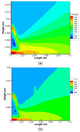
3.1 Fluid flow characteristics for offset ratio three and at different Re
Figures 3-5 illustrate the velocity contours, vectors, and streamlines (offset ratio = 3 and Reynolds number 5000 to 20,000) along the axial direction to study the fluid flow behavior. It is observed that the counter-rotating vortices are generated in between the wall and the offset jet at lower Reynolds numbers. However, the intensity of these vortices is weaker at higher Reynolds numbers. It happens due to a decrease in velocity of the offset jet along the axial distance. There is negative velocity obtained between the two jets due to which a reverse flow occurs. The flow becomes positive after the merge point. The axial distance of the merge point for lower Reynolds number flow is higher. It is due to the zero wall shear stress in this region. After the merge point, it behaves like a wall jet.
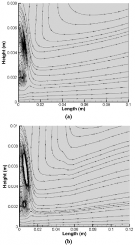
The streamline at different Reynolds number is plotted in Figure 5. It can be seen that two vortices are obtained for Reynolds number 5,000 and 10,000. At higher Reynolds number these vortices are merged. It is obvious that there is no change of streamlines from bottom to top in a vertical direction. This may be the reason for the higher intensity of the upper vortex as compared to a lower vortex.
Figure 3. Velocity contour for offset ratio 3 and Re (a) 5000 (b) 10,000 (c) 15,000 (d) 20,000
Figure 4. Velocity vector for offset ratio 3 and Re (a) 5000 (b) 10,000 (c) 15,000 (d) 20,000
Figure 5. Velocity streamlines for offset ratio 3 and Re (a) 5000 (b) 10,000 (c) 15,000 (d) 20,000
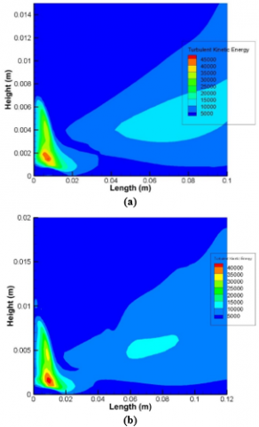
3.2 Turbulence kinetic energy (TKE) for offset ratio three at different Re
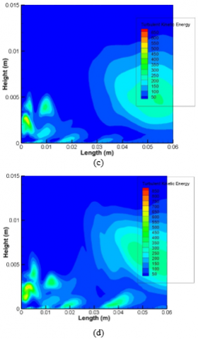
Figure 6 illustrates the turbulence kinetic energy (TKE) for an offset ratio of 3 at different Reynolds numbers. TKE is the energy content of the eddies formation in the turbulent flow. The size of the vortices defined the energy of such eddies.
It is noted that the TKE is quite low in the outer layer of the wall jet and the inner layer of the offset jet for each case. It may happen due to higher energy dissipation in these regions. However, it has a maximum value in the recirculation region. The intensity of TKE is higher for high Reynolds number flow. It is also observed that the maximum TKE occurs near the merge point. Figure 6 (c) and (d) show that the TKE is dispersed randomly along the horizontal and vertical direction due to the high Reynolds number of the fluid.
Figure 6. Turbulent kinetic energy for offset ratio 3 and Re (a) 5000 (b) 10,000 (c) 15,000 (d) 20,000
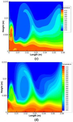
3.3 Temperature distribution for offset ratio three at different Re
Figure 7 represents the temperature variation along the axial length. The inlet jets are impinging and merge each other and heated by the constant heat flux provided at the bottom wall. Due to the heat flux, the temperature of the merged fluid becomes higher. It is clearly shown that at higher Re, the temperature distribution near the wall is highly influenced along the vertical direction as well as the axial direction. It happens because of an increase in the convective heat transfer coefficient of the fluid. For higher Reynolds numbers, the temperature drop region shifted towards the bottom wall.
Figure 7. Temperature distribution for offset ratio 3 and Re (a) 5000 (b) 10,000 (c) 15,000 (d) 20,000
3.4 Comparison of fluid flow and thermal properties for different offset ratio and constant Re
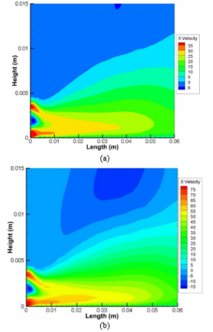
Figures 8 and 9 represent the variation of axial velocity contours and streamlines for the offset ratio of 7 and 9 at a constant Reynolds number (15,000). It is noticed that the axial velocity decreases with an increase in the offset ratio.
The magnitude of vortex formation near the wall jet and in between the wall and offset jet diminishes with the increase of offset ratio. It happens due to the flow becomes fully developed in the case of the higher offset ratio. It is also observed that the vortex center of the upper vortex increases at an offset ratio of 9.
Figure 8. Axial velocity at Re: 15,000 and offset ratio of (a) 7 (b) 9
Figure 9. Velocity streamlines at Re: 15,000 and offset ratio of (a) 7 (b) 9
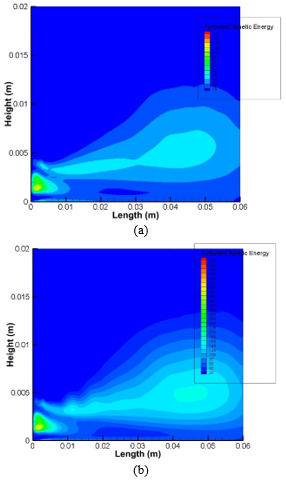
Figure 10 illustrates the contour of TKE at different offset ratio. The intensity of TKE is higher near the jet inlet at a lower offset ratio and decreases rapidly with a higher offset ratio due to a decrease in the axial velocity of the fluid. The TKE distribution along the vertical direction will be higher in case of a higher offset ratio.
Figure 10. Turbulent kinetic energy at Re: 15,000 and offset ratio of (a) 7 (b) 9
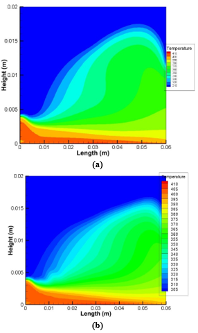
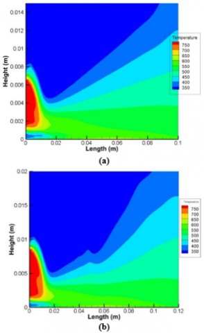
Temperature variation is one of the important aspects of this study. The temperature distribution varies at different offset ratio. Figure 11 illustrates that the temperature increases for the higher offset ratio because of lower axial velocity. it is observed that the temperature distribution near the inlet is higher which reduces along the axial direction.
Figure 11. Temperature contour at Re: 15,000 and offset ratio of (a) 7 (b) 9
Numerical analysis of a dual jet consisting of plane wall jet and a parallel offset jet is carried out using the standard k-ε RNG turbulence model. The effect of wall heat flux on fluid flow and its thermal characteristics are visualized at different offset ratios (3, 7, and 9) and Reynolds number (5000-20,000). The recirculation regions and two counter-rotating vortices are identified at different Reynolds numbers. It is noticed that the intensity of the upper vortex decreases by increasing the offset ratio. However, for offset ratio 3, the increases of Reynolds number decrease the flow circulation near the wall and offset jets but the axial distance of the merging point of jets is reduced. The temperature distribution is also highly affected by the offset ratio.
|
a |
Jet width (m) |
|
cP |
specific heat, J/kg. K |
|
D |
Offset |
|
g k |
gravitational acceleration, m/s2 thermal conductivity, W/m. K |
|
p |
Pressure (Pa) |
|
u |
Fluid velocity (m/s) |
|
Greek symbols |
|
|
ρ |
Density (kg/m3) |
|
µ |
dynamic viscosity, (Pa.s) |
|
Subscripts |
|
|
t |
Turbulence transport term |
[1] Glauert, M.B. (1956). The wall jet. Journal of Fluid Mechanics, 1(6): 625-643. https://doi.org/10.1017/S002211205600041X
[2] Kumar, A. (2015). Mean flow characteristics of a turbulent dual jet consisting of a plane wall jet and a parallel offset jet. Computers & Fluids, 114: 48-65. https://doi.org/10.1016/j.compfluid.2015.02.017
[3] Nasr, A., Lai, J.C.S. (1997). Comparison of flow characteristics in the near field of two parallel plane jets and an offset plane jet. Physics of Fluids, 9(10): 2919-2931. https://doi.org/10.1063/1.869404
[4] Rathore, S.K., Das, M.K. (2013). Comparison of two low-Reynolds number turbulence models for fluid flow study of wall bounded jets. International Journal of Heat and Mass Transfer, 61: 365-380. https://doi.org/10.1016/j.ijheatmasstransfer.2013.01.062
[5] Kumar, A., Das, M.K. (2011). Study of a turbulent dual jet consisting of a wall jet and an offset jet. Journal of Fluids Engineering, 133(10). https://doi.org/10.1115/1.4004823
[6] Vishnuvardhanarao, E., Das, M.K. (2009). Study of the heat transfer characteristics in turbulent combined wall and offset jet flows. International Journal of Thermal Sciences, 48(10): 1949-1959. https://doi.org/10.1016/j.ijthermalsci.2009.02.020
[7] Mondal, T., Guha, A., Das, M.K. (2015). Computational study of periodically unsteady interaction between a wall jet and an offset jet for various velocity ratios. Computers & Fluids, 123: 146-161. https://doi.org/10.1016/j.compfluid.2015.09.015
[8] Mondal, T., Das, M.K., Guha, A. (2014). Numerical investigation of steady and periodically unsteady flow for various separation distances between a wall jet and an offset jet. Journal of Fluids and Structures, 50: 528-546. https://doi.org/10.1016/j.jfluidstructs.2014.07.009
[9] Mondal, T., Guha, A., Das, M.K. (2016). Effect of bottom wall proximity on the unsteady flow structures of a combined turbulent wall jet and offset jet flow. European Journal of Mechanics-B/Fluids, 57: 101-114. https://doi.org/10.1016/j.euromechflu.2015.12.003
[10] Singh, T., Kumar, A., Satapathy, A.K. (2020). Heat Transfer and Fluid Flow Characteristics of a Turbulent Dual Jet Impinging on a Wavy Surface. Journal of Thermal Science and Engineering Applications, 12(4): 041017. https://doi.org/10.1115/1.4045882
[11] Pelfrey, J.R.R., Liburdy, J.A. (1986). Mean flow characteristics of a turbulent offset jet. Journal of Fluids Engineering, 108(1): 82-88. https://doi.org/10.1115/1.3242548
[12] Patankar, S. (2018). Numerical Heat Transfers and Fluid Flow. Taylor & Francis.
[13] Kumar, M., Sahoo, R.K., Behera, S.K. (2019). Design and numerical investigation to visualize the fluid flow and thermal characteristics of non-axisymmetric convergent nozzle. Engineering Science and Technology, an International Journal, 22(1): 294-312. https://doi.org/10.1016/j.jestch.2018.10.006