Younes Menni* | Ali J. Chamkha | Giulio Lorenzini | Houari Ameur | Mohamed Salmi | Djamal Fridja
© 2020 IIETA. This article is published by IIETA and is licensed under the CC BY 4.0 license (http://creativecommons.org/licenses/by/4.0/).
OPEN ACCESS
This manuscript reports numerical data of computational analyses of oil flows in two-dimensional horizontal rectangular cross section pipes with upper and lower wall-placed staggered solid flat baffles and fins. The physical properties of fluid (oil) and solid (Al) are constant. The flow is assumed to be steady, turbulent, and incompressible. The velocity profile at the entrance is uniform one-dimensional. The fluid temperature is set equal to 298 K at the inlet section. The upper pipe surface was put in a constant temperature condition, as the lower surface was thermally insulated. The atmospheric pressure is prescribed at the pipe outlet. Impermeable boundary and no-slip wall conditions are applied for the pipe walls and the baffle plates. The radiation mode of heat transfer is neglected according to other modes of heat transfer. Two various baffled pipe configurations are treated. The technique CFD is applied in the calculation. The Reynolds number is varied from 12,000 to 32,000, and different fields, i.e., dynamic pressure, velocity-magnitude, turbulent kinetic energy, and turbulent viscosity, are presented and analyzed numerically.
dynamic pressure, turbulent kinetic energy, turbulent viscosity, oil flow, baffled pipe
The inclusion of baffles and fins inside the thermal solar receiver channels is among the most effective mechanisms for important thermal exchange by creating turbulence, extending the trajectory of the flow, increasing the surface of heat exchange, forcing recycling cells, and hence a high thermal exchange. Many researchers have numerically and/or experimentally treated this subject. Baissi et al. [1] investigated the heat transfer and energy loss due to flow friction in the absorber surface of a SAH channel fitted with perforated and non-perforated longitudinally curved delta-shaped baffles. Significant heat transfer rates, as well as a significant increase in friction factor have been obtained when compared to those obtained with smooth channel. Fawaz et al. [2] carried out a numerical simulation to examine a periodic fully developed turbulent flow and thermal characteristics for air flow in a square channel fitted with 45 V-baffles. Higher blockage ratios and/or lower baffles pitch ratios resulted in an increase in Nusselt number. Ghiami and Ghiami [3] experimentally evaluated a novel baffle-equipped SAH with integrated storage unit (PCM cavity) in terms of its performance, under the meteorological conditions of Mashhad, Iran. This study aimed at two main objectives. Firstly, the system is investigated, at different flow rates and different baffles location, to understand the effectiveness of exploitation of baffles in a solar air heater, while the SAH is being utilized by a slab of PCM material. Hu et al. [4] conducted a study to improve the thermal performance of baffle-type solar air collector (BSAC) by opening holes on baffle based on the principle of windbreak walls. The results revealed the mechanism of heat transfer enhancement and provided the theoretical basis for the optimization of BSACs. Hu et al. [5] also proposed a novel idea to optimize thermal performance of baffle-type solar air collector by narrowing the first chamber through rearranging the baffles in the collector. The collector with five chambers divided by four baffles was investigated numerically and experimentally, and the mechanism of performance improvement was revealed by flow and heat transfer analysis. Kumar et al. [6] examined the augmentation in heat transfer and friction in a flow through solar air channel with discretized broken V-pattern baffle. Kumar et al. [7] also carried out an experimental investigation on the performance of solar air channel, having the heated plate with rough in the form of multi V-baffle. The results revealed that the broken multiple V-type baffles are thermo-hydraulically superior as compared to the other baffles shaped solar air channel. Kumar et al. [8] also presented an experimental study on heat transfer and friction characteristics of solar air channel fitted with discretized broken V-pattern baffle on the heated plate. The effect of geometrical parameters, predominantly the gap width and gap location were investigated. Li et al. [9] carried out a three-dimensional numerical analysis to investigate the turbulent flow and heat transfer characteristics in the channel with multi V-shaped baffles. The numerical optimization indicated that the enhancement of the thermal performance factor can achieve 12% in this channel with multi V-shaped baffles. Menasria et al. [10] numerically investigated the turbulent flow and convective heat transfer of air inside channel of rectangular cross-section, containing rectangular baffles with inclined upper part planted on the opposite surface of absorber plate under solar air heater boundary conditions. Sahel et al. [11] carried out a numerical study to investigate the turbulent flows and heat transfer characteristics in a rectangular channel fitted with two baffles placed on the upper and lower walls. These baffles were perforated by a row of four holes at three different positions. Sahel and Benzeguir [12] presented a numerical investigation of heat transfer and friction factor characteristics in a solar air heater channel fitted with upper corrugated surface/wall and baffle series placed on a lower wall along the length of the channel. Saravanakumar et al. [13] carried out analytical modeling to study the effect of absorber plate integrated with arc shaped rib roughened barrier with fins and baffles on thermal and effective efficiency of a solar air heater.
Tamna et al. [14] presented a study on heat transfer augmentation in a solar air heater channel fitted with multiple V-baffle vortex generators. Wei et al. [15] presents an original study on the design and optimization of baffled fluid distributor for the realization of optimal fluid flow distribution in a tubular solar receiver.
This study reports CFD based simulations of dynamic pressure and kinetic energy fields in two-dimensional horizontal rectangular cross section pipes provided by top and bottom wall-attached obstacles using oil as the heat transfer fluid at Reynolds numbers varying from 5,000 to 25,000.
The current model under consideration is a 2D horizontal rectangular pipe fitted with three obstacles arranged on both top and bottom surfaces with a staggered manner as reported in Figure 1. These obstacles are inserted in the pipe to force recycling cells, to improve mixing, and consequently the heat transfer. The impact of obstacle arrangement manner and Reynolds number on the dynamic pressure and kinetic energy fields of oil flow are investigated in detail. Two various baffled pipe models (A and B) are considered, as shown in Figure 1 a and b. All engineering dimensions as well as all necessary boundary conditions are also shown in Figure 1.
Figure 1. Physical model under consideration: (a) case A, and (b) case B
These models are studied according to the following assumptions and boundary conditions:
- The flow is assumed to be steady, turbulent, and incompressible.
- The thermophysical properties of the fluid (oil) and solid (Al) are constant. The thermophysical properties (density ρf, specific heat at constant pressure Cpf, dynamic viscosity μf, and thermal conductivity kf) of the fluid (oil) are presented in Reference [16].
- The velocity profile at the pipe entrance is uniform one-dimensional, u = Uin.
- The temperature (Tin) of the oil fluid is set equal to 298 K at the inlet of the pipe [16]
- The upper pipe surface was put in a constant temperature condition (Tw = 375 K), as the lower surface was insulated.
- The atmospheric pressure (Patm) is prescribed at the channel outlet [17].
- Impermeable boundary and no-slip wall conditions are applied for the channel and obstacle walls.
- The radiation heat transfer mode is neglected according to other modes of heat transfer.
The conservation equations of mass, momentum and energy, employed to describe the steady turbulent incompressible flow in the computational domain under consideration, are presented in Reference [18].
Finite Volume method (FV) [19], Semi Implicit Method for Pressure Linked Equations algorithm (SIMPLE) [19], Quadratic Upstream Interpolation for Convective Kinetics numerical scheme (Quick) [20], and Standard k-epsilon turbulence model (k-ε), by means of Commercial CFD software FLUENT are used in simulation.
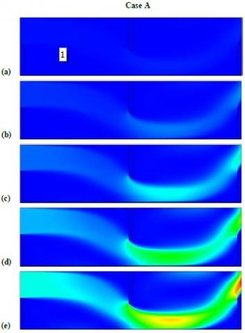
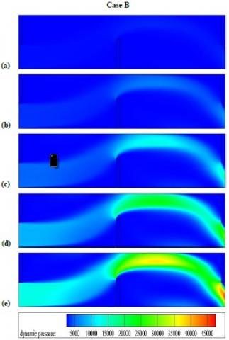
Figure 2. Dynamic pressure (P) fields for various studied cases and (a) Re = 5,000, (b) Re = 10,000, (c) Re = 15,000, (d) Re = 20,000, and (e) Re = 25,000. P values in Pa
4.1 Dynamic pressure field (P)
As shown in Figure 2 a-e, the oil current flows from the upper input of the pipe in the first case (Case A), while from the lower entrance in the second case (Case B).
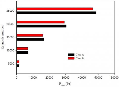
The dynamic pressure values are considered from the inlet of the pipe to its output. This increase in pressure values augments on the top front edges of the second and the third obstacles and in both A and B cases, especially for large values of Reynolds, as reported in Figures 2 a-e and 3.
The dynamic pressure values are very low on the front and back areas of the obstacles, near the upper and lower walls of the pipe in both studied cases.
As shown in Figures 2 a-e and 3, the first case shows higher pressure values, especially in the case of Re number of 25,000.
Figure 3. Pmax values for various Reynolds numbers and different investigated cases
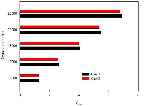
4.2 Velocity-magnitude field (V)
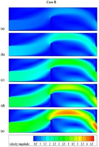
As shown in Figure 4 a-e, mean velocity values are very high near the walls of the pipe, between the last two obstacles, as well as near their upper frontal sides. This rise in velocity is the result of a change in flow direction due to the presence of obstacles.
The velocity values are also increased between the sharp edges of the obstacles and the pipe walls due to the higher pressure values due to the decrease in flow area.
As expected, the velocity values are very low on the left and right faces of the obstacles due to the low pressure in these regions.
Also there is a direct correlation between the velocity values and the Reynolds number values in both A and B cases, Figures 4 a-e and 5.
Furthermore, the presence of obstacles inside the first pipe (Case A) contributes to the formation of strong cells for recycling with high flow speeds (see Figures 4 a-e and 5) compared to the B second case.
This improvement in flow dynamics increases with increasing Re values.
Figure 4. Velocity-magnitude (V) field for various studied cases and (a) Re = 5,000, (b) Re = 10,000, (c) Re = 15,000, (d) Re = 20,000, and (e) Re = 25,000. V values in m/s
Figure 5. Vmax values for various Re numbers and different examined cases
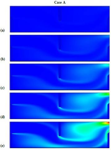
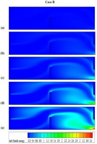
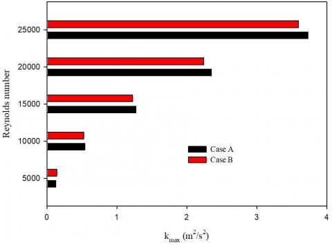
4.3 Turbulent kinetic energy field (K)
It is very clear that the values of turbulent kinetic energy (K) are very low for small values of Reynolds number (see Figure 6 a-e). These values are improved by improving Reynolds number values (see Figures 6 and 7). This improvement is shown on the back regions of the first and second obstacles (see Figure 6). This enhancement is due to the presence of recycling cells on their right sides and in both cases analyzed.
The values of K energy are super in the first pipe case with one fin and two baffles, while they are low in the second case (see Figures 6 a-e and 7).
Figure 6. Turbulent kinetic energy (K) fields for various studied cases and (a) Re = 5,000, (b) Re = 10,000, (c) Re = 15,000, (d) Re = 20,000, and (e) Re = 25,000. K values in m2/s2
Figure 7. Kmax values for various Re numbers and different examined cases
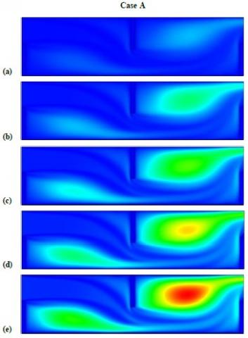
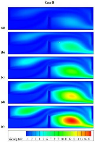
4.4 Turbulent viscosity field (μ)
The turbulent viscosity values are very weak on the left sides of the last two obstacles in both cases, while their values rise on the back regions of the first and second obstacles (see Figure 8 a-e).
Figure 8. Turbulent viscosity (μ) fields for various studied cases and (a) Re = 5,000, (b) Re = 10,000, (c) Re = 15,000, (d) Re = 20,000, and (e) Re = 25,000. μ values in Kg/m-s
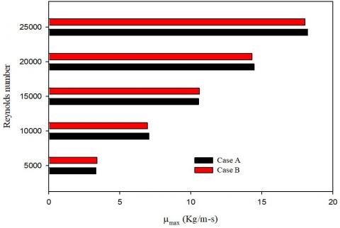
Figure 9. μmax values for various Re numbers and different examined cases
Their maximal values are present in the region confined between the last two obstacles, and are positioned in the center of the large vortex located in this region. These values increase as the number of Reynolds increases (see Figures 8 a-e and 9). The first considered case (Case A) records the highest viscosity values especially for a high value of Reynolds number (see Figures 8 a-e and 9).
The most important conclusions that can be drawn from this study are as follows:
[1] Baissi, M.T., Brima, A., Aoues, K., Khanniche, R., Moummi, N. (2019). Thermal behavior in a solar air heater channel roughened with delta-shaped vortex generators. Applied Thermal Engineering, 165: 113563. https://doi.org/10.1016/j.applthermaleng.2019.03.134
[2] Fawaz, H.E., Badawy, M.T.S., Abd Rabbo, M.F., Elfeky, A. (2017). Numerical investigation of fully developed periodic turbulent flow in a square channel fitted with 45° in-line V-baffle turbulators pointing upstream. Alexandria Engineering Journal, 57(2): 633-642. http://dx.doi.org/10.1016/j.aej.2017.02.020
[3] Ghiami, S., Ghiami, A. (2017). Comparative study based on energy and exergy analyses of a baffled solar air heater with latent storage collector. Applied Thermal Engineering, 133: 797-808. https://doi.org/10.1016/j.applthermaleng.2017.11.111
[4] Hu, J., Liu, K., Ma, L., Sun, X. (2018). Parameter optimization of solar air collectors with holes on baffle and analysis of flow and heat transfer characteristics. Solar Energy, 174: 878-887. https://doi.org/10.1016/j.solener.2018.09.075
[5] Hu, J., Liu, K., Guo, M., Zhang, G., Chu, Z., Wang, M. (2019). Performance improvement of baffle-type solar air collector based on first chamber narrowing. Renewable Energy, 135: 701-710. https://doi.org/10.1016/j.renene.2018.12.049
[6] Kumar, R., Chauhan, Ra., Sethi, M., Kumar, A. (2016). Experimental study and correlation development for Nusselt number and friction factor for discretized broken V-pattern baffle solar air channel. Experimental Thermal and Fluid Science, 81: 56-75. http://dx.doi.org/10.1016/j.expthermflusci.2016.10.002
[7] Kumar, R., Kumar, A., Chauhan, R., Sethi, M. (2016). Heat transfer enhancement in solar air channel with broken multiple V-type baffle. Case Studies in Thermal Engineering, 8: 187-197. http://dx.doi.org/10.1016/j.csite.2016.07.001
[8] Kumar, R., Sethi, M., Chauhan, R., Kumar, A. (2017). Experimental study of enhancement of heat transfer and pressure drop in a solar air channel with discretized broken V-pattern baffle. Renewable Energy, 101: 856-872. http://dx.doi.org/10.1016/j.renene.2016.09.033
[9] Li, J.L., Tang, H.W., Yang, Y.T. (2018). Numerical simulation and thermal performance optimization of turbulent flow in a channel with multi V-shaped baffles. International Communications in Heat and Mass Transfer, 92: 39-50. https://doi.org/10.1016/j.icheatmasstransfer.2018.02.004
[10] Menasria, F., Zedairia, M., Moummi, A. (2017). Numerical study of thermohydraulic performance of solar air heater duct equipped with novel continuous rectangular baffles with high aspect ratio. Energy, 133: 593-608. https://doi.org/10.1016/j.energy.2017.05.002
[11] Sahel, D., Ameur, H., Benzeguir, R., Kamla, Y. (2016). Enhancement of heat transfer in a rectangular channel with perforated baffles. Applied Thermal Engineering, 101: 156-164. http://dx.doi.org/doi:10.1016/j.applthermaleng.2016.02.136
[12] Sahel, D., Benzeguir, R. (2017). Thermal characteristic in solar air heater fitted with plate baffles and heating corrugated surface. Energy Procedia, 139: 307-314. http://dx.doi.org/doi:10.1016/j.egypro.2017.11.213
[13] Saravanakumar, P.T., Somasundaram, D., Matheswaran, M.M. (2019). Thermal and thermo-hydraulic analysis of arc shaped rib roughened solar air heater integrated with fins and baffles. Solar Energy, 180: 360-371. https://doi.org/10.1016/j.solener.2019.01.036
[14] Tamna, S., Skullong, S., Thianpong, C., Promvonge, P. (2014). Heat transfer behaviors in a solar air heater channel with multiple V-baffle vortex generators. Solar Energy, 110: 720-735. http://dx.doi.org/10.1016/j.solener.2014.10.020
[15] Wei, M., Fan, Y., Luo, L., Flamant, G. (2016). Design and optimization of baffled fluid distributor for realizing target flow distribution in a tubular solar receiver. Energy, 136: 126-134. http://dx.doi.org/10.1016/j.energy.2016.04.016
[16] Gholami, M.R., Akbari, O.A., Marzban, A., Toghraie, D., Shabani, G.A.S., Zarringhalam, M. (2017). The effect of rib shape on the behavior of laminar flow of oil/MWCNT nanofluid in a rectangular microchannel. Journal of Thermal Analysis and Calorimetry, 134(3): 1611-1628. http://dx.doi.org/10.1007/s10973-017-6902-3
[17] Demartini, L.C., Vielmo, H.A., Möller, S.V. (2004). Numeric and experimental analysis of the turbulent flow through a channel with baffle plates. J. Braz. Soc. Mech. Sci. Eng., 26(2): 153-159. https://doi.org/10.1590/S1678-58782004000200006
[18] Menni, Y, Azzi, A, Chamkha, AJ, Harmand, S. (2018). Effect of wall-mounted V-baffle position in a turbulent flow through a channel: Analysis of best configuration for optimal heat transfer. International Journal of Numerical Methods for Heat & Fluid Flow, 29(10): 3908-3937. https://doi.org/10.1108/HFF-06-2018-0270
[19] Patankar, S.V. (1980). Numerical Heat Transfer and Fluid Flow. McGraw-Hill, New York.
[20] Leonard, B.P., Mokhtari, S. (1990). Ultra-Sharp nonoscillatory convection schemes for high-speed steady multidimensional flow. NASA TM 1-2568, NASA Lewis Research Center.