OPEN ACCESS
The body of Economy Power Racing Car (EPRC) required by Energy Saving Sports Contest not only complies with the compactness requirement of operation space for the driver also with higher requirement of its aerodynamics and light weight. Therefore, the software of XFLOW was selected to achieve the optimal solution. On this basis, we did the numerical simulation of the external flow field for the solution which has been selected by using the software of FLUENT. According to the situation, the material of carbon fiber composite was applied in the body of EPRC which satisfies the requirements of Energy Saving Sports Contest.
Economy power racing car, Aerodynamics, Light weight, Carbon fiber composite
In the past decade, the oil crisis facing by the world today is reached to a critical level. Therefore, in the past few years there has been a growing concern about fuel consumption all over the world [1-3]. Energy Saving Sports Contest which not only attracts hundreds of domestic and foreign team actively participate in, but also to promote more new techniques applied to the model of the car. The smaller the resistance of the car, the smaller the fuel consumption, and the results of the competition can also be improved. The decrease of energy-saving car rolling resistance can be achieved by reducing the total weight of car or using the tire rolling with smaller resistance coefficient. But the size of the air resistance is largely depending on the EPRC aerodynamic performance. So in order to achieve better results, the methods of designing and manufacturing energy saving car body is the key to meet the requirements.
In view of the situation above, many domestic competitors participant in this study: Guo Yan and his colleagues established the CAD model of vehicle body and use the XFLOW fluid analysis software to achieve the body fluid analysis. Qi Yiqiang [4] and his colleagues used the fluent software to precede a numerical simulation on the body of the EPRC by comparing the drag coefficient, lift coefficient and other parameters in order to determine the final body
shape. Zhang Jianchang [5] and his colleagues established the entire package and half shaped body and then used the ANSYS software to simulate the drag coefficient of wind tunnel and introduced the advantages of carbon fiber to produce the carbon fiber body. But the literatures above had only preceded a single CFD analysis and the software of FLUENT need to spend a lot of time on the mesh. It consumed a lot of time and efforts to compare several projects and difficult to achieve a comparison detailed on a variety of programs and form a standard procedure for a set of relatively complete body design system. This paper combines the advantages of XFLOW and FLUENT on the body analyze. Firstly using the characteristics of mesh of XFLOW to select the optimal scheme quickly, and then using the FLUENT software to test and modify the preliminary plan according to the results of the flow field analysis. At the same time, the strict process requirements of the composite body must be guaranteed, the final body products meet the satisfaction of eliminating the drag maximize and the requirement of match.
The vehicle body space should have the following requirements:
Table 1. Basic space requirements of EPRC
|
Space requirement |
Quantitative / qualitative |
Range |
|
The front axle and wheel body inside |
Quantitative |
>=25mm |
|
Driver head and body top |
Quantitative |
>=30mm |
|
Driver’s view area |
Qualitative |
Enough |
|
Maximum rotation angle of the wheel and inner side of the vehicle body |
Quantitative |
>=10mm |
|
Body floor clearance |
Quantitative |
>=35mm |
The distance between wheels on the front axle and the inside vehicle body refers to the minimum distance between wheels on the front axle and inside vehicle body while racing in straight driving. This will ensure that the axle of front wheel cannot interference the body in any driving state. The distance between the driver’s head and the top of the body is the minimum distance between the top of the helmet and the vehicle body when drivers sit in standard position wearing helmet. This distance will ensure the safety of the head while the ups and downs in the racing road. The suffice of driver’s vision means that the width of the front view must be at least 90 degrees when driving in the normal posture and that the driver can see the objects measuring 80cm directly without the use of auxiliary equipment. The distance between the wheel angle and the vehicle inner side means that the steering angle of the front wheel car can ensure the minimum turning radius of 20m, and the minimum distance that do not interfere with the body. The distance between the body floor clearance and the ground refers to the minimum distance which will ensure that the car on the track when the road not be interfered by any road conditions.
To ensure the 5 points above, the PART module in CATIA software was used to establish the EPRC frame, wheels and other parts. The PRODUCT module in CATIA software was used to assemble all the parts and the application of human builder module of CATIA software in order to provide a fake driver with the same height of real drivers intending to simulate the real driving posture. And the body should meet the requirements of the external dimensions of the competition. The height of the car has to be equal to or less than 1.8 meters, total length of the car has to be equal to or less than 3.5 meters and the full width S have to be equal or less than 2.5 meters.
Figure 1. The space requirement of the EPRC
2.2 Aerodynamic requirements for EPRC
2.2.1 Establishment of CAD Model of EPRC
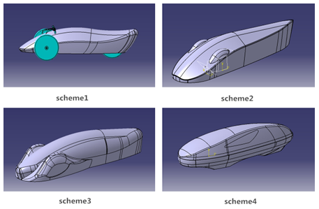
The car shell shape uses streamlined design, which can reach the goals of reducing the investment area, guiding the airflow and reducing air resistance [6]. But taking into account that the different design options, for instance whether the body is all inclusive or whether the wheels are raised, will cause different effects on the vehicle performance. So firstly we used the software CATIA to generative shape design module designed to meet the different schemes of energy-saving and vehicle space requirements [7]. At the same time, the scheme needs to meet the requirement of compact space of the driver and ensure the basic space requirements while minimizing unnecessary waste of space.
Figure 2. Four bodies design
In scheme 1, the wheels are exposed, which can greatly reduce the quality of the body. But the occupant in the internal space is narrow and the vision is relatively narrow too. In scheme 2, all the wheels are inclusive and convex, which can reduce the body mass while developing the appearance of beauty. But the assembly of the wheels needs high precision and the angle will decrease. In scheme 3, all the wheels are inclusive and bulging outward, which can ensure the bigger interior space and enough steering angle. But the manufacture is difficult. In scheme 4, all the wheels are inclusive and overall appearance is smooth, which ensure an adequate view and is easy to fabricate, but quality of the body is mass.
2.2.2 Analysis of the External Flow Field of EPRC
In order to obtain the objective truth theory data to determine what kind of body shape dynamics performance is the best, the computational fluid dynamics CFD (Computational Fluid Dynamics) software was used to analyze the body and determine the dynamic performance of the best body by comparison of the data.
Using XFLOW software to do the body of the CFD analysis is because the traditional CFD software such as Fluent requires using the pre-processing software for grid division, and need to verify the model parameters. And the numerical stability requirements are higher. The discrete method of XFLOW software is based on particle Boltzmann method adaptive to dynamic refinement, according to the demand of automatic mesh generation, used a patented particle and complete Lagrangian function simply deal with the traditional complex computational fluid dynamics (CFD) problem [8].
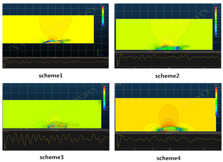
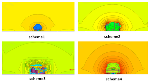
Setting the size of the simulation wind tunnel which is 4*4*12m, atmospheric conditions are defined as the standard atmospheric conditions. The speed is set to match the average speed of 36km/h or 10m/s. The fluid material is air, and its properties are: density 1.225kg, temperature 288.15K. And set the position of the CAD model of the car body. After setting the parameters which can be calculated respectively, which showed in Figure 3and 4.
Figure 3. A certain time step velocity slice Image
Figure 4. Contour map of a time step
It can be seen from the velocity slice image and contour map:
Taking into the XFLOW fluid analysis tool of the grid is automatically divided, the degree of fertilization is limited and the analysis of the details of the performance is not good enough too, at the same time, fluent software includes a pressure of the segregated solver, based on pressure coupled solver, based on the density of the implicit solver, explicit solver based on density, multiple solver technology enable FLUENT software can be used to simulate incompressible up to higher supersonic range for a variety of complex flow field, which accuracy is greatly improved up to second order accuracy. So the FLUENT software has been used to determine the solution of fluid analysis, further validation of the feasibility of the program [9].
3.1 The external flow field numerical simulation for EPRC
3.1.1 Determine the size of the calculation domain
Because the body model is the face of the center said, the reason for the calculation of the time is only half of the body division grid. The semi model has a larger grid density, so the number of nodes in the unit volume is much more, which can better reflect the flow field around the body.
Through the numerical simulation of the experience, the whole region is cuboids. The entrance length is 3 times as the length, entrance length is 7 times as the length, width is 4 times as the width of the vehicle, and vehicle height is taken 5 times higher. The computational domain is a long length, width and height, which are 26000, 3040 and 3000mm respectively, shown in figure 5.
Figure 5. Schematic diagram of the calculation domain
3.1.2 Mesh Division
In order to ensure the accuracy of the latter, the following principles are considered in the grid division:
In order to obtain the high quality of the grid, using HyperMesh to deal with the wind tunnel meshing module, and setting up a simple wind tunnel the coordinate values can get high quality grid, then modify the part of the grid which be imported into fluent.
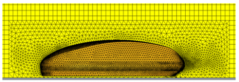
Figure 6. Computational domain global grid
Figure 7. The maximum cross section of the body of the grid
Figure 8. Vehicle body vertical planar grid
The total number of final model is 212076, the total number of nodes is 94407. It includes 7 surface meshes and 1 individual grid, 7 surface meshes are body, entrance, exit, two sides, top and ground, respectively.
3.1.3 Determination of physical model
The body of EPRC is at the time of travel and the surrounding fluid is viscous air gas. Simulating the real environment of the game temperature is 25 degrees Celsius, air density $\rho=1.185 \mathrm{kg} / \mathrm{m}^{3}$ , dynamic viscosity coefficient $\mu=1.81 \times 10^{-5} N \cdot s / m^{2}$, kinematic viscosity $v=1.5274 \times 10^{-5} \mathrm{m}^{2} / \mathrm{s}$. When the vehicle speed is up to 250km/h, the flow field of the Maher number is about 0.19. But when the Maher number is less than 0.3, the compressibility of the air flow can be neglected. Due to the maximum speed is 60km/h, so the flow field for the EPRC is directly perceived through the senses, according to the steady, isothermal, incompressible three-dimensional flow field for processing [10].
Simulation of the real situation, the flow speed v=10m/s, that is 36km/h. The Reynolds number obtained from the calculation domain inlet size is:
$\mathrm{Re}=\mathrm{v} 1 / v=(10 \times 3) /\left(1.5274 \times 10^{-5}\right)=1.96 \times 10^{6}$ (1)
The flow belongs to the high Reynolds number turbulence, and it is necessary to choose a kind of turbulence model to simulate the flow. According to the computing power of the computer and the requirement of the quality of the grid, this paper selected the higher Reynolds number $\kappa-\varepsilon$ turbulence model.
3.1.4 Boundary conditions setting
The numerical simulation of the external flow field is carried out in the finite element model, so it is necessary to define the boundary conditions on the six surfaces of the computational domain. The boundary condition demands to satisfy the adaptability in mathematics, and has obvious meaning in physics. In this paper, the boundary condition of the energy saving vehicle is set to 5 kinds: the inlet boundary, the exit boundary, the moving ground boundary, the fixed boundary condition and the boundary condition, which were shown in table 2.
Table 2. Calculation of boundary conditions
|
region |
boundary condition |
|
Entrance |
Velocity inlet boundary, velocity of v=10m/s, direction perpendicular to the entrance wall |
|
Exit |
Pressure outlet boundary condition, static pressure is zero. |
|
Ground |
Moving wall condition, wall movement speed v=30m/s |
|
Side |
Static wall boundary condition |
|
Vehicle surface |
Static wall boundary condition |
|
Top and face |
Symmetric boundary condition |
3.2 Numerical simulation results analysis
3.2.1 Body center surface velocity vector distribution
Figure 9. Velocity vector distribution of body center
From above figure 9, which shows that the front of the body is blocked, the pressure is large. For the positive pressure area, the speed is small. From the front of the air flow divided into two streams, the upper airflow by the front of the attraction of the role of air flow distribution, in front of the glass top air flow again close to the car surface. The rear area is more complex, in the rear of the car to form a flow separation, and there is a speed lag area. The speed at the back of the car gets smaller, and then the speed at which it is far away from the car is close to the speed of the car.
3.2.2 Body surface velocity vector distribution
Figure 10. Velocity vector distribution of body surface
According to the partial pressure and velocity vector in figure 10, we can see that the place where the pressure is high but small, and when the pressure is low which shows that the calculation result is in line with the basic law of fluid flow. Due to the energy vehicle body surface velocity vector can be seen, the front speed is small, the speed of behind the rear is large, which is consistent with the laws of fluid mechanics.
Flow pattern analysis of body surface
Figure 11. Flow line of the body surface
Figure 11 shows that in the tail of the vehicle tail flow, there are also parts of the whirlpool. The existence of vortex makes the flow field of the car is very complex, and there is a section of the air stagnation zone, which formed part of the vacuum area. Vacuum area is bigger, more resistance, so the movement of EPRC has great influence. But the body vortex is less, so the vacuum zone of resistance within the acceptable range.
In distance energy-saving tail of the car from a certain distance from the location, flow the backflow phenomenon, from the beginning of this position, with the increase of the distance, speed loss is more and more small, in far from the car, tail wind speed and air inlet velocity close. Analysis of the flow chart, especially the air flow line and through the analysis of the force on the surface of the car, the design of the flow pattern is very instructive [11].
3.2.4 Body of the longitudinal symmetry and body surface pressure distribution
When the front of the body is not ideal, the front will form a large positive pressure area, and there will be a lot of air separation area in the upper part of the car. In the rear of the car top and rear appeared high pressure zone, flow separation, and in the back of the car to form the wake, wake is automotive design patterns to be considered one of the factors, because the EPRC is at high speed, resulting in resistance of automotive main factors. However, due to the average vehicle speed in the 10m/s, the impact of the end can be ignored.
Figure 12. The distribution of pressure in the body of the vehicle body
Figure 13. Front and rear pressure distribution diagram
From Figure 12 and 13 show that in the upper and the bottom of the car formed a pressure difference, it is the existence of the pressure, so the car is an upward force, and this force is that we usually call as the lift.
Based on the above results, the numerical simulation results are analyzed and the feasibility of the implementation of the scheme is verified by the analysis results.
4.1 Body composite material selection
Because carbon fiber is a kind of advanced composite materials with light weight, high modulus, resistance to chemical corrosion, thermal expansion coefficient, a series of excellent properties, light (density of 1.6 - 2.5G) and high modulus (modulus is more than 5 times that of the metal), which are needed for saving Athletics competition, so carbon fiber is for energy-saving car body materials.
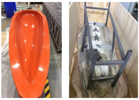
4.2 Body mold production and body molding
In order to ensure the consistency of size of the CAD model after the completion of the production; the outside shell surface should smooth. Sufficient strength and resistance to high temperature performance should be ensured for carbon fiber. Therefore, the production of materials for the glass fiber reinforced plastic mold and the surface of the mold after the application of gypsum should prevent the occurrence of adhesion. As shown in figure 14 and 15.
Figure 14. Body mold
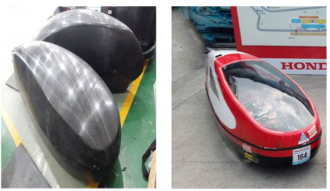
Figure 15. The production of finished carbon fiber body
The body uses a double layer carbon fiber cloth structure, the inner layer uses the 3K carbon fiber cloth, and the outer layer uses the 12K carbon fiber cloth. Remanufacturing process should ensure that the outer carbon fiber does not wrinkle, burr.
The adhesive should use two-component, slow-dry type epoxy resin, in which the first layer of carbon fiber cloth and second layers of carbon fiber cloth were laid. Attention should be paid to environmental temperature and humidity during the drying process. I should ensure that the temperature is greater than 20oC, the relative humidity is less than 85% while preventing the dust adhering to the dry surface caused by surface pollution.
After the model, the body should avoid direct sunlight, to avoid that the inner side of the epoxy resin is not completely dry deformation, resulting in the distortion and cracking of the body and other issues. The surface of the body should be careful and not to scratch the surface of carbon fiber reinforced layer resulting in the decline of the body structure stiffness.
Concentrating on the requirements and needs for energy-saving sports car race, using the theory of ergonomics and putting forward the requirements of the basic standard of sports car body design. Based on CATIA modeling tool designs and XFLOW-CFD analysis tool on several schemes which have different drag coefficient, perturbation flow, mean value of lift coefficient and other parameters, the subsequent aerodynamic test and plan were analyzed and compared, then determining the best one. Thereafter, using HyperMesh to mesh with wind tunnel mesh module l, using high precision CFD analysis software FLUENT to verify the feasibility of the scheme. On this basis, the body of EPRC can be produced with the selection of light, high modulus, corrosion resistance of carbon fiber composite material. The design process is proved feasible, and the desired objectives can be achieved.
This work is supported by Shanghai University of Engineering Science High Level Project to Cultivate Special (Project No. 201510856025).
[1] Akorede M. F., Hizam H. and Pouresmaeil E., “Distributed energy resources and benefits to the environment,” J. Renewable and Sustainable Energy Reviews, vol. 14, no.2, pp. 724–734, 2010.
[2] Omer A. M., “Energy, environment and sustainable development,” J. Renewable and Sustainable Energy Reviews, vol. 12, no.9, pp. 265-300, 2008.
[3] Uddin S. N., Taplin R. and Yu X., “Energy, environment and development in Bhutan,” J. Renewable and Sustainable Energy Reviews, vol. 11, no. 9, pp. 83-103, 2007.
[4] Qi Yiqiang and Tian Fang, “CFD study on the body shape of the energy saving competitive car,” J. Forest Engineering, vol. 5, no. 2, pp. 265-300, 2012.
[5] Zhang Jianchang, Zheng Duan, Cao Zhaoliang and Zhu Lixiang, “Energy saving vehicle body design,” J. Technology Vision, vol. 17, no. 3, pp. 158-159, 2014.
[6] Kaya K. and Ozcan O., “A numerical investigation on aerodynamic characteristics of an air-cushion vehicle,” Journal of Wind Engineering and Industrial Aerodynamics, vol. 120, no. 23, pp. 70-80, 2013.
[7] Ning H., Pillay S. and Vaidya U. K., “Design and development of thermoplastic composite roof door for mass transit bus,” J. Mater Des, vol. 30, no. 9, pp. 83–91, 2009.
[8] Janowski G. M., Vaidya U. K. and Husman G. “Thermoplastic sandwich structure design and manufacturing for the body panel of mass transit vehicle,” J. Compos Struck, vol. 80, no. 2, pp. 82–91, 2007.
[9] Miralbes R. and Castejon L., “Aerodynamic analysis of some boat tails for heavy vehicles,” International Journal of Heavy Vehicle Systems, vol. 19, no. 2, pp. 115-127, 2012.
[10] Taha Zahari, Passarella Rossi and Sugiyono. “CFD analysis for Merdeka 2 Solar Vehicle,” J. Advanced Science Letters, vol. 4, no.2, pp. 2807-2811, 2011.